Tektronix AFG3000 Series Reference Manual
Arbitrary/function generators
Hide thumbs
Also See for AFG3000 Series:
- Programmer's manual (232 pages) ,
- Service manual (164 pages) ,
- Quick start user manual (108 pages)

Subscribe to Our Youtube Channel
Related Manuals for Tektronix AFG3000 Series


Summary of Contents for Tektronix AFG3000 Series
- Page 1 Reference Manual AFG3000 Series Arbitrary/Function Generators 071-1639-00 This document supports firmware version 1.0.0 and above. www.tektronix.com...
- Page 2 Copyright © Tektronix, Inc. All rights reserved. Tektronix products are covered by U.S. and foreign patents, issued and pending. Information in this publication supercedes that in all previously published material. Specifications and price change privileges reserved. Tektronix, Inc., P.O. Box 500, Beaverton, OR 97077...
- Page 3 Tektronix, shipping charges prepaid, and with a copy of customer proof of purchase. Tektronix shall pay for the return of the product to Customer if the shipment is to a location within the country in which the Tektronix service center is located. Customer shall be responsible for paying all shipping charges, duties, taxes, and any other charges for products returned to any other locations.
-
Page 5: Table Of Contents
Contacting Tektronix ........ - Page 6 Table of Contents MMEMory:LOAD:TRACe (No Query Form) ......3-28 MMEMory:LOCK[:STATe] ..........3-29 MMEMory:MDIRectory (No Query Form) .
- Page 7 Table of Contents [SOURce[1|2]]:PM:INTernal:FUNCtion:EFILe ......3-64 [SOURce[1|2]]:PM:SOURce ......... . . 3-64 [SOURce[1|2]]:PM:STATe.
- Page 8 Table of Contents TRACe|DATA[:DATA]:LINE (No Query Form) ......3-100 TRACe|DATA[:DATA]:VALue ......... 3-101 TRACe|DATA:DEFine (No Query Form) .
- Page 9 List of Figures List of Figures Figure 1-1: Dual-channel model ........Figure 1-2: Front panel controls .
- Page 10 List of Figures Figure 4-5: Questionable Condition Register (QCR) ..... . . 4-8 Figure 4-6: Event Status Enable Register (ESER) ......4-9 Figure 4-7: Service Request Enable Register (SRER) .
- Page 11 List of Tables List of Tables Table 2-1: Sine/Square Menu ......... . Table 2-2: Ramp Menu .
- Page 12 List of Tables Table A-1: Options ..........Table A-2: Standard accessories .
-
Page 13: General Safety Summary
General Safety Summary Review the following safety precautions to avoid injury and prevent damage to this product or any products connected to it. To avoid potential hazards, use this product only as specified. Only qualified personnel should perform service procedures. To avoid Fire or Use Proper Power Cord. - Page 14 General Safety Summary Symbols and Terms Terms in this Manual. These terms may appear in this manual: Warning statements identify conditions or practices that could result WARNING. in injury or loss of life. Caution statements identify conditions or practices that could result in CAUTION.
-
Page 15: General Care And Cleaning
Preface This manual provides operating information for the AFG3000 Series Arbitrary/Function Generators. The manual consists of the following sections: Operating Basics covers operating principles of the instrument. The operating procedures help you understand how your generator operates. Reference provides in-depth descriptions of the instrument menu structures and menu button functions. - Page 16 This phone number is toll free in North America. After office hours, please leave a voice mail message. Outside North America, contact a Tektronix sales office or distributor; see the Tektronix web site for a list of offices. AFG3000 Series Arbitrary/Function Generators Reference Manual...
- Page 17 Operating Basics...
-
Page 19: Operating Basics
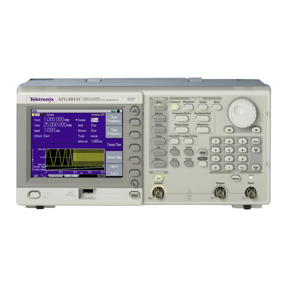
Operating Basics The AFG3000 Series Arbitrary/Function Generators front panel is divided into easy to use functional areas. This section provides you with a quick overview of the controls. Figure 1-1 shows the front panel of dual-channel model. 3102 DUAL CHANNEL 1GS/s Function Run Mode... -
Page 20: Figure 1-2: Front Panel Controls
Operating Basics Front Panel Controls This section introduces you to the front panel controls of the instrument and provides a brief overview on how to use the front panel key controls. Figure 1-2: Front panel controls The AFG3000 Series Arbitrary/Function Generators front-panel key controls are divided into the following categories: Action buttons Menu buttons... - Page 21 Operating Basics Action Buttons The Power (not shown in Figure 1-2), Upper Menu, Top Menu, View, and Manual Trigger buttons are called action buttons. When you push these action buttons, it will cause an action. Power button. Pushing the power button once turns the instrument on. Pushing the power button when the instrument is on will turn off the instrument.
-
Page 22: Figure 1-3: Waveform Parameter And Graph Display
Operating Basics View Format 1. Figure 1-3 is a single channel parameter and graph setup display. In this view, Channel 1 is selected with the Channel Select button. When Channel 2 is selected, the parameters and graph for Channel 2 will be displayed in this view. You can easily toggle between the information for Channel 1 and Channel 2 with this view. -
Page 23: Figure 1-5: Waveform Parameter Comparison (Ch1 Selected)
Operating Basics View Format 3. Figure 1-5 is a channel compare view. In this view, Channel 1 is selected with the Channel Select button. Figure 1-5: Waveform parameter comparison (CH1 selected) In Figure 1-6, Channel 2 is selected with the Channel Select button. Figure 1-6: Waveform parameter comparison (CH2 selected) Manual Trigger button. - Page 24 Operating Basics Other Action buttons. The Enter button and the following related buttons are also classified as Action buttons. Enter button. The Enter button causes a numeric input to be updated. +/– button. This button is only active when you are setting a value. The +/– button changes the sign of the currently selected parameter from positive to negative.
- Page 25 Operating Basics State Buttons The Channel Select, CH1/CH2 Output and Run Mode buttons are called State buttons. Channel Select button. The Channel Select button directly controls the display, toggling between the two channels. This button is used to select the channel that you are currently interacting with.
-
Page 26: Figure 1-7: Run Mode Menu (Continuous)
Operating Basics Select the Run Mode Menu bezel button from the default screen (see page 1-14) to display the Run Mode menus. The Continuous mode is selected in Figure 1-7. If you select Modulation, Sweep, or Burst as the Run Mode, the corresponding bezel menu is highlighted. - Page 27 Operating Basics Shortcut Buttons The following six buttons are called Shortcut buttons and are provided as shortcuts for experienced users. You can push this button while viewing any of the display types. If you are not in view format 1, 2, or 3 (see page 1-3), pushing the shortcut button will take you to the last view you used and highlight the selected setting.
- Page 28 Operating Basics BNC Connectors Refer to Figure 1-2 on page 1-2 for the locations of the front panel BNC connec- tors. CH1 Output. This BNC connector will output the Channel 1 signal. This connector will be deactivated when the Channel 1 output button is not selected. The load impedance for this connection can be set in the Output Menu.
-
Page 29: Display Area And Screen Interface
Operating Basics Display Area and Screen Interface Figure 1-8 shows the main areas of the instrument display. Message display area Numeric input is available Knob is available Main display Output status area Bezel menu Level meter View tab Figure 1-8: Screen interface Main Display Area Pushing the front-panel View button changes the view format of the main display area. -
Page 30: Figure 1-9: Level Meter
Operating Basics Level Meter. Amplitude level is displayed. To protect your DUT (device under test), use the Output Menu to set the limit values for high level and low level. Figure 1-9 shows Level Meter. Figure 1-9: Level meter 1. Shows maximum amplitude level of your instrument. 2. -
Page 31: Figure 1-10: Graphical Representation Of Button Status
Operating Basics Bezel Menu Display Area When you push a front panel button, the instrument displays the corresponding menu on the right side of the screen. The menu shows the options that are available when you push the unlabeled bezel buttons directly to the right of the screen. (Some documentation may also refer to the bezel buttons as side-menu buttons or soft keys.) The AFG3000 Series Arbitrary/Function Generators use four types of menu button... -
Page 32: Waveform Parameters And Numeric Input
Operating Basics Waveform Parameters and Numeric Input This section explains how to set or change the waveform parameters of the arbitrary/function generator using the front-panel controls or bezel menu selection. Changing Parameters The arbitrary/function generator outputs a sine waveform of 1 MHz frequency with Using the Bezel Menu by default. -
Page 33: Figure 1-13: Screen Display With Frequency Active
Operating Basics Numeric Input If you want to change the frequency value, push the Frequency bezel button. The value of Freq in main display area changes to “selected status”. The Freq is displayed in black type inside a white box. See Figure 1-13. Frequency is selected (active). -
Page 34: Figure 1-16: Screen Display With Frequency Active
Operating Basics You can also change the value with the front-panel numeric key-pad. Entering any value from the numeric key-pad will automatically change the bezel menu to Units. See Figure 1-16. The bezel menu is changed to “Units”. The value “2” is entered. Figure 1-16: Screen display with Frequency active (4) After entering the frequency value, push the Units bezel button or the front-panel Enter button to complete the entry. -
Page 35: Figure 1-18: Pwm Sample Screen
Operating Basics Changing Parameters The shortcut buttons are provided for experienced users. The buttons allow you to Using the Shortcut select a setup parameter without using any bezel menu selection. The following Buttons example shows how the Frequency/Period shortcut button works. You can use the shortcut buttons while viewing any of the display formats. -
Page 36: Figure 1-20: Pwm Parameter Menu (Period Is Selected)
Operating Basics You can now change the frequency value. If you push the Frequency/Period shortcut button again, the active parameter will change to Period. See Figure 1-20. Period is active. Figure 1-20: PWM parameter menu (Period is selected) The Frequency/Period shortcut button is used to select the setting that was last used (Frequency or Period). -
Page 37: Rear Panel
Operating Basics Rear Panel Figure 1-21 shows the locations of the instrument rear panel connectors. Security slot ADD INPUT Chassis ground screw GPIB EXT REF OUT EXT REF INPUT EXT MODULATION CH2 INPUT EXT MODULATION CH1 INPUT Figure 1-21: Rear panel connectors EXT REF INPUT. - Page 38 Operating Basics USB. The USB connector is used to connect a USB controller. LAN. This connector is used to connect the arbitrary/function generator to a network. Connect a 10BASE-T or 100BASE-T cable here. GPIB. The GPIB connector is used to control the arbitrary/function generator through remote commands.
- Page 39 Reference...
-
Page 41: Reference
Reference This section describes the menus associated with each front-panel menu button or control. Menu System The user interface of the AFG3000 Series Arbitrary/Function Generators was designed for easy access to specialized functions through the menu structure. When you push a front panel-button, the arbitrary/function generator displays the corresponding menu on the right side of the screen. -
Page 42: Menu Structure
Reference Menu Structure This section describes the menus and operating details associated with each front-panel menu button. Sine/Square Menu, page 2-3 Ramp Menu, page 2-4 Pulse Menu, page 2-4 Arb Menu, page 2-5 More... Menu, page 2-6 Run Mode Menus Continuous (No bezel menu for Continuous mode) Modulation Parameter Menu, page 2-7 Sweep Parameter Menu, page 2-9... -
Page 43: Table 2-1: Sine/Square Menu
Reference Sine/Square Menu Table 2-1 shows the Sine and Square menu. Table 2-1: Sine/Square Menu First Level Second Level Third Level Description Frequency/Period/ Frequency Selects Frequency as a Phase Menu parameter to be changed. Period Selects Period as a parameter to be changed. -
Page 44: Table 2-2: Ramp Menu
Reference Ramp Menu Table 2-2 shows the Ramp menu. Table 2-2: Ramp Menu First Level Second Level Description Ramp Parameter Symmetry Sets the Ramp waveform symmetry to your Menu desired value. Set to 0% Sets the Ramp waveform symmetry to 0%. Set to 50% Sets the Ramp waveform symmetry to 50%. -
Page 45: Table 2-4: Arb Menu
Reference Arb Menu The arbitrary/function generator can output a user-defined waveform that is stored in the internal memory, Edit Memory, or a USB memory. Table 2-4 shows the Arb menu. Table 2-4: Arb Menu First Level Second Level Description Arb Waveform Menu Memory Selects a memory type. -
Page 46: Table 2-5: More Menu
Reference More... Menu Table 2-5 shows the More... menu. Table 2-5: More Menu First Level Second Level Description More Waveform Menu Sin(x)/x Option buttons Noise Gaussian -more- (1 of 2) Lorentz Option buttons Exponential Rise Exponential Decay Haversine -more- (2 of 2) Frequency/Period/ Refer to Table 2-1 Phase Menu... -
Page 47: Table 2-6: Modulation Parameter Menu
Reference Modulation Parameter Table 2-6 shows the Modulation Parameter Menu. Menu Table 2-6: Modulation Parameter Menu First Level Second Level Description Modulation Selects modulation type. Type [AM] [AM] Source Selects modulation source (internal or external) Internal for AM, FM, PM, FSK, or PWM. External AM, FM, PM, PWM Sets modulation frequency or FSK rate. - Page 48 Reference Phase Modulation. Phase modulation is similar to FM (Frequency modulation), but in PM, the phase of the carrier waveform is varied by the amplitude of the modu- lating waveform. Frequency Shift Keying. Frequency shift keying modulation is a modulation tech- nique that shifts the output signal frequency between two frequencies: the carrier frequency and the FSK Hop frequency.
-
Page 49: Figure 2-1: Sweep Type
Reference Sweep Parameter Menu Table 2-7 shows the Sweep Parameter Menu. Table 2-7: Sweep Parameter Menu First Level Description Start Frequency Numeric input. Sets start frequency. Stop Frequency Numeric input. Sets stop frequency. Sweep Time Numeric input. Sets sweep time. Return Time Numeric input. -
Page 50: Figure 2-2: Frequency Sweep
Reference When sweep is taking place, the frequency sweeps from start frequency to stop fre- quency. Refer to Figure 2-2. Frequency Stop freq. Frequency span Center frequency Start freq. Time Sweep time Hold time Return time Figure 2-2: Frequency sweep The instrument sweeps from a low frequency to a high frequency when start fre- quency is set to be lower than stop frequency (start frequency <... -
Page 51: Table 2-8: Burst Parameter Menu
Reference Burst Parameter Menu Table 2-8 shows the Burst Parameter Menu. Table 2-8: Burst Parameter Menu First Level Description 1-Cycle Sets burst count to 1. N-Cycle Sets burst count to N. (N=1 to 1,000,000) Inf-Cycle Sets burst count to Infinite. Gate Selects gated burst mode. -
Page 52: Table 2-9: Output Menu
Reference Output Menu Table 2-9 shows the Output Menu. To access the Output menu, push the front-panel Top Menu button, and then push the bottom bezel button. Table 2-9: Output Menu First Level Second Level Description 50 Ω Option buttons. Set the load impedance to 50 Ω. Load Impedance Load Option buttons &... -
Page 53: Table 2-10: Save/Recall Menu
Reference Save/Recall Menu The Save and Recall menus store or recall arbitrary/function generator setups. The setups are stored in either internal setup memory or USB memory. Table 2-10: Save/Recall Menu Save or Recall First Level Second Level Description Save Memory Selects a memory type Internal (Internal or USB). -
Page 54: Table 2-11: Edit Menu
Reference Edit Menu The Edit menu is used to create or edit user-defined waveforms and to import or export waveforms. To output a user-defined waveform, waveform data must be created in the Edit Memory and then stored in the internal or a USB memory. Although you can output the content of Edit Memory, the content of Edit Memory will be deleted when the instrument is powered off. - Page 55 Reference Table 2-11: Edit Menu (cont.) First Level Second Level Description Paste at Beginning Memory Selects a memory type (Internal or USB). Internal Paste Pastes a waveform at the beginning of the current waveform. (blank) Change Directory Opens a directory. This menu item is available when USB is selected.
-
Page 56: Figure 2-3: Number Of Points
Reference Number of Points. This bezel menu sets the number of points of the waveform to be created or the length of Edit Memory. The point can be set to a value in the follow- ing range: 2 to 65,536 (AFG3021 and AFG3022) 2 to 131,072 (AFG3101/AFG3102 and AFG3251/AFG3252) If a waveform is already written to Edit Memory and Number of Points is set to a value smaller than the number of points in that waveform, then the data for the... -
Page 57: Table 2-12: Operations Submenu
Reference New. Pushing the New bezel button will display a standard waveform selection submenu. You can select a standard waveform from five waveform types (Sine, Square, Pulse, Ramp, and Noise). For example, selecting Sine will write a sine waveform into Edit Memory. The waveform has the number of points specified by the Number of Points bezel menu. -
Page 58: Figure 2-4: Using The Cursor (Line Edit)
Reference Using the Cursors. You can use cursors to edit a waveform. To use cursors, select the Operations submenu in the Edit menu. Figure 2-4 is a sample of Line edit screen. Figure 2-4: Using the Cursor (Line edit) In the Line edit screen, there are two cursor types: X1 cursor and X2 cursor. Use the From X1 or To X2 bezel button to select which cursor to move. -
Page 59: Figure 2-5: Line Edit Example
Reference Line (Line Edit). The Line edits by linearly interpolating from a specified point in the waveform currently edited to another specified point as shown in Figure 2-5. Before executing Line edit After executing Line edit Figure 2-5: Line Edit example Data (Edit by Data Point). -
Page 60: Figure 2-7: Cut Example
Reference Cut (Cut by Data Points). The Cut deletes an area between specified points in the waveform. When Cut is selected, two values can be input (From X1 and To X2). See Figure 2-7. Before executing Cut After executing Cut Figure 2-7: Cut example Data that has been deleted cannot be recovered. -
Page 61: Figure 2-8: Paste At Beginning
Reference Paste at Beginning. The Paste at Beginning inserts the contents of the user wave- form memory (User1, User2, User3, or User4), USB memory, or the current contents of Edit Memory at the beginning of the waveform that is currently being edited. -
Page 62: Figure 2-9: Paste At End
Reference Paste at End. The Paste at End appends the contents of the user waveform memory (User1, User2, User3, or User4), USB memory, or the current contents of edit memory at the end of the waveform currently being edited. When this opera- tion is executed, the Number of Points setting is automatically modified. -
Page 63: Table 2-13: Utility Menu
Reference Utility Menu The Utility menu provides access to utilities used by the arbitrary/function gener- ator such as language selection, instrument diagnostics, and user preferences. Table 2-13: Utility Menu First Level Second Level Third Level Description I/O Interface GPIB Address Sets the instrument GPIB address. - Page 64 Reference Table 2-13: Utility Menu (cont.) First Level Second Level Third Level Description System Trigger Out Select Trigger to generate the trigger signal for Trigger the oscilloscope. Sync Select Sync to synchronize multiple AFG3000 series instruments. Clock Ref Select Internal to accept the internal reference Internal clock.
- Page 65 Reference Table 2-13: Utility Menu (cont.) First Level Second Level Third Level Description Diagnostics/ Execute Diagnostics Performs the instrument diagnostics. Calibration Execute Calibration Performs the instrument self calibration. Backup/ Type Selects file type (Setup or Arb). Restore Setup Backup Copies the contents of internal memory to a Internal ->...
- Page 66 Reference Synchronous Operation. By synchronizing multiple arbitrary/function generators, you can configure the multichannel arbitrary/function generator. To synchronize multiple arbitrary/function generators, connect the instruments as follows: Use a BNC cable to connect the front-panel Trigger Output connector of the master unit and the Trigger Input connector of the slave unit. Use another BNC cable to connect the EXT REF OUTPUT connector on the rear panel of the master unit and the EXT REF INPUT connector of the slave unit.
- Page 67 Firmware Update. You can use the Utility menu to update your arbitrary/function generator instrument firmware. If Tektronix offers a newer version of firmware, download the firmware file to your USB memory from the Tektronix Web site. 1. Go to www.tektronix.com.
-
Page 68: File Operations
Reference File Operations This section describes the basic file operations such as browsing files and saving or recalling the instrument setups or waveform data. The instrument setups or the waveform data can be saved in or recalled from files in the internal memory or a USB memory. - Page 69 Reference Browsing Waveform Files using Edit Menu. You can also browse through wave- forms using the Edit Menu. Select a file you want to edit and then push the Read bezel button. The specified waveform is loaded to the Edit Memory. You can now edit the waveform.
-
Page 70: Figure 2-11: Write As - Character Entry Box
Reference Entering a File Name. When you select Write As from the Write to... submenu, the character entry box is displayed as shown in Figure 2-11. File name box Figure 2-11: Write As - Character entry box English alphabet characters are displayed below the file name box. A selected char- acter is highlighted. -
Page 71: Figure 2-12: Recall Menu (Internal)
Reference Browsing Instrument To browse instrument setup files in the internal memory or in a USB memory, push Setup Files the front-panel Recall button, and then push the Memory bezel button to specify Internal or USB as a memory type. Figure 2-12 is an example of screen when Internal is selected. -
Page 72: Figure 2-13: Save As - Character Entry Box
Reference Entering a File Name. When you select Save As, the file name box is displayed as shown in Figure 2-13. File name box Figure 2-13: Save As - Character entry box English alphabet characters are displayed below the file name box. A selected char- acter is highlighted. - Page 73 Syntax and Commands...
-
Page 75: Syntax And Commands
Syntax and Commands This section provides the following information: Command Syntax defines the command syntax and processing conventions. Command Groups describes command groups which lists the commands by function. Command Descriptions describes the notation of each of the commands in alphabetical order. -
Page 76: Table 3-2: Command Message Elements
Syntax and Commands Command and Query Commands consist of set commands and query commands (usually simply called Structure commands and queries). Commands change instrument settings or perform a specific action. Queries cause the instrument to return data and information about its status. -
Page 77: Figure 3-1: Command Message Elements
Syntax and Commands Figure 3-1 shows the five command message elements. Comma Header MMEMory:STATe:LOCK 1, ON Arguments Mnemonics Space Figure 3-1: Command message elements Commands. Commands cause the instrument to perform a specific function or change one of its settings. Commands have the structure: [:]<Header>[<Space><Argument>[<Comma><Argument>]...] A command header is made up of one or more mnemonics arranged in a hierar- chical or tree structure. -
Page 78: Figure 3-2: Example Of Scpi Subsystem Hierarchy Tree
Syntax and Commands Command Entry Follow these general rules when entering commands: Enter commands in upper or lower case. You can precede any command with white space characters. White space char- acters include any combination of the ASCII control characters 00 through 09 and 0B through 20 hexadecimal (0 through 9 and 11 through 32 decimal). -
Page 79: Table 3-4: Parameter Types Used In Syntax Descriptions
Syntax and Commands Creating Commands SCPI commands are created by stringing together the nodes of a subsystem hier- archy and separating each node by a colon. In Figure 3-2, TRIGger is the root node and SEQuence, SLOPe, SOURce, and TIMer are lower level nodes. -
Page 80: Figure 3-3: Example Of Abbreviating A Command
Syntax and Commands Special Characters The Line Feed (LF) character or the New Line (NL) character (ASCII 10), and all characters in the range of ASCII 127-255 are defined as special characters. These characters are used in arbitrary block arguments only; using these characters in other parts of any command yields unpredictable results. -
Page 81: Figure 3-4: Example Of Chaining Commands And Queries
Syntax and Commands Chaining Commands and You can chain several commands or queries together into a single message. To Queries create a chained message, first create a command or query, then add a semicolon (;), and finally add more commands or queries and semicolons until you are done. If the command following a semicolon is a root node, precede it with a colon (:). - Page 82 Syntax and Commands General Rules for Using The following are three general rules for using SCPI commands, queries, and SCPI commands parameters: You can use single (‘ ’) or double (“ ”) quotation marks for quoted strings, but you cannot use both types of quotation marks for the same string. correct “This string uses quotation marks correctly.”...
-
Page 83: Command Groups
Syntax and Commands Command Groups This section lists the commands organized by functional group. The Command Descriptions section, starting on page 3-15, lists all commands alphabetically. Calibration and Diagnostic Commands. Calibration and Diagnostic commands let you initiate the instrument self-calibration routines and examine the results of diag- nostic tests. -
Page 84: Table 3-8: Mass Memory Commands
Syntax and Commands Mass Memory Commands. Mass Memory commands let you change mass memory attributes. Table 3-8 lists and describes Mass Memory commands. Table 3-8: Mass Memory commands Header Description MMEMory:CATalog? Query the status of mass memory MMEMory:CDIRectory Set/query current directory MMEMory:DELete Delete file or directory in mass memory MMEMory:LOAD:STATe... - Page 85 Syntax and Commands Table 3-10: Source commands (cont.) Header Description [SOURce[1|2]]:BURSt [:STATe] Set/query burst mode status [SOURce[1|2]]:COMBine:FEED Set/query internal noise or external signal [SOURce[1|2]]:FM:INTernal:FREQuency Set/query internal modulation frequency [SOURce[1|2]]:FM:INTernal:FUNCtion Set/query internal modulation waveform [SOURce[1|2]]:FM:INTernal:FUNCtion:EFILe Set/query EFILe setting [SOURce[1|2]]:FM:SOURce Set/query frequency modulation source [SOURce[1|2]]:FM:STATe Set/query frequency modulation status [SOURce[1|2]]:FM [:DEViation]...
-
Page 86: Table 3-11: Status Commands
Syntax and Commands Table 3-10: Source commands (cont.) Header Description [SOURce[1|2]]:PWM:INTernal:FREQuency Set/query pulse width modulation frequency [SOURce[1|2]]:PWM:INTernal:FUNCtion Set/query pulse width modulation waveform [SOURce[1|2]]:PWM:INTernal:FUNCtion:EFILe Set/query EFILe name [SOURce[1|2]]:PWM:SOURce Set/query pulse width modulation source [SOURce[1|2]]:PWM:STATe Set/query pulse width modulation status [SOURce[1|2]]:PWM [:DEViation]:DCYCle Set/query pulse width modulation deviation [SOURce[1|2]]:SWEep:HTIMe Set/query sweep hold time... -
Page 87: Table 3-12: System Commands
Syntax and Commands Table 3-11: Status commands (cont.) Header Description STATus:QUEStionable[:EVENt]? Return questionable event register STATus:QUEStionable:CONDition? Return questionable condition register STATus:QUEStionable:ENABle Set/query questionable enable register System Commands. System commands let you control miscellaneous instrument functions. Table 3-12 lists and describes System commands. Table 3-12: System commands Header Description... -
Page 88: Table 3-14: Trace Commands
Syntax and Commands Trace Commands. Trace commands let you set the edit memory and user waveform memory. Table 3-14 lists and describes Trace commands. Table 3-14: Trace commands Header Description TRACe|DATA:CATalog? Return user waveform memory status TRACe|DATA:COPY Copy edit memory (or user waveform memory) content to user waveform memory (or edit memory) TRACe|DATA[:DATA] Set/query waveform data to edit memory... -
Page 89: Command Descriptions
Syntax and Commands Command Descriptions Commands either set or query instrument values. Some commands both set and query, some only set, and some only query. Manual Conventions This manual uses the following conventions: No Query Form indicates set-only commands A question mark (?) appended to the commands and Query Only indicates query-only commands Fully spells out headers, mnemonics, and arguments with the minimal spelling shown in upper case;... -
Page 90: Afgcontrol:cscopy (No Query Form)
Syntax and Commands AFGControl:CSCopy (No Query Form) This command copies setup parameters for one channel to another channel. If your arbitrary/function generator is a single-channel model, this command is not supported. Group AFG Control Syntax AFGControl:CSCopy {CH1|CH2},{CH1|CH2} Arguments CH1|CH2 Examples AFGControl:CSCopy CH1,CH2 copies the CH1 setup parameters into CH2. -
Page 91: Calibration[:All]
Syntax and Commands CALibration[:ALL] The CALibration[:ALL] command performs an internal calibration. The CALibration[:ALL]? command performs an internal calibration and returns 0 (Pass) or a calibration error code. The self-calibration can take several minutes to complete. During this time, NOTE. the arbitrary/function generator does not execute any commands. Do not power off the instrument during the self-calibration. -
Page 92: Diagnostic[:All]
Syntax and Commands DIAGnostic[:ALL] The DIAGnostic[:ALL] command performs a self-test. The DIAGnostic[:ALL]? command returns the results after executing the test. The self-test can take several minutes to complete. During this time, the NOTE. arbitrary/function generator does not execute any commands. Do not power off the instrument during the self-test. -
Page 93: Display:contrast
Syntax and Commands DISPlay:CONTrast This command sets or queries the contrast of the LCD display. Group Display Syntax DISPlay:CONTrast {<contrast>|MINimum|MAXimum} DISPlay:CONTrast? [MINimum|MAXimum] Arguments <contrast>::=<NR2> where <NR2> is a range of display contrast from 0 through 1. The larger the value, the greater the screen contrast. -
Page 94: Display[:Window]:Text[:Data]
Syntax and Commands DISPlay[:WINDow]:TEXT[:DATA] The DISPlay[:WINDow]:TEXT[:DATA] command displays a text message on the instrument screen. The DISPlay[:WINDow]:TEXT[:DATA]? command returns a text string currently displayed on the instrument screen. The displayable characters are ASCII code 32 through 126, and the instrument can display approximately 64 characters. - Page 95 Syntax and Commands *ESE This command sets or queries the bits in the Event Status Enable Register (ESER) used in the status and events reporting system of the arbitrary/function generator. The query command returns the contents of the ESER. Group Status Related Commands *CLS, *ESR?, *PSC, *SRE, *STB...
-
Page 96: Esr?
This query-only command returns identification information on the arbitrary/func- tion generator. Group System Syntax *IDN? Arguments None Returns <Manufacturer>,<Model>,<Serial Number>,<Firmware Level> where: <Manufacturer>::=TEKTRONIX <Model>::={AFG3021|AFG3022|AFG3101|AFG3102|AFG3251|AFG3252} <Serial Number> <Firmware Level>::=SCPI:99.0 FV:1.0 Examples *IDN? might return the following response: TEKTRONIX,AFG3102,C100101,SCPI:99.0 FV:1.0 3-22 AFG3000 Series Arbitrary/Function Generators Reference Manual... -
Page 97: Memory:state:valid?
Syntax and Commands MEMory:STATe:VALid? This query-only command returns the availability of a setup memory. Group Memory Syntax MEMory:STATe:VALid? {0|1|2|3|4} Arguments 0, 1, 2, 3, or 4 specifies the location of setup memory. Returns <NR1> 1 means that the specified setup memory has been saved. 0 means that the specified setup memory has been deleted. -
Page 98: Memory:state:lock
Syntax and Commands MEMory:STATe:LOCK This command sets or queries whether to lock the specified setup memory. If you lock a setup memory, you cannot overwrite or delete the setup file. You cannot execute this command for the setup memory of location number 0 (last setup memory). -
Page 99: Memory:state:recall:auto
Syntax and Commands MEMory:STATe:RECall:AUTo This command sets or queries whether to enable the automatic recall of last setup memory when powered-on. The next time you apply the power, the arbitrary/func- tion generator will automatically recall the settings you used when you powered off the instrument. -
Page 100: Mmemory:catalog?
Syntax and Commands MMEMory:CATalog? This query-only command returns the current state of the mass storage system (USB memory). Group Mass Memory Related Commands MMEMory:CDIRectory Syntax MMEMory:CATalog? Arguments None Returns <NR1>,<NR1>[,<file_name>,<file_type>,<file_size>]... where: The first <NR1> indicates that the total amount of storage currently used, in bytes. The second <NR1>... -
Page 101: Mmemory:cdirectory
Syntax and Commands MMEMory:CDIRectory This command changes the current working directory in the mass storage system. Group Mass Memory Syntax MMEMory:CDIRectory [<directory_name>] MMEMory:CDIRectory? Arguments <directory_name>::=<string> indicates that the current working directory for the mass storage system. If you do not specify a parameter, the directory is set to the *RST value. At *RST, this parameter is set to the root. -
Page 102: Mmemory:load:state (No Query Form)
Syntax and Commands MMEMory:LOAD:STATe (No Query Form) This command copies a setup file in the mass storage system to an internal setup memory. If a specified internal setup memory is locked, this command causes an error. When you power off the instrument, the setups are automatically overwritten in the setup memory 0 (last setup memory). -
Page 103: Mmemory:lock[:State]
Syntax and Commands MMEMory:LOCK[:STATe] This command sets or queries whether to lock a file or directory in the mass storage system. If you lock a file or directory, you cannot overwrite or delete it. Group Mass Memory Syntax MMEMory:LOCK[:STATe]<file_name>,{ON|OFF|<NR1>} MMEMory:LOCK[:STATe]<file_name>? Arguments ON or <NR1>≠0 locks a file or directory in the mass storage system. -
Page 104: Mmemory:store:state (No Query Form)
Syntax and Commands MMEMory:STORe:STATe (No Query Form) This command copies a setup file in the setup memory to a specified file in the mass storage system. If the specified file in the mass storage system is locked, this command causes an error. You cannot create a new file if the directory is locked. If the setup memory is deleted, this command causes an error. -
Page 105: Opt?
Syntax and Commands *OPC This command generates the operation complete message by setting bit 0 in the Standard Event Status Register (SESR) when all pending commands that generate an OPC message are complete. The query command places the ASCII character “1” into the output queue when all such OPC commands are complete. -
Page 106: Output[1|2]:Impedance
Syntax and Commands OUTPut[1|2]:IMPedance The OUTPut:IMPedance command sets the output load impedance for the specified channel. The specified value is used for amplitude, offset, and high/low level settings. You can set the impedance to any value from 1 Ω to 10 kΩ . The default value is 50 Ω... -
Page 107: Output[1|2]:Polarity
Syntax and Commands OUTPut[1|2]:POLarity This command inverts a specified output waveform relative to the offset level. The query command returns the polarity for the specified channel. Group Output Syntax OUTPut[1|2]:POLarity{NORMal|INVerted} OUTPut[1|2]:POLarity? Arguments NORMal sets the specified output waveform polarity to Normal. INVerted sets the specified output waveform polarity to Inverted. -
Page 108: Output:trigger:mode
Syntax and Commands OUTPut:TRIGger:MODE This command sets or queries the mode (trigger or sync) for Trigger Output signal. When the burst count is set to Inf-Cycles in burst mode, TRIGger indicates that the infinite number of cycles of waveform will be output from the Trigger Output connector. -
Page 109: Rcl (No Query Form)
Syntax and Commands *PSC This command sets and queries the power-on status flag that controls the automatic power-on execution of SRER and ESER. When *PSC is true, SRER and ESER are set to 0 at power-on. When *PSC is false, the current values in the SRER and ESER are preserved in nonvolatile memory when power is shut off and are restored at power-on. -
Page 110: Rst (No Query Form)
Syntax and Commands *RST (No Query Form) This command resets the instrument to the factory default settings. This command is equivalent to pushing the Default button on the front panel. The default values are listed in Default Settings on page D-1. Group System Syntax... -
Page 111: Source[1|2]]:Am[:Depth]
Syntax and Commands [SOURce[1|2]]:AM[:DEPTh] This command sets or queries the modulation depth of AM modulation for the specified channel. Group Source Syntax [SOURce[1|2]]:AM:DEPTh{<depth>|MINimum|MAXimum} [SOURce[1|2]]:AM:DEPTh?[MINimum|MAXimum] Arguments <depth>::=<NR2>[<units>] where <NR2> is the depth of modulating frequency. <units>::=PCT MINimum sets the modulation depth to minimum value. MAXimum sets the modulation depth to maximum value. -
Page 112: Source[1|2]]:Am:internal:frequency
Syntax and Commands [SOURce[1|2]]:AM:INTernal:FREQuency This command sets or queries the internal modulation frequency of AM modula- tion for the specified channel. You can use this command only when the internal modulation source is selected. You can select the source of modulating signal by using the [SOURce[1|2]]:AM:SOURce [INTernal|EXTernal] command. -
Page 113: Source[1|2]]:Am:internal:function
Syntax and Commands [SOURce[1|2]]:AM:INTernal:FUNCtion This command sets or queries the modulating waveform of AM modulation for the specified channel. You can use this command only when the internal modulation source is selected. If you specify EFILe when there is no EFILe or the EFILe is not yet defined, this command causes an error. -
Page 114: Source[1|2]]:Am:internal:function:efile
Syntax and Commands [SOURce[1|2]]:AM:INTernal:FUNCtion:EFILe This command sets or queries an EFILe name used as a modulating waveform for AM modulation. A file name must be specified in the mass storage system. This command causes an error if there is no file in the mass storage. Group Source Syntax... -
Page 115: Source[1|2]]:Am:state
Syntax and Commands [SOURce[1|2]]:AM:STATe This command enables or disables AM modulation for the specified channel. The query command returns the state of AM modulation. Group Source Syntax [SOURce[1|2]]:AM:STATe {ON|OFF|<NR1>} [SOURce[1|2]]:AM:STATe? Arguments ON or <NR1>≠0 enables AM modulation. OFF or <NR1>=0 disables AM modulation. Returns <NR1>... -
Page 116: Source[1|2]]:Burst:ncycles
Syntax and Commands [SOURce[1|2]]:BURSt:NCYCles This command sets or queries the number of cycles (burst count) to be output in burst mode for the specified channel. The query command returns 9.9E+37 if the burst count is set to INFinity. Group Source Syntax [SOURce[1|2]]:BURSt:NCYCles {<cycles>|INFinity|MINimum|MAXimum} [SOURce[1|2]]:BURSt:NCYCles? {MINimum|MAXimum}... -
Page 117: Source[1|2]]:Burst[:State]
Syntax and Commands [SOURce[1|2]]:BURSt[:STATe] This command enables or disables the burst mode for the specified channel. The query command returns the state of burst mode. Group Source Syntax [SOURce[1|2]]:BURSt:STATe {ON|OFF|<NR1>} [SOURce[1|2]]:BURSt:STATe? Arguments ON or <NR1>≠0 enables the burst mode. OFF or <NR1>=0 disables the burst mode. Returns <NR1>... -
Page 118: Source[1|2]]:Burst:tdelay
Syntax and Commands [SOURce[1|2]]:BURSt:TDELay This command sets or queries delay time in the burst mode for the specified channel. It specifies a time delay between the trigger and the signal output. This command is available only in the Triggered burst mode. Group Source Syntax... -
Page 119: Source[1|2]]:Combine:feed
Syntax and Commands [SOURce[1|2]]:COMBine:FEED This command sets or queries whether to add the internal noise or an external signal to an output signal for the specified channel. When you specify the internal noise, you can set or query the noise level by SOURce<3|4>:POWer[:LEVel][:IMMediate][:AMPLitude] command. -
Page 120: Source[1|2]]:Fm[:Deviation]
Syntax and Commands [SOURce[1|2]]:FM[:DEViation] This command sets or queries the peak frequency deviation of FM modulation for the specified channel. The setting range of frequency deviation depends on the waveform selected as the carrier. Group Source Syntax [SOURce[1|2]]:FM:DEViation {<deviation>|MINimum|MAXimum} [SOURce[1|2]]:FM:DEViation?{MINimum|MAXimum} Arguments <deviation>::=<NRf>[<units>] where... -
Page 121: Source[1|2]]:Fm:internal:function
Syntax and Commands [SOURce[1|2]]:FM:INTernal:FUNCtion This command sets or queries the modulating waveform of FM modulation for the specified channel. You can use this command only when the internal modulation source is selected. If you specify EFILe when there is no EFILe or the EFILe is not yet defined, this command causes an error. -
Page 122: Source[1|2]]:Fm:internal:function:efile
Syntax and Commands [SOURce[1|2]]:FM:INTernal:FUNCtion:EFILe This command sets or queries an EFILe name used as a modulating waveform for FM modulation. A file name must be specified in the mass storage system. This command causes an error if there is no file in the mass storage. Group Source Syntax... -
Page 123: Source[1|2]]:Fm:state
Syntax and Commands [SOURce[1|2]]:FM:STATe This command enables or disables FM modulation. The query command returns the state of FM modulation. Group Source Syntax [SOURce[1|2]]:FM:STATe {ON|OFF|<NR1>} [SOURce[1|2]]:FM:STATe? Arguments ON or <NR1>≠0 enables FM modulation. OFF or <NR1>=0 disables FM modulation. Returns <NR1>... -
Page 124: Source[1|2]]:Frequency:concurrent[:State]
Syntax and Commands [SOURce[1|2]]:FREQuency:CONCurrent[:STATe] This command enables or disables the function to copy the frequency (or period) of one channel to another channel. The[SOURce[1|2]]:FREQuency:CONCurrent command copies the frequency (or period) of the channel specified by the header suffix to another channel. If you specify CH 1 with the header, the CH 1 frequency will be copied to CH 2. -
Page 125: Source[1|2]]:Frequency[:Cw|:Fixed]
Syntax and Commands [SOURce[1|2]]:FREQuency[:CW|:FIXed] This command sets or queries the frequency of output waveform for the specified channel. This command is available when the Run Mode is set to other than Sweep. The setting range of output frequency depends on the type of output waveform. If you change the type of output waveform, it might change the output frequency because changing waveform types impacts on the setting range of output frequency. -
Page 126: Source[1|2]]:Frequency:mode
Syntax and Commands [SOURce[1|2]]:FREQuency:MODE This command sets or queries the frequency sweep state. You can select sine, square, ramp, or arbitrary waveform for sweep. The arbitrary/function generator automatically changes to the Continuous mode if any waveform is selected other than sine, square, ramp, or an arbitrary waveform. Group Source Related Commands... -
Page 127: Source[1|2]]:Frequency:span
Syntax and Commands [SOURce[1|2]]:FREQuency:SPAN This command sets or queries the span of frequency sweep for the specified channel. This command is always used with the [SOURce[1|2]]:FREQuency:CENTer command. The setting range of frequency span depends on the waveform selected for sweep. Group Source Related Commands... -
Page 128: Source[1|2]]:Frequency:start
Syntax and Commands [SOURce[1|2]]:FREQuency:STARt This command sets or queries the start frequency of sweep for the specified channel. This command is always used with the [SOURce[1|2]]:FREQuency:STOP command. The setting range of start frequency depends on the waveform selected for sweep. Group Source Related Commands... -
Page 129: Source[1|2]]:Frequency:stop
Syntax and Commands [SOURce[1|2]]:FREQuency:STOP This command sets or queries the start frequency of sweep for the specified channel. This command is always used with the [SOURce[1|2]]:FREQuency:STARt command. The setting range of stop frequency depends on the waveform selected for sweep. Group Source Related Commands... -
Page 130: Source[1|2]]:Fskey[:Frequency]
Syntax and Commands [SOURce[1|2]]:FSKey[:FREQuency] This command sets or queries the hop frequency of FSK modulation for the spec- ified channel. Group Source Syntax [SOURce[1|2]]:FSKey[:FREQuency] {<frequency>|MINimum|MAXimum} [SOURce[1|2]]:FSKey[:FREQuency]? {MINimum|MAXimum} Arguments <frequency>::=<NRf>[<units>] where <NRf> is the hop frequency. <units>::=[Hz | kHz | MHz] Returns <frequency>... -
Page 131: Source[1|2]]:Fskey:source
Syntax and Commands [SOURce[1|2]]:FSKey:SOURce This command sets or queries the source of modulation signal of FSK modulation for the specified channel. Group Source Syntax [SOURce[1|2]]:FSKey:SOURce [INTernal|EXTernal] [SOURce[1|2]]:FSKey:SOURce? Arguments INTernal means that the carrier waveform is modulated with an internal source. EXTernal means that the carrier waveform is modulated with an external source. -
Page 132: Source[1|2]]:Function:efile
Syntax and Commands [SOURce[1|2]]:FUNCtion:EFILe This command sets or queries an EFILe name used as an output waveform. A file name must be specified in the mass storage system. This command causes an error if there is no file in the mass storage. Group Source Syntax... -
Page 133: Source[1|2]]:Function[:Shape]
Syntax and Commands [SOURce[1|2]]:FUNCtion[:SHAPe] This command sets or queries the shape of the output waveform. When the speci- fied user memory is deleted, this command causes an error if you select the user memory. Group Source Syntax [SOURce[1|2]]:FUNCtion[:SHAPe] {SINusoid|SQUare|PULSe|RAMP |PRNoise|DC|SINC|GAUSsian|LORentz|ERISe|EDECay|HAVersine|USER[1]| USER2|USER3|USER4|EMEMory|EFILe} [SOURce[1|2]]:FUNCtion[:SHAPe]? Arguments... -
Page 134: Source[1|2]]:Phase[:Adjust]
Syntax and Commands EFILe EFILe is specified as an output waveform. Returns SIN|SQU|PULS|RAMP|PRN|DC|SINC|GAUS|LOR|ERIS|EDEC|HARV|USER1|USER2 |USER3|USER4|EMEMory|EFILe Examples SOURce1:FUNCtion:SHAPe SQUare selects the shape of CH 1 output waveform to square waveform. [SOURce[1|2]]:PHASe[:ADJust] This command sets or queries the phase of output waveform for the specified channel. -
Page 135: Source[1|2]]:Phase:initiate (No Query Form)
Syntax and Commands [SOURce[1|2]]:PHASe:INITiate (No Query Form) This command synchronizes the phase of CH 1 and CH 2 output waveforms. The arbitrary/function generator performs the same operation if you specify either SOURce1 or SOURce2. If your arbitrary/function generator is single-channel model, this command is not supported. -
Page 136: Source[1|2]]:Pm:internal:frequency
Syntax and Commands [SOURce[1|2]]:PM:INTernal:FREQuency This command sets or queries the internal modulation frequency of PM modulation for the specified channel. You can use this command only when the internal modu- lation source is selected. Group Source Related Commands [SOURce[1|2]]:PM:SOURce Syntax [SOURce[1|2]]:PM:INTernal:FREQuency {<frequency>|MINimum|MAXimum} [SOURce[1|2]]:PM:INTernal:FREQuency?[MINimum|MAXimum] Arguments... -
Page 137: Source[1|2]]:Pm:internal:function
Syntax and Commands [SOURce[1|2]]:PM:INTernal:FUNCtion This command sets or queries the modulating waveform of PM modulation for the specified channel. You can use this command only when the internal modulation source is selected. If you specify EFILe when there is no EFILe or the EFILe is not yet defined, this command causes an error. -
Page 138: Source[1|2]]:Pm:internal:function:efile
Syntax and Commands [SOURce[1|2]]:PM:INTernal:FUNCtion:EFILe This command sets or queries an EFILe name used as a modulating waveform for PM modulation. A file name must be specified in the mass storage system. This command causes an error if there is no file in the mass storage. Group Source Syntax... -
Page 139: Source[1|2]]:Pm:state
Syntax and Commands [SOURce[1|2]]:PM:STATe This command enables or disables PM modulation. The query command returns the state of PM modulation.You can select a sine, square, ramp, or arbitrary wave- form for the carrier waveform. Group Source Syntax [SOURce[1|2]]:PM:STATe {ON|OFF|<NR1>} [SOURce[1|2]]:PM:STATe? Arguments ON or <NR1>≠0 enables PM modulation. -
Page 140: Source<3|4>:Power[:Level][:Immediate][:Amplitude]
Syntax and Commands SOURce<3|4>:POWer[:LEVel][:IMMediate][:AMPLitude] This command sets or queries the internal noise level which applies to the output signal for the specified channel. The noise level represents the percent against current amplitude level. The setting range is 0 to 50%. This command is available when Run Mode is set to Continuous, Burst, or Sweep. -
Page 141: Source[1|2]]:Pulse:dcycle
Syntax and Commands [SOURce[1|2]]:PULSe:DCYCle This command sets or queries the duty cycle of the pulse waveform for the speci- fied channel. The setting range is 0.1% to 99.9% in increments of 0.1. The arbitrary/function generator will hold the settings of leading edge and trailing edge when the duty cycle is varied. -
Page 142: Source[1|2]]:Pulse:delay
Syntax and Commands [SOURce[1|2]]:PULSe:DELay This command sets or queries the lead delay of the pulse waveform for the speci- fied channel. Group Source Syntax [SOURce[1|2]]:PULSe:DELay {<delay>|MINimum|MAXimum} [SOURce[1|2]]:PULSe:DELay?{MINimum|MAXimum} Arguments <delay>::=<NR2>[<units>] where <NR2> is the lead delay. <units>::=[ns | µs | ms | s] Setting range: 0 ns to Pulse Period –... -
Page 143: Source[1|2]]:Pulse:period
Syntax and Commands [SOURce[1|2]]:PULSe:PERiod This command sets or queries the period for pulse waveform. Group Source Syntax [SOURce[1|2]]:PULSe:PERiod {<period>|MINimum|MAXimum} [SOURce[1|2]]:PULSe:PERiod?{MINimum|MAXimum} Arguments <period>::=<NRf>[<units>] where <NRf> is the pulse period. <units>::=[ns | µs | ms | s] Returns <period> Examples SOURce1:PULSe:PERiod 200ns sets the CH 1 pulse period to 200 ns. -
Page 144: Source[1|2]]:Pulse:transition:trailing
Syntax and Commands [SOURce[1|2]]:PULSe:TRANsition:TRAiling This command sets or queries the trailing edge time of pulse waveform. Group Source Syntax [SOURce[1|2]]:PULSe:TRANsition:TRAiling {<seconds>|MINimum| MAXimum} [SOURce[1|2]]:PULSe:TRANsition:TRAiling?{MINimum|MAXimum} Arguments <seconds>::=<NRf>[<units>] where <NRf> is the trailing edge of pulse waveform. <units>::=[ns | µs | ms | s] Returns <seconds>... -
Page 145: Source[1|2]]:Pulse:width
Syntax and Commands [SOURce[1|2]]:PULSe:WIDTh This command sets or queries the pulse width for the specified channel. Pulse Width = Period × Duty Cycle / 100 The pulse width must be less than the period. The setting range is 0.1% to 99.9% in terms of duty cycle. -
Page 146: Source[1|2]]:Pwm:internal:frequency
Syntax and Commands [SOURce[1|2]]:PWM:INTernal:FREQuency This command sets or queries the internal modulation frequency of PWM modula- tion for the specified channel. You can use this command only when the internal modulation source is selected. Group Source Related Commands [SOURce[1|2]]:PWM:SOURce Syntax [SOURce[1|2]]:PWM:INTernal:FREQuency {<frequency>|MINimum|MAXimum} [SOURce[1|2]]:PWM:INTernal:FREQuency?[MINimum|MAXimum]... -
Page 147: Source[1|2]]:Pwm:internal:function
Syntax and Commands [SOURce[1|2]]:PWM:INTernal:FUNCtion This command sets or queries the modulating waveform of PWM modulation for the specified channel. You can use this command only when the internal modula- tion source is selected. If you specify EFILe when there is no EFILe or the EFILe is not yet defined, this command causes an error. -
Page 148: Source[1|2]]:Pwm:internal:function:efile
Syntax and Commands [SOURce[1|2]]:PWM:INTernal:FUNCtion:EFILe This command sets or queries an EFILe name used as a modulating waveform for PWM modulation. A file name must be specified in the mass storage system. This command causes an error if there is no file in the mass storage. Group Source Syntax... -
Page 149: Source[1|2]]:Pwm:state
Syntax and Commands [SOURce[1|2]]:PWM:STATe This command enables or disables PWM modulation. The query command returns the state of PWM modulation. You can select only pulse waveform as a carrier waveform for PWM. Group Source Syntax [SOURce[1|2]]:PWM:STATe {ON|OFF|<NR1>} [SOURce[1|2]]:PWM:STATe? Arguments ON or <NR1>≠0 enables PWM modulation. OFF or <NR1>=0 disables PWM modulation. -
Page 150: Source[1|2]]:Pwm[:Deviation]:Dcycle
Syntax and Commands [SOURce[1|2]]:PWM[:DEViation]:DCYCle This command sets or queries the PWM deviation in percent for the specified channel. The setting range must meet the following conditions: Deviation ≤ Pulse Width – PWmin Deviation ≤ Pulse Period – Pulse Width – PWmin Deviation ≤... -
Page 151: Source]:Roscillator:source
Syntax and Commands [SOURce]:ROSCillator:SOURce This command sets the reference clock to either internal or external. Group Source Syntax [SOURce]:ROSCillator:SOURce {INTernal|EXTernal} [SOURce]:ROSCillator:SOURce? Arguments INTernal means that the reference clock is set to internal. EXTernal means that the reference clock is set to external. Returns INT|EXT Examples... -
Page 152: Source[1|2]]:Sweep:mode
Syntax and Commands [SOURce[1|2]]:SWEep:MODE The [SOURce[1|2]]:SWEep:MODE command selects auto or manual for the sweep mode for the specified channel. The query command returns the sweep mode for the specified channel. Group Source Related Commands [SOURce[1|2]]:SWEep:HTIMe [SOURce[1|2]]:SWEep:RTIMe [SOURce[1|2]]:SWEep:TIME TRIGger[:SEQuence]:SOURce TRIGger[:SEQuence]:TIMer Syntax [SOURce[1|2]]:SWEep:MODE {AUTO|MANual} [SOURce[1|2]]:SWEep:MODE? Arguments... -
Page 153: Source[1|2]]:Sweep:rtime
Syntax and Commands [SOURce[1|2]]:SWEep:RTIMe This command sets or queries the sweep return time. Return time represents the amount of time from stop frequency through start frequency. Return time does not include hold time. Group Source Syntax [SOURce[1|2]]:SWEep:RTIMe {<seconds>|MINimum|MAXimum} [SOURce[1|2]]:SWEep:RTIMe? {MINimum|MAXimum} Arguments <seconds>::=<NRf>[<units>] where... -
Page 154: Source[1|2]]:Sweep:time
Syntax and Commands [SOURce[1|2]]:SWEep:TIME This command sets or queries the sweep time for the sweep for the specified channel. The sweep time does not include hold time and return time. The setting range is 10 ms to 100 s. Group Source Syntax [SOURce[1|2]]:SWEep:TIME {<seconds>|MINimum|MAXimum}... -
Page 155: Source[1|2]]:Voltage:concurrent[:State]
Syntax and Commands [SOURce[1|2]]:VOLTage:CONCurrent[:STATe] This command enables or disables the function to copy the voltage level of one channel to another channel. The[SOURce[1|2]]:VOLTage:CONCurrent[:STATe] command copies the voltage level of the channel specified by the header suffix to another channel. If you specify CH 1 with the header, the CH 1 voltage level will be copied to CH 2. -
Page 156: Source[1|2]]:Voltage[:Level][:Immediate]:High
Syntax and Commands [SOURce[1|2]]:VOLTage[:LEVel][:IMMediate]:HIGH This command sets or queries the high level of output amplitude for the specified channel. If your instrument is a dual-channel model and the [SOURce[1|2]]:VOLTage:CONCurrent[:STATe] command is set to ON, then the high level of other channel is also the same value. Group Source Related Commands... -
Page 157: Source[1|2]]:Voltage[:Level][:Immediate]:Low
Syntax and Commands [SOURce[1|2]]:VOLTage[:LEVel][:IMMediate]:LOW This command sets or queries the low level of output amplitude for the specified channel. If your instrument is a dual-channel model and the [SOURce[1|2]]:VOLTage:CONCurrent[:STATe] command is set to ON, then the low level of other channel is also the same value. Group Source Related Commands... -
Page 158: Source[1|2]]:Voltage[:Level][:Immediate]:Offset
Syntax and Commands [SOURce[1|2]]:VOLTage[:LEVel][:IMMediate]:OFFSet This command sets or queries the offset level for the specified channel. If your instrument is a dual-channel model and the [SOURce[1|2]]:VOLTage:CONCur- rent[:STATe] command is set to ON, then the offset level of the other channel is also the same value. -
Page 159: Source[1|2]]:Voltage[:Level][:Immediate][:Amplitude]
Syntax and Commands [SOURce[1|2]]:VOLTage[:LEVel][:IMMediate][:AMPLitude] This command sets or queries the output amplitude for the specified channel. If your instrument is two channel model and the [SOURce[1|2]]:VOLTage:CONCur- rent[:STATe] command is set to ON, then the output amplitude of the other channel is the same value. Units Amplitude resolution 0.1 mV... -
Page 160: Source[1|2]]:Voltage:limit:high
Syntax and Commands [SOURce[1|2]]:VOLTage:LIMit:HIGH This command sets or queries the higher limit of the output amplitude high level for the specified channel. If your instrument is a dual-channel model and the [SOURce[1|2]]:VOLTage:CONCurrent[:STATe] command is set to ON, then the higher level limit of the other channel is the same value. Group Source Related Commands... -
Page 161: Source[1|2]]:Voltage:limit:low
Syntax and Commands [SOURce[1|2]]:VOLTage:LIMit:LOW This command sets or queries the lower limit of the output amplitude low level for the specified channel. If your instrument is a dual-channel model and the [SOURce[1|2]]:VOLTage:CONCurrent[:STATe] command is set to ON, then the low level lower limit of the other channel is the same value. Group Source Related Commands... -
Page 162: Source[1|2]]:Voltage:unit
Syntax and Commands [SOURce[1|2]]:VOLTage:UNIT This command sets or queries the units of output amplitude for the specified channel. This command does not affect the offset, High level, or Low level of output. The setting of this command is not affected by the units setting of [SOURce[1|2]]:VOLTage[:LEVel][:IMMediate][:AMPLitude] command. - Page 163 Syntax and Commands *SRE This command sets and queries the bits in the Service Request Enable Register (SRER). Group Status Related Commands *PSC Syntax *SRE <bit_value> *SRE? Arguments <bit_value>::=<NR1> where <NR1> is a value in the range from 0 through 255. The binary bits of the SRER are set according to this value.
-
Page 164: Status:operation:condition?
Syntax and Commands STATus:OPERation:CONDition? This query-only command returns the contents of the Operation Condition Register. Group Status Syntax STATus:OPERation:CONDition? Arguments None Returns <bit_value>::=<NR1> Examples STATus:OPERation:CONDition? might return 32 which indicates that the OCR contains the binary number 00000000 00100000 and the CH 1 of the instrument is waiting for trigger. STATus:OPERation:ENABle This command sets or queries the mask for the Operation Enable Register. -
Page 165: Status:operation[:Event]?
Syntax and Commands STATus:OPERation[:EVENt]? This query-only command returns the value in the Operation Event Register and clears the Operation Event Register. Group Status Syntax STATus:OPERation[:EVENt]? Arguments None Returns <NR1> Examples STATus:OPERation:EVENt? might return 1 which indicates that the OEVR contains the binary number 00000000 00000001 and the CALibrating bit is set to on. -
Page 166: Status:questionable:condition?
Syntax and Commands STATus:QUEStionable:CONDition? This query-only command returns the contents of the Questionable Condition Register. Group Status Syntax STATus:QUEStionable:CONDition? Arguments None Returns <bit_value>::=<NR1> Examples STATus:QUEStionable:CONDition? might return 32 which indicates that the QCR contains the binary number 00000000 00100000 and the accuracy of frequency is questionable. STATus:QUEStionable:ENABle This command sets or queries the mask for the Questionable Enable Register. -
Page 167: Status:questionable[:Event]?
Syntax and Commands STATus:QUEStionable[:EVENt]? This query-only command returns the value in the Questionable Event Register and clears the Questionable Event Register. Group Status Syntax STATus:QUEStionable[:EVENt]? Arguments None Returns <bit_value>::=<NR1> Examples STATus:QUEStionable[:EVENt]? might return 32 which indicates that the QEVR contains the binary number 00000000 00100000 and the FREQuency bit is set to on. -
Page 168: System:beeper[:Immediate] (No Query Form)
Syntax and Commands SYSTem:BEEPer[:IMMediate] (No Query Form) This command causes the instrument to beep immediately. Group System Syntax SYSTem:BEEPer[:IMMediate] Arguments None Examples SYSTem:BEEPer:IMMediate causes a beep. SYSTem:BEEPer:STATe The SYSTem:BEEPer:STATe command sets the beeper ON or OFF. The SYSTem:BEEPer:STATe? command returns “0” (OFF) or “1” (ON). When the beeper is set to ON, the instrument will beep when an error message or a warning message is displayed on the screen. -
Page 169: System:error[:Next]?
Syntax and Commands SYSTem:ERRor[:NEXT]? This query-only command returns the contents of the Error/Event queue. Group System Syntax SYSTem:ERRor[:NEXT]? Arguments None Returns <Error/event number>::=<NR1> <Error/event description>::=<string> Examples SYSTem:ERRor:NEXT? might return the following response: –410,”Query INTERRUPTED” If the instrument detects an error or an event occurs, the event number and event message will be returned. -
Page 170: System:klock[:State]
Syntax and Commands SYSTem:KLOCk[:STATe] This command locks or unlocks the instrument front panel controls. The query command returns “0” (OFF) or “1” (ON). Group System Syntax SYSTem:KLOCk[:STATe] {ON|OFF|<NR1>} SYSTem:KLOCk[:STATe]? Arguments ON or <NR1>≠0 locks front panel controls. OFF or <NR1>=0 unlocks front panel controls. Returns <NR1>... -
Page 171: System:ulanguage
Syntax and Commands SYSTem:ULANguage This command sets or queries the language that the instrument uses to display information on the screen. Group System Syntax SYSTem:ULANguage {ENGLish|FRENch|GERMan|JAPanese|KORean|SCHinese | TCHinese} SYSTem:ULANguage? Arguments ENGLish|FRENch|GERMan|JAPanese|KORean|SCHinese|TCHinese specifies which language will be used to display instrument information on the screen. -
Page 172: Trace|Data:catalog?
Syntax and Commands TRACe|DATA:CATalog? This query-only command returns the names of user waveform memory and edit memory. Group Trace Syntax TRACe|DATA:CATalog? Arguments None Returns <string> A series of strings separated by commas is returned. Each string is enclosed within quotation marks. Examples DATA:CATalog? might return “USER1”,”USER4”,”EMEM”... -
Page 173: Trace|Data[:Data]
Syntax and Commands TRACe|DATA[:DATA] This command transfers the waveform data from the external controller to the edit memory in the arbitrary/function generator. The query command returns the binary block data. Group Trace Syntax TRACe|DATA[:DATA] EMEMory,<binary_block_data> TRACe|DATA[:DATA]? EMEMory Arguments <binary_block_data> where <binary_block_data> is the waveform data in binary format. Returns <binary_block_data>... -
Page 174: Trace|Data[:Data]:Line (No Query Form)
Syntax and Commands TRACe|DATA[:DATA]:LINE (No Query Form) This command writes line data to the edit memory. The data between the specified points is interpolated linearly. Group Trace Syntax TRACe|DATA[:DATA]:LINE EMEMory,<start_point>,<point_data1>, <end_point>,<point_data2> Arguments <start_point>::=<NR1> where <NR1> is the first point from which the data is interpolated linearly. <point_data1>::=<NR1>... -
Page 175: Trace|Data[:Data]:Value
Syntax and Commands TRACe|DATA[:DATA]:VALue This command sets or queries the data value at the specified point in the edit memory. Group Trace Syntax TRACe|DATA[:DATA]:VALue EMEMory,<point>,<data> TRACe|DATA[:DATA]:VALue? EMEMory,<points> Arguments <point>::=<NR1> where <NR1> is the specified point number in the edit memory. <data>::=<NR1>... -
Page 176: Trace|Data:define (No Query Form)
Syntax and Commands TRACe|DATA:DEFine (No Query Form) This command resets the contents of edit memory. Group Trace Syntax TRACe|DATA:DEFine EMEMory[,{<points>|<trace_name>}] Arguments <points>::=<NR1> where <NR1> is the number of points for the waveform data in the edit memory that ranges from 2 to 65536 for AFG3021 and AFG3022, and 2 to 131072 for AFG3101, AFG3102, AFG3251, and AFG3252. -
Page 177: Trace|Data:delete[:Name] (No Query Form)
Syntax and Commands TRACe|DATA:DELete[:NAME] (No Query Form) This command deletes the contents of specified user waveform memory. Group Trace Syntax TRACe|DATA:DELete <trace_name> Arguments <trace_name>::={USER[1]|USER2|USER3|USER4} This command is invalid when <trace_name> is being output, or <trace_name> is locked. Examples DATA:DELete:NAME USER1 deletes the contents of USER1 waveform memory. -
Page 178: Trace|Data:points
Syntax and Commands TRACe|DATA:POINts This command sets or queries the number of data points for the waveform created in the edit memory. Group Trace Syntax TRACe|DATA:POINts EMEMory[,<points>|MINimum|MAXimum] TRACe|DATA:POINts? EMEMory{,MIN|MAX} Arguments <points>::=<NR1> where <NR1> sets the number of points for the waveform created in the edit memory that ranges from 2 to 65536 for the AFG3021 and AFG3022, and 2 to 131072 for the AFG3101, AFG3102, AFG3251, and AFG3252. -
Page 179: Trigger[:Sequence]:Slope
Syntax and Commands TRIGger[:SEQuence]:SLOPe This command sets or queries the slope of trigger signal. Group Trigger Syntax TRIGger[:SEQuence]:SLOPe {POSitive|NEGative} TRIGger[:SEQuence]:SLOPe? Arguments POSitive indicates that the event occurs on the rising edge of the external trigger signal. NEGative indicates that the event occurs on the falling edge of the external trigger signal. -
Page 180: Trigger[:Sequence]:Timer
Syntax and Commands TRIGger[:SEQuence]:TIMer This command sets or queries the period of an internal clock when you select the internal clock as the trigger source with the TRIGger[:SEQuence]:SOURce command. Group Trigger Related Commands TRIGger[:SEQuence]:SOURce Syntax TRIGger[:SEQuence]:TIMer <seconds> TRIGger[:SEQuence]:TIMer? Arguments <seconds>::=<NRf>[<units>] where <units>::=[µs | ms | s] Returns... -
Page 181: Tst?
Syntax and Commands *TST? This command performs a self-test and returns the results. The self-test can take several minutes to complete. During this time, the NOTE. arbitrary/function generator does not execute any commands. Do not power off the instrument during the self-test. Group Calibration and Diagnostic Related Commands... - Page 182 Syntax and Commands 3-108 AFG3000 Series Arbitrary/Function Generators Reference Manual...
- Page 183 Status and Events...
-
Page 185: Status And Events
Status and Events This section provides details about the status information and events the arbi- trary/function generator reports. Status Reporting Structure The arbitrary/function generator status reporting functions conform to IEEE-488.2 and SCPI standards. Use the status reporting function to check for instrument errors and to identify the types of events that have occurred on the instrument. -
Page 186: Figure 4-1: Error And Event Handling Process
Status and Events STATus:QUEStionable:CONDition? STATus:QUEStionable[:EVENt]? STATus:QUEStionable:ENABle <bit_value> Questionable Status Block FREQuency 10 10 11 11 12 12 13 13 14 14 15 15 QEVR QENR OEVR OENR CALibrating Operation Status Block Error and Waiting for TRIGger (CH1) Event Queue Waiting for TRIGger (CH2) 10 10 11 11 12 12... - Page 187 Status and Events Standard/Event Status This block is used to report power on/off, command error, and command execution Block status. The block has two registers: the Standard Event Status Register (SESR) and the Event Status Enable Register (ESER). Refer to the Standard/Event Status Block shown at the bottom of Figure 4-1.
-
Page 188: Registers
Status and Events Registers The registers in the event reporting system fall into two functional groups: The Status Registers contain information about the status of the instrument. Enable Registers determine whether selected types of events are reported to the Status Registers and the Event Queue. Status Registers There are six types of status registers: Status Byte Register (SBR), page 4-5... -
Page 189: Figure 4-2: The Status Byte Register (Sbr)
Status and Events Status Byte Register (SBR). The SBR is made up of 8 bits. Bits 4, 5 and 6 are defined in accordance with IEEE Std 488.2-1992 (see Figure 4-2). These bits are used to monitor the output queue, SESR, and service requests, respectively. ESB MAV —... -
Page 190: Figure 4-3: The Standard Event Status Register (Sesr)
Status and Events Standard Event Status Register (SESR). The SESR records eight types of events that can occur within the instrument as shown in Figure 4-3. ME EXE EXE DDE DDE QYE O PC Figure 4-3: The Standard Event Status Register (SESR) Table 4-2: SESR bit functions Function 7 (MSB) -
Page 191: Figure 4-4: Operation Condition Register (Ocr)
Status and Events Operation Event Register (OEVR). This register has the same content as the Opera- tion Condition Register. Operation Condition Register (OCR). The Operation Condition Register is made up of six bits, which note the occurrence of three different types of events as shown in Figure 4-4. -
Page 192: Figure 4-5: Questionable Condition Register (Qcr)
Status and Events Questionable Event Register (QEVR). This register has the same content as the Questionable Condition Register. Questionable Condition Register (QCR). The Questionable Condition Register is made up of sixteen bits which not the occurrence of only one type of event. 15 15 14 14 13 13... -
Page 193: Figure 4-6: Event Status Enable Register (Eser)
Status and Events Use the *ESC command to set the bits in the ESER. Use the *ESR? query to read the contents of the ESER. Figure 4-6 shows the ESER functions. ME EXE EXE DDE DDE QYE O PC Figure 4-6: Event Status Enable Register (ESER) Service Request Enable Register (SRER). -
Page 194: Queues
Status and Events Questionable Enable Register (QENR). The QENR consists of bits defined exactly the same as bits 0 through 15 in the QEVR register (see Figure 4-9). You can use this register to control whether the QSB in the SBR is set when an event occurs and the corresponding QEVR bit is set. -
Page 195: Messages And Codes
Status and Events Messages and Codes Error and event codes with negative values are SCPI standard codes. Error and event codes with positive values are unique to the AFG3000 Series Arbitrary/Func- tion Generators. Table 4-5 lists event code definitions. When an error occurs, you can find its error class by checking for the code range in Table 4-6 through Table 4-14. - Page 196 Status and Events Table 4-6: Command error messages (cont.) Error code Error message –113 Undefined header –114 Header suffix out of range –115 Unexpected number of parameters –120 Numeric data error –121 Invalid character in number –123 Exponent too large –124 Too many digits –128...
-
Page 197: Table 4-7: Execution Error Messages
Status and Events Execution Errors Table 4-7 lists the errors that are detected during execution of a command. Table 4-7: Execution error messages Error code Error message –200 Execution error –201 Invalid while in local –202 Settings lost due to RTL –203 Command protected –210... - Page 198 Status and Events Table 4-7: Execution error messages (cont.) Error code Error message –274 Macro parameter error –275 Macro definition too long –276 Macro recursion error –277 Macro redefinition not allowed –278 Macro header not found –280 Program error –281 Cannot create program –282 Illegal program name...
-
Page 199: Table 4-8: Device-Specific Error Messages
Status and Events Device Specific Errors Table 4-8 lists the device-specific errors that can occur during arbitrary/function generator operation. These errors may indicate that the instrument needs repair. Table 4-8: Device-specific error messages Error code Message –300 Device specific error –310 System error –311... -
Page 200: Table 4-11: User Request Events
Status and Events User Request Events These events are not used in this instrument. Table 4-11: User request events Event code Event message –600 User request Request Control Events These events are not used in this instrument. Table 4-12: Request control events Event code Event message –700... -
Page 201: Table 4-14: Device Errors
Status and Events Device Errors Table 4-14 lists the error codes that are unique to the AFG3000 Series Arbi- trary/Function Generators. Table 4-14: Device errors Error code Error message 1101 Calibration failed; CH1 Internal offset 1102 Calibration failed; CH2 Internal offset 1103 Calibration failed;... - Page 202 Status and Events Table 4-14: Device errors (cont.) Error code Error message 2305 Self-test failed; CH1 Output gain 2306 Self-test failed; CH2 Output gain 2401 Self-test failed; CH1 x 3 dB attenuator 2402 Self-test failed; CH2 x 3 dB attenuator 2403 Self-test failed;...
- Page 203 Programming Examples...
-
Page 205: Programming Examples
Windows PC compatible systems equipped with TekVISA and a National Instruments GPIB board with the associated drivers. TekVISA is the Tektronix implementation of the VISA Application Programming Interface (API). TekVISA is industry-compliant software for writing interoperable instrument drivers in a variety of Application Development Environments (ADEs). - Page 206 Programming Examples Example 1 This is a sample program for setting the arbitrary/function generator outputs. Private Sub Sample1_Click() 'Assign resource Tvc1.Descriptor = "GPIB0::11::INSTR" 'Initialize of device setting Tvc1.WriteString ("*RST") 'Set CH1 output parameters Tvc1.WriteString ("FUNCTION SIN") 'Set output waveform SIN Tvc1.WriteString ("FREQUENCY 10E3") 'Set frequency 10kHz Tvc1.WriteString ("VOLTAGE:AMPLITUDE 2.00") 'Set amplitude 2Vpp Tvc1.WriteString ("VOLTAGE:OFFSET 1.00") 'Set offset 1V...
- Page 207 Programming Examples Example 2 This is a sample program for sending an arbitrary waveform to the arbitrary/func- tion generator's Edit Memory and copying the contents of Edit Memory to the user waveform memory. Private Sub Sample2_Click() 'Assign resource Tvc1.Descriptor = "GPIB0::11::INSTR"' 'Initialize of device setting Tvc1.WriteString ("*RST")' 'Make arbitrary block data (2000 Points)
- Page 208 Programming Examples Next i For i = 1000 To 1999 'Part of Low Level (1000 Points) Data = 0 High = Int(Data / 256) Low = Data - (High * 256) wave(2 * i) = High wave(2 * i + 1) = Low Next i 'Transfer waveform ' Transfer arbitrary block data to edit memory...
- Page 209 Appendices...
-
Page 211: Table A-1: Options
Appendix A: Accessories and Options This section lists the standard and optional accessories available for the instrument, as well as the product options. Options The following options can be ordered for the instrument: Table A-1: Options Option Description Power cord options Option A0 North America Option A1... -
Page 212: Table A-2: Standard Accessories
Appendix A: Accessories and Options Accessories All accessories (standard and optional) are available by contacting your local Tektronix field office. Table A-2 lists standard accessories for this instrument. Standard The following accessories are shipped with the instrument: Table A-2: Standard accessories... -
Page 213: Figure A-1: Fuse Adapter
Appendix A: Accessories and Options Table A-3: Optional accessories (cont.) Accessory Part number International Power Cord Option A0, North American 161-0066-00 Option A1, European 161-0099-09 Option A2, United Kingdom 161-0099-10 Option A3, Australian 161-0099-13 Option A5, Switzerland 161-0154-00 Option A6, Japanese 161-0298-00 Option A10. - Page 214 Appendix A: Accessories and Options AFG3000 Series Arbitrary/Function Generators Reference Manual...
-
Page 215: General Care
Appendix B: General Care and Cleaning General Care Do not store or leave the arbitrary/function generator where the LCD display will be exposed to direct sunlight for long periods of time. To avoid damage to the arbitrary/function generator, do not expose the CAUTION. - Page 216 Appendix B: General Care and Cleaning AFG3000 Series Arbitrary/Function Generators Reference Manual...
-
Page 217: Table C-1: Scpi Conformance Information
Appendix C: SCPI Conformance Information All commands in the arbitrary/function generator are based on SCPI Version 1999.0. Table C-1 lists the SCPI commands the arbitrary/function generator supports. Table C-1: SCPI conformance information Command Defined in Not defined in SCPI 1999.0 SCPI 1999.0 √... - Page 218 Appendix C: SCPI Conformance Information Table C-1: SCPI conformance information (cont.) Command Defined in Not defined in SCPI 1999.0 SCPI 1999.0 √ SOURce(?) √ [DEPTh](?) √ BURSt MODE(?) √ NCYCles(?) √ TDELay(?) √ [STATe](?) √ COMBine FEED(?) √ INTernal FREQuency(?) √...
- Page 219 Appendix C: SCPI Conformance Information Table C-1: SCPI conformance information (cont.) Command Defined in Not defined in SCPI 1999.0 SCPI 1999.0 √ PERiod(?) √ TRANsition TRAiling(?) √ [LEADing](?) √ WIDTh(?) √ INTernal FREQuency(?) √ FUNCtion(?) √ EFILe(?) √ SOURce(?) √ STATe(?) √...
- Page 220 Appendix C: SCPI Conformance Information Table C-1: SCPI conformance information (cont.) Command Defined in Not defined in SCPI 1999.0 SCPI 1999.0 √ TRACe|DATA CATalog? √ COPY √ [DATA](?) √ LINE √ VALue(?) √ DEFine √ DELete [NAME] √ LOCK [STATe](?) √...
-
Page 221: Table D-1: Default Settings
Appendix D: Default Setup Table D-1 lists the settings that are restored when you push the front-panel Default button. Table D-1: Default settings Menu or System Default setting Output configuration Function Sine Frequency 1.000 000 000 00 MHz Amplitude 1.000 V Offset 0 mV Symmetry (Ramp) - Page 222 Appendix D: Default Setup Table D-1: Default settings (cont.) Menu or System Default setting Burst Burst Mode Triggered Burst Count Trigger Source Internal Trigger Delay 0.0 ns Trigger Interval 1.000 ms System-related settings Trigger Out Trigger Clock Reference Internal The front-panel Default button does not reset the following settings: Language option Power-on settings Display contrast...
- Page 223 Index...
- Page 225 Command entry 3-4 ADD INPUT connector, rear panel 1-19 Command errors 4-11 Add Noise, Output menu 2-12 Command groups 3-9 Address, Tektronix xii Command syntax 3-1 AFGControl:CSCopy 3-16 Connecting to a Ethernet Network 2-25 Align Phase 2-3 Connecting to a GPIB Network 2-25...
- Page 226 Index Save menu 2-13 Instrument setup file Error/Event Queue 4-10 Browsing 2-31 Saving 2-31 *ESE 3-21 Invert, Output menu 2-12 ESER 4-8 *ESR? 3-22 Event Status Enable Register 4-3 Execution errors 4-13 LAN connector, rear panel 1-20 Exponential Decay, More waveform menu 2-6 Language options A-1 Exponential Rise, More waveform menu 2-6 Language, Utility menu 2-23...
- Page 227 Paste at Beginning, Edt menu 2-21 SBR 4-5 Paste at End, Edit menu 2-22 SCPI Phase | Delay button, shortcut button 1-9 Conformance information C-1 Phone, Tektronix xii Standard codes 4-11 Power button 1-3 SCPI commands 3-4 Power cord options A-1 General rules 3-8...
- Page 228 Index Security slot, rear panel 1-20 [SOURce[1|2]]:PHASe[:ADJust] 3-60 Select a channel 1-7 [SOURce[1|2]]:PHASe:INITiate 3-61 Service Manual, part number A-2 [SOURce[1|2]]:PM[:DEViation] 3-61 Service options A-1 [SOURce[1|2]]:PM:INTernal:FREQuency 3-62 Service Request Enable Register 4-9 [SOURce[1|2]]:PM:INTernal:FUNCtion 3-63 Service support, contact information xii [SOURce[1|2]]:PM:INTernal:FUNCtion:EFILe 3-64 SESR 4-6 [SOURce[1|2]]:PM:SOURce 3-64 Setup memory location 0 3-36...
- Page 229 Technical support, contact information xii Saving 2-29 Toggle button selections 1-13 Waveform parameters, how to change 1-14 Top Menu button 1-3 Web site, Tektronix xii To access the Output menu 2-2 Write to..., Edit menu 2-22 TRACe|DATA:CATalog? 3-98 TRACe|DATA:COPY 3-98...
- Page 230 Index Index-6 AFG3000 Series Arbitrary/Function Generators Reference Manual...
Need help?
Do you have a question about the AFG3000 Series and is the answer not in the manual?
Questions and answers