Table of Contents
Advertisement
Quick Links
Download this manual
See also:
Instructions
Advertisement
Table of Contents
Troubleshooting

Related Manuals for Tektronix AFG2000


Summary of Contents for Tektronix AFG2000
- Page 1 AFG2000 Series Arbitrary Function Generators Service Manual *P077058601* 077-0586-01...
- Page 3 AFG2000 Series Arbitrary Function Generators Service Manual www.tektronix.com 077-0586-01...
- Page 4 Copyright © Tektronix. All rights reserved. Licensed software products are owned by Tektronix or its subsidiaries or suppliers, and are protected by national copyright laws and international treaty provisions. Tektronix products are covered by U.S. and foreign patents, issued and pending. Information in this publication supersedes that in all previously published material.
- Page 5 Warranty Tektronix warrants that the product will be free from defects in materials and workmanship for a period of three (3) years from the date of original purchase from an authorized Tektronix distributor. If the product proves defective during this warranty period, Tektronix, at its option, either will repair the defective product without charge for parts and labor, or will provide a replacement in exchange for the defective product.
-
Page 7: Table Of Contents
Purpose of adjustments..................Equipment required................... Performance conditions ..................Enable the Service mode ..................Save/Recall menu..................... Clear CAL Data menu..................Frequency/period adjustment................Flatness adjustment ................... Resetting the serial number .................. Resetting the MAC address.................. Maintenance......................Service preparation ................... AFG2000 Series Service Manual... - Page 8 Fan removal/installation ..................AC line filter removal/installation ................Main board removal/installation ................Troubleshooting....................Troubleshooting tools and equipment ..............Troubleshooting tree..................Diagnostics ....................Diagrams ......................Replaceable parts ....................Parts ordering information ................... Using the replaceable parts list ................AFG2000 Series Service Manual...
- Page 9 Figure 28: Installing the rear BNC washers, nuts, and insulators ..........Figure 29: Troubleshooting tree ................. Figure 30: Interconnections for the AFG2021 (GPIB and LAN only on AFG2021 with Option GL)... Figure 31: Front panel assembly exploded diagram ............Figure 32: Chassis assembly exploded diagram ............... AFG2000 Series Service Manual...
- Page 10 Table 3: Internal inspection check list................Table 4: Troubleshooting equipment ................Table 5: Error codes....................Table 6: Parts list column descriptions................Table 7: Front panel assembly replaceable parts (See Figure 31.) ........... Table 8: Chassis assembly replaceable parts (See Figure 32.)..........AFG2000 Series Service Manual...
-
Page 11: General Safety Summary
Do not operate in wet/damp conditions. Do not operate in an explosive atmosphere. Keep product surfaces clean and dry. Provide proper ventilation. Refer to the manual's installation instructions for details on installing the product so it has proper ventilation. AFG2000 Series Service Manual... - Page 12 DANGER indicates an injury hazard immediately accessible as you read the marking. WARNING indicates an injury hazard not immediately accessible as you read the marking. CAUTION indicates a hazard to property including the product. The following symbol(s) may appear on the product: AFG2000 Series Service Manual...
-
Page 13: Service Safety Summary
Use care when servicing with power on. Dangerous voltages or currents may exist in this product. Disconnect power, remove battery (if applicable), and disconnect test leads before removing protective panels, soldering, or replacing components. To avoid electric shock, do not touch exposed connections. AFG2000 Series Service Manual... - Page 14 Service safety summary AFG2000 Series Service Manual...
-
Page 15: Preface
Diagrams contains interconnection diagrams. Replaceable Parts List includes a table of all replaceable modules, their descriptions, and their Tektronix part numbers. Manual conventions This manual uses certain conventions that you should become familiar with. Some sections of the manual contain procedures for you to perform. To keep those... -
Page 16: Finding Other Information
An online help system, integrated with the User Interface application that ships with this product. The online help is preinstalled in the instrument. AFG2000 Series Declassification and A source for instructions on how to declassify Security Instructions the instrument. AFG2000 Series Service Manual... -
Page 17: Introduction
To remove and replace any failed module, follow the instructions in the Removal and Installation Procedures subsection. After isolating a faulty module, replace it with a fully-tested module obtained from the factory. The Replaceable Parts List section contains part number and ordering information for all replaceable modules. AFG2000 Series Service Manual... -
Page 18: Tektronix Service Offerings
Introduction Tektronix service offerings Tektronix provides service to cover repair under warranty as well as other services that may provide a cost-effective answer to your service needs. Tektronix service technicians are well trained to service the arbitrary function generator. They have access to the latest information on improvements to the generator as well as new options. -
Page 19: Operating Basics
Operating basics This section provides installation and operating information that is necessary for service. AFG2000 Series Service Manual... -
Page 20: Installation
Source voltage and frequency. 100 V to 240 V, 50 Hz to 60 Hz or 115 V, 400 Hz. requirements Power Consumption. 60 W WARNING. To reduce the risk of fire and shock, ensure that the mains supply voltage fluctuations do not exceed 10% of the operating voltage range: AFG2000 Series Service Manual... -
Page 21: Power The Instrument On And Off
Power off To turn the instrument off, do the following: Push the front-panel power button to power off the instrument. AFG2000 Series Service Manual... -
Page 22: Perform Instrument Self Test And Self Calibration
Specifications and Performance Verification manual. CAUTION. Do not power off the instrument while executing self calibration. If the power is turned off during self calibration, data stored in the internal memory may be lost. AFG2000 Series Service Manual... -
Page 23: Protect Your Instrument From Misuse
When connecting a cable, be sure to distinguish the input connector from the output connectors to avoid making the wrong connection. connectors NOTE. The instrument input and output connectors are floating inputs/outputs. (See page 13, Floating ground.) AFG2000 Series Service Manual... -
Page 24: Figure 2: Fuse And Fuse Adapter
(See the User Manual for your product for information about optional accessories.) Figure 2: Fuse and fuse adapter 1. Fuse adapter 2. Fuse AFG2000 Series Service Manual... -
Page 25: Floating Ground
To prevent electrical shock, use this product so that the sum of the floating voltage and the output voltage of the instrument does not exceed 42 Vpk. Do not touch the center of the BNC while the equipment is in use. AFG2000 Series Service Manual... -
Page 26: Protect Your Dut
NOTE. You cannot enter any values greater than 50 mV for High level. NOTE. When you set limit values using the Output Menu, a level indicator is displayed at the left end of the graph area. AFG2000 Series Service Manual... -
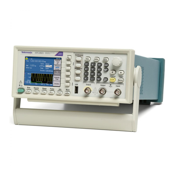
Page 27: Front Panel Overview
Arrow buttons allow you to select a specific number on the display screen when you are changing amplitude, phase, frequency, or other such values Channel On/Off and Manual Trigger buttons Trigger input connector Trigger output connector Channel output connector USB connector Function buttons Power button AFG2000 Series Service Manual... -
Page 28: Parts Of The Screen Interface
Output status: If the output is set to disable, Output Off message is displayed in this area. When you push the front panel channel output button to enable the output, the message will disappear. AFG2000 Series Service Manual... -
Page 29: Rear Panel
It can be used to input a modulated signals. Security slot: This slot allows you to use a standard laptop computer security cable to secure your instrument to your location. Fan (ventilation) vent: This is the ventilation opening for the fan. AFG2000 Series Service Manual... - Page 30 Operating basics AFG2000 Series Service Manual...
-
Page 31: Theory Of Operation
Theory of operation This section describes the electrical operation of the AFG2000 Series instruments to the module level. It describes the basic operation of each functional circuit block shown in the block diagram. (See Figure 3 on page 19.) Overview The AFG2021, AFG2021-SC, and AFG2021-BR instruments have a USB interface. -
Page 32: Main Board
Trig Out circuit. Sync Out signal from GoC ASIC is level converted to Trigger Out. ADC. Modulation by an external source is performed by digitally sampling the external input from the Ext Modulation Input connector. AFG2000 Series Service Manual... -
Page 33: Front Panel Board
This board insulates the I/O signals on the front panel BNC connectors from the chassis. Insulator board Rear BNC This board insulates the I/O signals on the rear panel BNC connectors from the chassis. Insulator board AFG2000 Series Service Manual... - Page 34 Theory of operation AFG2000 Series Service Manual...
-
Page 35: Adjustment Procedures
Generally, these adjustments should be performed every 12 months. After repair adjustments After the removal and replacement of a module due to electrical failure, perform the following two adjustments as described in this section: Reference clock Flatness AFG2000 Series Service Manual... -
Page 36: Equipment Required
012-0482-00 Tektronix part number BNC terminator , ±1 , 2 W, DC to 1 GHz, Signal termination Ω Ω 011-0049-02 Adapter dual-banana Plug BNC (female) to dual banana Tektronix part number Signal interconnection to a 103-0090-00 AFG2000 Series Service Manual... -
Page 37: Performance Conditions
The Clear CAL Data menu in the second page of Manual Calibration clears all the current adjustment parameters and sets them to 0. However, unless you push the Save/Recall menu button, the previous adjustment parameters will be recalled after a power cycle. AFG2000 Series Service Manual... -
Page 38: Frequency/Period Adjustment
1.000 Vp-p. g. Check that the Channel On/Off front panel button LED is lit. If it is not lit, then the channel output is off. Push the Channel On/Off button to turn it on. AFG2000 Series Service Manual... -
Page 39: Flatness Adjustment
Push the Amplitude/Level Menu bezel button. Push the -more- bezel button. g. Push the Units bezel button and then push the dBm bezel button to change the voltage units to dBm. AFG2000 Series Service Manual... - Page 40 The output signal frequency of the arbitrary function generator increases in 5 MHz steps every time you increase the frequency. Set the frequency of the power meter to the same frequency of the arbitrary function generator in step 4. AFG2000 Series Service Manual...
-
Page 41: Resetting The Serial Number
4. Enter the MAC address using the numeric keys and Function buttons. NOTE. Use the Function buttons to enter alphabetical characters. The Sine to More... button corresponds to A through F. Use the +/- key to enter hyphens. 5. Push the OK button. AFG2000 Series Service Manual... - Page 42 Adjustment procedures AFG2000 Series Service Manual...
-
Page 43: Maintenance
Static discharge can damage any semiconductor component in this arbitrary function generator. Minimize handling of static-sensitive modules. Transport and store static-sensitive modules in their static protected containers or on a metal rail. Label any package that contains static-sensitive modules. AFG2000 Series Service Manual... -
Page 44: Preventive Maintenance
The front and rear cases help keep dust out of the arbitrary function generator and must be in place during normal operation. To avoid damage to the arbitrary function generator, do not expose them to any sprays, liquids, or solvents. AFG2000 Series Service Manual... -
Page 45: Inspection And Cleaning
CAUTION. Avoid the use of chemical cleaning agents which might damage the plastics used in this AFG2000 Series Arbitrary Function Generators. Use only deionized water when cleaning the front panel buttons. Use an ethyl alcohol solution as a cleaner and rinse with deionized water. - Page 46 Avoid using excess force or you may damage the plastic display surface. CAUTION. To prevent getting moisture inside the arbitrary function generator during external cleaning, use only enough liquid to dampen the cloth or applicator. AFG2000 Series Service Manual...
-
Page 47: Table 3: Internal Inspection Check List
NOTE. If these steps do not remove all of the dust or dirt, please contact Tektronix for assistance. (See Contacting Tektronix at the front of this manual.) Lubrication There is no periodic lubrication required for this instrument. - Page 48 Maintenance AFG2000 Series Service Manual...
-
Page 49: Removal And Installation Procedures
Removal procedures for each of the replaceable modules. NOTE. If you are disassembling the arbitrary function generator for cleaning, refer to the inspection and cleaning instructions. (See page 33, Inspection and cleaning.) AFG2000 Series Service Manual... -
Page 50: After Repair Adjustments
16 mm (5/8 inch) deep socket with wide center hole 7 mm (9/32 inch) socket Torque wrench to 30 in-lb (3.3 N m) Screwdriver with 1/4 inch flat blade Phillips head screwdriver Pliers (all-purpose and needle-nose) Tweezers AFG2000 Series Service Manual... -
Page 51: Handle Removal/Installation
3. Grasp the handle on the other side and pull outward until the handle clears the chassis, and then slide the handle down so that the handle fits into the hole in the side of the instrument. AFG2000 Series Service Manual... -
Page 52: Case Removal/Installation
Note the orientation of the boot for reinstallation. 3. Use a screwdriver with a Torx T8 bit to remove the four screws located on the bottom of the case. Figure 7: Location of the case retaining screws AFG2000 Series Service Manual... -
Page 53: Front Panel Knob Removal/Installation
If the knob is loose or will not stay on the shaft, verify that the clip is properly seated inside the knob and that the clip is not broken. Figure 9: Location of the knob retaining clip AFG2000 Series Service Manual... -
Page 54: Front Panel Cover Removal/Installation
Note the orientation of the boot for reinstallation. 5. Remove the four retaining screws (two on each side) that attach the front cover to the chassis. Figure 10: Location of the front panel cover retaining screws AFG2000 Series Service Manual... -
Page 55: Figure 11: Removing The Front Panel Cover And Rubber Keypad
Figure 11: Removing the front panel cover and rubber keypad Installation. To install the front cover, perform the removal procedure in reverse order. Use the torque-limiting screwdriver to tighten the four front cover retaining screws to 0.49 N m. AFG2000 Series Service Manual... -
Page 56: Lcd Display And Front Panel Board Removal/Installation
The ribbon cable connects to the back of the Front Panel board using the same kind of connector. The following figure shows the connector on the back of the board in the raised (unlatched) position. Figure 12: Disconnecting the front-panel ribbon cable from the Main board AFG2000 Series Service Manual... -
Page 57: Figure 13: Removing The Front Panel Board
LCD display will detach from the Front Panel board when the four LCD display retaining screws are removed and will be connected to the board by only the ribbon cable of the LCD display. Figure 13: Removing the Front Panel board AFG2000 Series Service Manual... -
Page 58: Figure 14: Disconnecting The Lcd Display Cable
0.49 N m. The blue lines on the ribbon cable between the Front Panel board and the Main board will align with the locked connector when the cable has been properly inserted into the connector housing. AFG2000 Series Service Manual... -
Page 59: Front Bnc Insulator Board Removal/Installation
Use the torque-limiting screwdriver to tighten the two board retaining screws to 0.49 N m. Put the BNC washers on before the nuts, and then use the torque wrench to tighten the three BNC nuts to 1.38 N m. AFG2000 Series Service Manual... -
Page 60: Front Chassis And Main Chassis Separation
3. Use the torque wrench with a 16 mm (5/8 inch) deep socket with wide center hole to remove the nut and washer from each of the three BNC connectors. 4. Remove the power button by grasping the button and pulling it off of the shaft. AFG2000 Series Service Manual... -
Page 61: Figure 16: Location Of The Front Chassis Retaining Screws
0.49 N m. Put the BNC washers on before the nuts, and then use the torque wrench to tighten the three BNC nuts to 1.38 N m. Correctly orient the power button on the shaft. (See Figure 19.) AFG2000 Series Service Manual... -
Page 62: Figure 17: Correct Position Of The Emi Clip For The Usb Port
Removal and installation procedures Figure 17: Correct position of the EMI clip for the USB port Figure 18: Correct orientation of BNC insulator Figure 19: Correct orientation of power button AFG2000 Series Service Manual... -
Page 63: Power Supply Module Removal/Installation
Main board). 3. Remove the four retaining screws from the Power Supply module and lift the module out of the chassis. Figure 20: Location of the Power Supply module cables and retaining screws AFG2000 Series Service Manual... -
Page 64: Figure 21: Positioning The Power Supply Shield On The Stand-Off Posts
Be sure that the holes on the bottom of the power supply shield fit over each of the stand-off posts. (See Figure 21.) Tighten the four retaining screws on the Power Supply module to 0.88 N m. Figure 21: Positioning the power supply shield on the stand-off posts AFG2000 Series Service Manual... -
Page 65: Fan Removal/Installation
C010244 or greater, proceed to step 6. If you are servicing an AFG2021-SC or AFG2021-BR, proceed to step 6. 4. Use needle-nose pliers to lift up the edge of the rear panel label at the bottom right corner. AFG2000 Series Service Manual... -
Page 66: Figure 23: Location To Start Removing The Rear Panel Label On The Afg2021
Figure 23: Location to start removing the rear panel label on the AFG2021 5. Slowly peel back the label to minimize the glue residue left on the chassis while removing the label. Figure 24: Peeling off the rear panel label of the AFG2021 AFG2000 Series Service Manual... -
Page 67: Figure 25: Aligning The Rear Panel Label (Afg2021 With Option Gl Shown)
When you install the new rear panel label, use the two holes shown below to align the label on the rear panel. (Only applies to AFG2021 models with a serial number of C010243 or earlier.) Figure 25: Aligning the rear panel label (AFG2021 with Option GL shown) AFG2000 Series Service Manual... -
Page 68: Ac Line Filter Removal/Installation
Tighten the two AC line filter retaining screws for the fan to 0.88 N m. If you removed the earth lead to the chassis, tighten the retaining screw to 0.88 N m. Reconnect the AC line filter cables as shown below. Figure 26: AC line filter cable connections AFG2000 Series Service Manual... -
Page 69: Main Board Removal/Installation
8. Remove the two screws retaining the BNC cover plate. 9. Remove the BNC insulator from each BNC and then remove the BNC nuts and washers. 10. Remove the two screws retaining the Rear BNC Insulator board. AFG2000 Series Service Manual... -
Page 70: Figure 27: Location Of Main Board Retaining Screws And Stand-Offs
11. Remove the six screws and four stand-offs retaining the Main board to the chassis. Figure 27: Location of Main board retaining screws and stand-offs 12. Carefully slide the Main board forward until the connectors clear the rear panel and then lift the board out of the instrument. AFG2000 Series Service Manual... -
Page 71: Figure 28: Installing The Rear Bnc Washers, Nuts, And Insulators
Tighten the six Main board retaining screws to 0.88 N m; tighten the four Main board stand-offs for the Power Supply module to 0.49 N m. Figure 28: Installing the rear BNC washers, nuts, and insulators AFG2000 Series Service Manual... - Page 72 Removal and installation procedures AFG2000 Series Service Manual...
-
Page 73: Troubleshooting
Troubleshooting This section contains the following information to help you isolate faulty modules in a AFG2000 Series Arbitrary Function Generator. Troubleshooting trees – Show how to find and isolate faulty modules. Diagnostics – Describes the diagnostics supplied with the arbitrary function generator, its operation, and status messages. -
Page 74: Figure 29: Troubleshooting Tree
Troubleshooting Figure 29: Troubleshooting tree AFG2000 Series Service Manual... -
Page 75: Diagnostics
If the diagnostic completes without finding any problems, the message “PASSED” is displayed. When an error is detected during diagnostic execution, the instrument shows an error code. (See page 65, Diagnostic error codes.) 4. Press any front panel button to exit from the diagnostics test. AFG2000 Series Service Manual... - Page 76 If the diagnostic completes without finding any problems, the message “PASSED” is displayed. When an error is detected during diagnostic execution, the instrument shows an error code. (See page 65, Diagnostic error codes.) 4. Press any front panel button to exit from the calibration test. AFG2000 Series Service Manual...
-
Page 77: Table 5: Error Codes
Output gain failure 2401 x3dB attenuator failure 2403 x6dB attenuator failure 2405 x10dB attenuator failure 2407 x20dB 1 attenuator failure 2409 x20dB 2 attenuator failure 2411 Filter failure 2413 x20dB 3 attenuator failure 2501 Sine Flatness failure AFG2000 Series Service Manual... - Page 78 Troubleshooting AFG2000 Series Service Manual...
-
Page 79: Diagrams
Diagrams The diagram in this section shows how the modules in the generator connect together. Figure 30: Interconnections for the AFG2021 (GPIB and LAN only on AFG2021 with Option GL) AFG2000 Series Service Manual... - Page 80 Diagrams AFG2000 Series Service Manual...
-
Page 81: Replaceable Parts
This section contains a list of the replaceable modules for the arbitrary function generators. Use this list to identify and order replacement parts. Parts ordering information Replacement parts are available through your local Tektronix field office or representative. Changes to Tektronix instruments are sometimes made to accommodate improved components as they become available and to give you the benefit of the latest... -
Page 82: Using The Replaceable Parts List
Figure & index number Items in this section are referenced by component number. Tektronix part number Use this part number when ordering replacement parts from Tektronix. Instrument model This indicates the model of instrument that uses this item. 4 and 5 Serial number Column four indicates the serial number at which the part was first effective. -
Page 83: Table 7: Front Panel Assembly Replaceable Parts (See Figure 31.)
NUT, PLAIN, HEX; 0.5-28 X 0.625 HEX, BRS, NKL PL 210-1544-XX WASHER, SPRING; 0.610 OD X 0.490 ID X 0.007 THK, WAVE SHAPE, STAINLESS STEEL 878-0575-XX CIRCUIT BOARD ASSY; FRONT BNC INSULATOR; 389442300; UNTESTED 878-0585-XX CIRCUIT BOARD ASSY; FRONT PANEL (4 LAYERS); 389446100; UNTESTED AFG2000 Series Service Manual... -
Page 84: Figure 31: Front Panel Assembly Exploded Diagram
Replaceable parts Figure 31: Front panel assembly exploded diagram AFG2000 Series Service Manual... -
Page 85: Table 8: Chassis Assembly Replaceable Parts (See Figure 32.)
PWR INSULATOR (PROTECTION COVER) 119-7271-03 POWER SUPPLY; AC-DC; 150 W MAX IN; 87-264 VAC 47-63 HZ, 100-127 VAC 360-440 HZ IN; +4.3V @ 2.3A, +7.5V @ 3.2A, +18V @ 2A, -18V @ 2A OUT; SAFETY CONTROLLED AFG2000 Series Service Manual... - Page 86 WASHER, SPRING; 0.610 OD X 0.490 ID X 0.007 THK, WAVE SHAPE, STAINLESS STEEL 220-0265-00 NUT, PLAIN, HEX; 0.5-28 X 0.625 HEX, BRS, NKL PL 386-7634-00 BNC COVER 131-6363-00 EMI GASKET; GROUNDING, 0.320 L X 0.365 W (2 CONTACTS) X 0.110 DEEP, ELECTROLESS NICKEL PLATE AFG2000 Series Service Manual...
-
Page 87: Figure 32: Chassis Assembly Exploded Diagram
Replaceable parts Figure 32: Chassis assembly exploded diagram AFG2000 Series Service Manual...
Need help?
Do you have a question about the AFG2000 and is the answer not in the manual?
Questions and answers