
Related Manuals for Tektronix AFG3000C Series


Summary of Contents for Tektronix AFG3000C Series
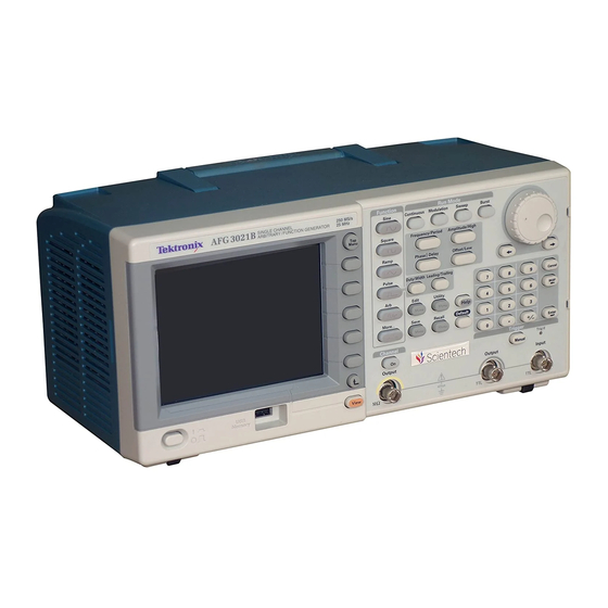
- Page 1 AFG3000C and AFG3000 Series Arbitrary Function Generators Specifications and Performance Verification Technical Reference www.tek.com *P077069103* 077-0691-0 3...
- Page 2 Copyright © Tektronix. All rights reserved. Licensed software products are owned by Tektronix or its subsidiaries or suppliers, and are protected by national copyright laws and international treaty provisions. Tektronix products are covered by U.S. and foreign patents, issued and pending. Information in this publication supersedes that in all previously published material.
-
Page 3: Table Of Contents
Table of Contents General safety summary ..................Service safety summary................... Preface ....................... Finding other information..................Manual conventions ................... Specifications ....................... Electrical specifications ..................Input and output specifications ................General specifications ..................Performance verification ..................Self tests ....................... Error codes ....................Performance tests ..................... - Page 4 Table of Contents List of Figures Figure 1: AFG3000 Series dimensions ................. Figure 2: RM3100 Rackmount dimensions ..............Figure 3: Frequency/period test.................. Figure 4: 50 Ω terminator accuracy ................Figure 5: Amplitude test ..................Figure 6: 50 Ω terminator accuracy ................Figure 7: DC offset tests ..................
- Page 5 Table of Contents List of Tables Table 1: Supported products..................Table 2: Operating mode ..................Table 3: Waveforms ....................Table 4: (Category) specifications ................Table 5: Phase (except DC, Noise, and Pulse) ..............Table 6: Lead delay (pulse)..................Table 7: Amplitude ....................Table 8: DC offset ....................
-
Page 6: General Safety Summary
General safety summary General safety summary Review the following safety precautions to avoid injury and prevent damage to this product or any products connected to it. To avoid potential hazards, use this product only as specified. Only qualified personnel should perform service procedures. While using this product, you may need to access other parts of a larger system. - Page 7 General safety summary Terms in this manual These terms may appear in this manual: WARNING. Warning statements identify conditions or practices that could result in injury or loss of life. CAUTION. Caution statements identify conditions or practices that could result in damage to this product or other property.
- Page 8 General safety summary AFG3000C and AFG3000 Series Specifications and Performance Verification...
-
Page 9: Service Safety Summary
Service safety summary Only qualified personnel should perform service procedures. Read this Service Safety Summary and the General Safety Summary before performing any service procedures. Do Not Service Alone. Do not perform internal service or adjustments of this product unless another person capable of rendering first aid and resuscitation is present. - Page 10 Service Safety Summary AFG3000C and AFG3000 Series Specifications and Performance Verification...
-
Page 11: Preface
Preface This manual provides instructions to verify the performance of the AFG3000C and AFG3000 Series Arbitrary Function Generators to the module level. Unless noted otherwise, the term “AFG3000 Series” refers to the models in the following table. Table 1: Supported products AFG3011 AFG3021B AFG3011C... -
Page 12: Finding Other Information
Preface Finding other information This manual focuses on the performance verification of the instrument. See the following list for other documents supporting the instrument on www.tek.com. Document Description AFG3000C and AFG3000 Series A quick reference to major features of the instrument and how they operate. It also provides Quick Start User Manual several tutorials to familiarize you with basic instrument features. -
Page 13: Specifications
Specifications These specifications apply to all AFG3000C and AFG3000 Series Arbitrary Function Generators, unless otherwise stated. All specifications are guaranteed unless labeled “typical”. Typical specifications are provided for your convenience but are not guaranteed. Specifications that are check marked with the symbol are checked directly (or indirectly) in the Performance Verification section. -
Page 14: Table 3: Waveforms
Specifications Table 3: Waveforms Characteristic Description Standard Sine, Square, Pulse, Ramp, More (Sin(x)/x, Noise, DC, Gaussian, Lorentz, Exponential Rise, Exponential Decay, and Haversine) Arbitrary waveform 2 to 131,072 Waveform length Sampling rate AFG3021B / 3022B / 250 MS/s 3021C / 3022C / 3011/ 3011C AFG3101 / 3101C / 3102 250 MS/s or 1 GS/s (rate changes automatically at ≤16K) - Page 15 Specifications Table 4: (Category) specifications (cont.) PV reference Characteristic Description page AFG3251 / 3251C / 3252 1 μHz to 120 MHz / 3252C Pulse AFG3011 / 3011C 1 mHz to 5 MHz AFG3021B / 3022B 1 mHz to 12.5 MHz AFG3021C / 3022C 1 mHz to 25 MHz AFG3051C / 3052C...
- Page 16 Specifications AFG3000C and AFG3000 Series Specifications and Performance Verification...
-
Page 17: Table 5: Phase (Except Dc, Noise, And Pulse)
Specifications Table 4: (Category) specifications (cont.) PV reference Characteristic Description page Resolution 1 μHz or 12 digits ±1 ppm, 0 °C to 50 °C (except Arb) (See page 51, Accuracy stability Frequency/period ±1 ppm ±1 mHz, 0 °C to 50 °C (Arb) test.) Accuracy aging ±1 ppm/year... -
Page 18: Table 8: Dc Offset
Specifications Table 7: Amplitude (cont.) PV reference Characteristic Description page AFG3251 / 3252 / 3251C / 50 mV to 5 V 100 mV to 10 V (into open circuit load) 3252C (See page 52, Accuracy Amplitude test.) AFG3011 / 3011C ±(2% of setting +2 mV) (at 1 kHz sine waveform amplitude >... -
Page 19: Table 9: Internal Noise Add
Specifications Table 9: Internal noise add Characteristic Description Range 0% to 50% of amplitude setting Resolution Table 10: Output characteristics PV reference Characteristic Description page Sine wave (See page 56, Flatness (at 1.0 V amplitude (+4 dBm), relative to 1 kHz) AC Flatness test.) AFG3011 / 3011C... - Page 20 Specifications Table 10: Output characteristics (cont.) PV reference Characteristic Description page AFG3051C / 3052C 10 Hz ≤ frq < 20 kHz: < –70 dBc 20 kHz ≤ frq < 1 MHz: < –60 dBc 1 MHz ≤ frq < 5 MHz: < –50 dBc 5 MHz ≤...
- Page 21 Specifications Table 10: Output characteristics (cont.) PV reference Characteristic Description page AFG3011 / 3011C / –63 dBm 3021B / 3021C / 3022B / 3022C / 3051C / 3052C AFG3101 / 3101C / 3102 –57 dBm / 3102C / 3151C / 3152C / 3251C / 3251C / 3252 / 3252C Square wave...
- Page 22 Specifications Table 10: Output characteristics (cont.) PV reference Characteristic Description page AFG3251 / 3251C / 3252 4 ns to 999.99 s / 3252C Resolution 10 ps or 5 digits Pulse duty 0.001% to 99.999% Leading edge/trailing edge transition time (at 10% to 90% of amplitude, respectively) AFG3011 / 3011C 50 ns to 0.625 * pulse period AFG3021B / 3022B...
-
Page 23: Table 11: Modulation
Specifications Table 10: Output characteristics (cont.) PV reference Characteristic Description page AFG3021B / 3021C / ≤ 14 ns 3022B / 3022C AFG3051C / 3052C ≤ 10 ns AFG3101 / 3101C / 3102 ≤ 8 ns / 3102C ≤ 5 ns AFG3151C / 3152C AFG3251 / 3251C / 3252 ≤... - Page 24 Specifications Table 11: Modulation (cont.) Characteristic Description AFG3021B / 3021C / DC to 12.5 MHz 3022B / 3022C AFG3051C / 3052C DC to 25 MHz AFG3101 / 3101C / 3102 DC to 50 MHz / 3102C AFG3151C / 3152C DC to 75 MHz AFG3251 / 3251C / 3252 DC to 120 MHz / 3252C...
- Page 25 Specifications Table 11: Modulation (cont.) Characteristic Description AFG3251 / 3251C / 3252 1 μHz to 240 MHz / 3252C Start/stop frequency (Arb) AFG3011 / 3011C 1 mHz to 5 MHz AFG3021B / 3021C / 1 mHz to 12.5 MHz 3022B / 3022C AFG3051C / 3052C 1 mHz to 25 MHz AFG3101 / 3101C / 3102...
-
Page 26: Input And Output Specifications
Specifications Input and output specifications Table 12: Front panel Characteristic Description Trigger output Level Positive TTL level pulse into 1 kΩ Impedance 50 Ω Jitter (rms), typical AFG3011 / 3011C / 500 ps 3021B / 3021C / 3022B / 3022C AFG3051C / 3052C 300 ps AFG3101 / 3101C / 3102... -
Page 27: General Specifications
Specifications Table 13: Rear panel (cont.) Characteristic Description Impedance 50 Ω Input range -1 V to +1 V (DC + peak AC) Bandwidth DC to 10 MHz (-3 dB) at 1 Vp-p General specifications Table 14: Power Characteristic Description Source voltage and frequency 100 V to 240 V, 47 Hz to 63 Hz 115 V, 360 to 440 Hz Power consumption... - Page 28 Specifications Table 16: System characteristics (cont.) Characteristic Description Amplitude change 90 ms 97 ms 90 ms 48 ms 50 ms 49 ms Select user Arbitrary waveform is 4K points (USB memory) Select user Arbitrary 260 ms 266 ms 240 ms waveform is 128K points (USB memory) Data download, typical...
-
Page 29: Figure 1: Afg3000 Series Dimensions
Specifications Figure 1: AFG3000 Series dimensions Figure 2: RM3100 Rackmount dimensions AFG3000C and AFG3000 Series Specifications and Performance Verification... - Page 30 Specifications AFG3000C and AFG3000 Series Specifications and Performance Verification...
-
Page 31: Performance Verification
Performance verification Two types of Performance Verification procedures can be performed on this product: Self Tests and Performance Tests. You may not need to perform all of these procedures, depending on what you want to accomplish. To quickly confirm that the AFG3000 Series Arbitrary Function Generators are operating properly, complete the Self Tests. - Page 32 Performance verification 1. Select Diagnostics in the Utility menu: Utility (front-panel) > -more- (bezel) > Diagnostics/Calibration > Execute Diagnostics 2. Wait until the test is completed. 3. Verify passing of the diagnostics. If the diagnostics completes without finding any problems, the message “PASSED”...
-
Page 33: Error Codes
Performance verification Error codes If Diagnostics detects a malfunction, it displays the character string “Fail” and the error code. Table 17 describes the Error code and related modules Category of the Diagnostics Error Code. Table 17 shows the error code and related modules reporting a failure. Table 17: Error codes Error code Description... - Page 34 Performance verification Table 17: Error codes (cont.) Error code Description Related module 2102 Calibration data invalid 2201 ASIC1 memory failure A1x/A3x/A4x 2202 ASIC2 memory failure A12/A32/A42 2203 ASIC1 Overheat A1x/A3x/A4x 2204 ASIC2 Overheat A12/A32/A42 — Output Diagnostics Error Codes — 2301 CH1 Internal offset failure A1x/A3x/A4x...
-
Page 35: Performance Tests
Performance verification Performance tests The Performance Tests include functional tests, such as the interface functional test, in this manual. The Functional Tests verify the functions; they verify that the AFG3000 Series Arbitrary Function Generators features operate. They do not verify that they operate within limits. - Page 36 Performance verification AFG3000C and AFG3000 Series Specifications and Performance Verification...
-
Page 37: Test Record
R&S NRV-Z5 Measures voltage. Used in to 100 mW (-30 dBm to multiple procedures. +20 dBm) Accuracy: 5 × 10 Tektronix FCA3000 opt HS Frequency Counter Checks clock frequency. Oscilloscope 1 GHz Bandwidth 50 Ω input Tektronix TDS5104B Checks output signals. Used termination in multiple procedures. -
Page 38: Table 20: Afg3000 Series Performance Test Record
Performance verification Table 20: AFG3000 Series Performance Test Record Instrument Serial Number: Certificate Number: Temperature: RH %: Date of Calibration: Technician: Frequency, Amplitude, DC Offset, and AC Flatness Test Record Minimum Test result Maximum Frequency Sine at 1.000000 MHz 0.999998 MHz* 1.000002 MHz* Pulse at 1.000000 MHz 0.999998 MHz*... - Page 39 Performance verification AFG3000C and AFG3000 Series Specifications and Performance Verification...
- Page 40 Performance verification Frequency, Amplitude, DC Offset, and AC Flatness Test Record (cont.) Amplitude (AFG325x / 325xC) CF = 2 / (1 + 50 Ω / Measurement Ω) = CH1 Amplitude Minimum Test result Maximum 0.030 Vrms at 1.00 kHz (30.0 × CF - 0.654) mVrms (30.0 ×...
- Page 41 Performance verification AFG3000C and AFG3000 Series Specifications and Performance Verification...
- Page 42 Performance verification Frequency, Amplitude, DC Offset, and AC Flatness Test Record (cont.) AC Flatness (AFG3011 / 3011C) CH1 AC Flatness Minimum Test result Maximum ———- ———- Frequency 1.00 kHz dB ( = Reference) (Ampl: +4.0 dBm) Frequency 500 kHz Reference - 0.15 dB Reference + 0.15 dB Frequency 1.00 MHz Reference - 0.15 dB...
- Page 43 Performance verification Frequency, Amplitude, DC Offset, and AC Flatness Test Record (cont.) CH2 AC Flatness ———- ———- Frequency 1.00 kHz dB ( = Reference) (Ampl: +4.0 dBm) Frequency 500 kHz Reference - 0.15 dB Reference + 0.15 dB Frequency 1.00 MHz Reference - 0.15 dB Reference + 0.15 dB Frequency 5.00 MHz...
- Page 44 Performance verification Frequency, Amplitude, DC Offset, and AC Flatness Test Record (cont.) AC Flatness (AFG310x / 310xC / 315xC) CH1 AC Flatness Minimum Test result Maximum ———- ———- Frequency 1.00 kHz dB ( = Reference) (Ampl: +4.0 dBm) Frequency 1.00 MHz Reference - 0.15 dB Reference + 0.15 dB Frequency 5.00 MHz...
- Page 45 Performance verification Frequency, Amplitude, DC Offset, and AC Flatness Test Record (cont.) Frequency 50.00 MHz Reference - 0.50 dB Reference + 0.50 dB Frequency 100.0 MHz Reference - 1.00 dB Reference + 1.00 dB Frequency 150.00 MHz Reference - 1.00 dB Reference + 1.00 dB Frequency 240.0 MHz Reference - 2.00 dB...
- Page 46 Performance verification Harmonic Distortion Test Record (cont.) Harmonic Distortion Fundamental (amplitude 1 V = reference Limit CH2 Harmonic Distortion (dBc) reading - 0 dBc Nth - reference < reference -60 dBc (dBc) Sine 100 kHz 100 kHz 200 kHz 300 kHz 400 kHz 500 kHz CH1 Harmonic...
- Page 47 Performance verification Harmonic Distortion Test Record (cont.) Harmonic Distortion Fundamental (amplitude 1 V = reference Limit CH1 Harmonic Distortion (dBc) reading - 0 dBc Nth - reference < reference -60 dBc (dBc) CH2 Harmonic Distortion (dBc) reading - 0 dBc Nth - reference <...
- Page 48 Performance verification Harmonic Distortion Test Record (cont.) Harmonic Distortion Fundamental (amplitude 1 V = reference Limit reading - 0 dBc Nth - reference < reference -40 dBc (dBc) 25 MHz 50 MHz 75 MHz 100 MHz 125 MHz Sine 25 MHz CH1 Harmonic Distortion (dBc) reading -...
- Page 49 Performance verification Harmonic Distortion Test Record (cont.) Harmonic Distortion Fundamental (amplitude 1 V = reference Limit reading - 0 dBc Nth - reference < reference -37 dBc (dBc) CH2 Harmonic Distortion (dBc) reading - 0 dBc Nth - reference < reference -37 dBc (dBc)
- Page 50 Performance verification Harmonic Distortion Test Record (cont.) Harmonic Distortion Fundamental (amplitude 1 V = reference Limit AFG325x Spectrum Analyzer reading Sine 1 MHz 1 MHz 2 MHz 3 MHz 4 MHz 5 MHz CH1 Harmonic Distortion (dBc) reading - 0 dBc Nth - reference <...
- Page 51 Performance verification Harmonic Distortion Test Record (cont.) Harmonic Distortion Fundamental (amplitude 1 V = reference Limit CH2 Harmonic Distortion (dBc) reading - 0 dBc Nth - reference < reference -30 dBc (dBc) AFG3000C and AFG3000 Series Specifications and Performance Verification...
- Page 52 Performance verification Total Harmonic Distortion (THD) Test Record AFG3xxxx Spectrum Analyzer reading Fundamental reference Sine 20.0 kHz 20 kHz 40 kHz 60 kHz 80 kHz 100 kHz 120 kHz 140 kHz CH1 reading (dBm) reading - reference (A (dBc) = 10 Bn/20 Limit <...
- Page 53 Performance verification Spurious Test Record (AFG3011 / 3011C) Spectrum Analyzer Measurement Frequency Center Span Spurious Spurious Limit Frequency Frequency (Max) CH1 Spurious Sine 100 kHz 10 MHz / 20 MHz / 20 kHz / < -60 dBc 300 MHz 600 MHz 20 kHz Sine 1.00 MHz 10 MHz /...
- Page 54 Performance verification Spurious Test Record (AFG305xC) Spectrum Analyzer Measurement Frequency Center Span Spurious Spurious Limit Frequency Frequency (Max) CH1 Spurious Sine 100 kHz 10 MHz 20 MHz 20 kHz < -60 dBc 300 MHz 600 MHz 20 kHz Sine 1.00 MHz 10 MHz 20 MHz 20 kHz...
- Page 55 Performance verification Spurious Test Record (AFG310x / 310xC) Spectrum Analyzer Measurement Frequency Center Span Spurious Spurious Limit Frequency Frequency (Max) CH1 Spurious Sine 100 kHz 10 MHz 20 MHz 20 kHz < -60 dBc 300 MHz 600 MHz 20 kHz Sine 1.00 MHz 10 MHz 20 MHz...
- Page 56 Performance verification Spurious Test Record (AFG325x / 325xC) CH1 Spurious Sine 100 kHz 10 MHz 20 MHz 20 kHz 20 kHz < -50 dBc 300 MHz 600 MHz Sine 1.00 MHz 10 MHz 20 MHz 20 kHz < -47 dBc 300 MHz 600 MHz 20 kHz...
- Page 57 Performance verification Rise/Fall Time Test Record (cont.) - - - - - Fall Time Amplitude: 10.0 Vpp 50 ns AFG302xB - - - - - Rise Time Amplitude: 1.0 Vpp 18 ns - - - - - Fall Time Amplitude: 1.0 Vpp 18 ns - - - - - Rise Time Amplitude: 10.0 Vpp...
- Page 58 Performance verification Rise/Fall Time Test Record (cont.) - - - - - Rise Time Amplitude: 10.0 Vpp 5 ns - - - - - Fall Time Amplitude: 10.0 Vpp 5 ns - - - - - Rise Time Amplitude: 1.0 Vpp 5 ns - - - - - 5 ns...
-
Page 59: Frequency/Period Test
Performance verification Frequency/period test This test verifies the frequency accuracy of the arbitrary function generator. All output frequencies are derived from a single generated frequency. Only one frequency point of channel 1 is required to be checked. 1. Connect the arbitrary function generator to the frequency counter as shown in the following figure. -
Page 60: Amplitude Test
Performance verification Amplitude test This test verifies the amplitude accuracy of the arbitrary function generator. All output amplitudes are derived from a combination of attenuators and 3 dB variable gain. Some amplitude points are checked. This test uses a 50 Ω terminator. It is necessary to know the accuracy of the 50 Ω... - Page 61 Performance verification 4. Set up the arbitrary function generator using the following steps: Select menu Setting Operation Function Sine Sine (front) Frequency 1.000000 kHz Frequency/Period (front) Amplitude Units Vrms The voltage unit should Top Menu > Amplitude/Level Menu > be matched to that of DMM. -more- >...
-
Page 62: Dc Offset Test
Performance verification DC Offset test This test verifies the DC offset accuracy of the arbitrary function generator. This test uses a 50 Ω terminator. It is necessary to know the accuracy of a 50 Ω terminator in advance of this test. This accuracy is used for as a calibration factor. 1. - Page 63 Performance verification 4. Set up the arbitrary function generator using the following steps: Select menu Setting Operation Function More... (front) > More Waveform Menu > DC Offset + 5.000 V + 2.500 V Offset/Low (front) (AFG325x) Channel 1 Output On (front) 5.
-
Page 64: Ac Flatness Test
Performance verification AC Flatness test This test verifies the flatness of a sine wave to the 1 kHz reference waveform. 1 kHz test setup 1. Connect a 50 Ω terminator to the DMM as shown in the following figure and measure the resistance value. -
Page 65: Figure 10: >1 Khz Setup For Ac Flatness Test
Performance verification >100 kHz test setup 1. Connect the arbitrary function generator to the power meter with a power head as shown in the following figure. Figure 10: >1 kHz setup for AC Flatness test 2. Set up the arbitrary function generator using the following steps: Select menu Setting Operation... - Page 66 Performance verification AFG302xB / 302xC Measurement Range Sine + 4.0 dBm 500.00 kHz Reference ± 0.15 Sine + 4.0 dBm 1.00 MHz Reference ± 0.15 Sine + 4.0 dBm 5.00 MHz Reference ± 0.30 Sine + 4.0 dBm 15.00 MHz Reference ±...
-
Page 67: Harmonics Distortion Test
Performance verification AFG325x / 325xC Measurement Range Sine + 4.0 dBm 5.00 MHz Reference ± 0.30 Sine + 4.0 dBm 25.00 MHz Reference ± 0.50 Sine + 4.0 dBm 50.00 MHz Reference ± 0.50 Sine + 4.0 dBm 100.00 MHz Reference ±... - Page 68 Performance verification 4. Set up the spectrum analyzer according the frequency setup of the arbitrary function generator. 5. Set the Ref Level of the spectrum analyzer to 8 dBm. 6. Read the signal level in the Fundamental frequency for each signal. Use this level as a Reference value in step 7.
- Page 69 Performance verification AFG310x / 310xC Spectrum Analyzer Measurement Limit Frequency Fundamental Nth - Center Span Frequency Reference Reference) 1 MHz 5.00 MHz 10 MHz 20 kHz 1 MHz 2 MHz 3 MHz 4 MHz 5 MHz < -50 dBc 5 MHz 20 MHz 5 MHz 10 MHz...
-
Page 70: Total Harmonic Distortion Test
Performance verification Total Harmonic Distortion test This test verifies the total harmonic distortion (THD) using a spectrum analyzer. 1. Connect the arbitrary function generator to the spectrum analyzer as shown in the following figure. Figure 12: Total Harmonic distortion tests 2. - Page 71 Performance verification 7. Calculate each B1 to B7, C1 to C7 value and the THD using the following table. NOTE. When all the harmonic components are -62 dBm or less, the calculation of THD can be skipped because it is THD < 0.2%. 8.
-
Page 72: Spurious Test
Performance verification Spurious test This test verifies the spurious frequency signal using a spectrum analyzer. 1. Connect the arbitrary function generator to the spectrum analyzer as shown in the following figure. Figure 13: Spurious tests 2. Set up the arbitrary function generator using the following steps: Select menu Setting Operation... - Page 73 Performance verification AFG3011 / 3011C Spectrum analyzer Measurement Frequency Limit Center Span Spurious Spurious Frequency Frequency (Max) 100.00 kHz 10 MHz 20 MHz 20 kHz < -60 dBc 300 MHz 600 MHz 20 kHz 1.00 MHz 10 MHz 20 MHz 20 kHz <...
- Page 74 Performance verification AFG310x / 310xC Spectrum analyzer Measurement 1.00 MHz 10 MHz 20 MHz 20 kHz < -50 dBc 300 MHz 600 MHz 20 kHz 10.00 MHz 10 MHz 20 MHz 20 kHz < -50 dBc 300 MHz 600 MHz 20 kHz 25.00 MHz 10 MHz...
-
Page 75: Rise-Fall Time Test
Performance verification AFG325x / 325xC Spectrum analyzer Measurement 50.00 MHz 10 MHz 20 MHz 20 kHz < -41 dBc 300 MHz 600 MHz 20 kHz 100.00 MHz 10 MHz 20 MHz 20 kHz < -35 dBc 300 MHz 600 MHz 20 kHz 200.00 MHz 10 MHz... - Page 76 Performance verification Select menu Setting Operation Offset 0.0 V TopMenu > Offset/Low (front) Channel 1 Output On (front) 3. Set up the Oscilloscope so the square waveform of 5 division amplitude is displayed. 4. Verify that the rise/fall time of the square waveform on the oscilloscope at each amplitude is equal to or less than the limit specified in the following tables.
- Page 77 Performance verification AFG310x / 310xC Oscilloscope Measurement Function Frequency Offset Amplitude Vertical Horizontal Limit Square 10.00 MHz 0.0 V 1.0 Vpp 200 mV/div 2 ns/div ≤ 5 ns ≤ 5 ns Square 10.00 MHz 0.0 V 10.0 Vpp 200 mV/div 2 ns/div with x10 attenuator...
Need help?
Do you have a question about the AFG3000C Series and is the answer not in the manual?
Questions and answers