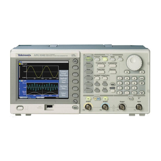
Tektronix AFG3011 User Manual
Arbitrary function generator afg3000 series; afg3000c series;
Hide thumbs
Also See for AFG3011:
- Technical reference (77 pages) ,
- Programmer's manual (232 pages) ,
- Quick start user manual (108 pages)

Related Manuals for Tektronix AFG3011


Summary of Contents for Tektronix AFG3011
- Page 1 Test Equipment Depot - 800.517.8431 - 99 Washington Street Melrose, MA 02176 - TestEquipmentDepot.com AFG3000 and AFG3000C Series Arbitrary Function Generators User Manual *P077095701* 077-0957-01...
- Page 3 AFG3000 and AFG3000C Series Arbitrary Function Generators User Manual...
- Page 4 Copyright © Tektronix. All rights reserved. Licensed software products are owned by Tektronix or its subsidiaries or suppliers, and are protected by national copyright laws and international treaty provisions. Tektronix products are covered by U.S. and foreign patents, issued and pending. Information in this publication supersedes that in all previously published material.
- Page 5 Warranty Tektronix warrants that the product will be free from defects in materials and workmanship for a period of three (3) years from the date of original purchase from an authorized Tektronix distributor. If the product proves defective during this warranty period, Tektronix, at its option, either will repair the defective product without charge for parts and labor, or will provide a replacement in exchange for the defective product.
-
Page 7: Table Of Contents
Protect your DUT ..................... Update your instrument firmware ................Connect to a network ..................Equivalent Output Circuits .................. Overheat Protection (AFG3011 / 3011C Only)............Instrument interface, front panel, and rear panel ............... Front panel overview ..................Parts of the screen interface ................. - Page 8 Table of Contents Generate a Pulse Waveform ................. Save/Recall Arbitrary Waveforms ................Generate an Arbitrary Waveform ................Modify an Arbitrary Waveform (Edit Menu) .............. Generate Noise/DC ................... Generate a Burst Waveform ................. Sweep a Waveform ................... Modulate a Waveform..................Trigger Out ....................Adjusting Parameters of Two Channel Signals (dual-channel models only)......
-
Page 9: List Of Figures
List of Figures Figure 1: Fuse and fuse adapter.................. AFG3000 and AFG3000C Series User Manual... - Page 10 Table of Contents List of Tables Table i: Supported products ..................Table 1: General features for regular and B models ............Table 2: General features for AFG30xxC models .............. Table 3: General features for AFG31xxC and AFG32xxC models ........... Table 4: Standard accessories ..................Table 5: Optional accessories ..................
-
Page 11: Environmental Considerations
Union requirements according to Directives 2002/96/EC and 2006/66/EC on waste electrical and electronic equipment (WEEE) and batteries. For information about recycling options, check the Support/Service section of the Tektronix Web site. Restriction of Hazardous This product is classified as Monitoring and Control equipment, and is outside the scope of the 2002/95/EC RoHS Directive. - Page 12 Environmental Considerations AFG3000 and AFG3000C Series User Manual...
-
Page 13: Preface
AFG3151C AFG3152C AFG3251C AFG3252C Where to find more information The following table lists related documentation available for your instrument. The documentation is available on the Document CD and on the Tektronix Web site. Item Purpose Location Safety and Safety, compliance,... -
Page 14: Conventions Used In This Manual
Preface Item Purpose Location Service Manual Self-service and Performance test Technical Specifications Reference and performance verification procedures ArbExpress Waveform creation Software CD Import waveforms from oscilloscope or NOTE. Please see the printed Safety and Compliance Instructions that were shipped with your instrument for general safety summary, EMC compliance, and safety compliance information. -
Page 15: Getting Started
The following tables describe some of the general features of your instrument. An “X” means the feature is included with the model. Table 1: General features for regular and B models AFG3021B/ Feature AFG3011 AFG3022B AFG3101/ AFG3102 AFG3251/ AFG3252 Channel... -
Page 16: Table 2: General Features For Afg30Xxc Models
Getting started Table 2: General features for AFG30xxC models Feature AFG3011C AFG3021C/ AFG3022C AFG3051C/ AFG3052C Channel 1 / 2 1 / 2 Sine 10 MHz 25 MHz 50 MHz Pulse 5 MHz 25 MHz 40 MHz Memory 2 to 131,072 2 to 131,072 2 to 131,072 >16,384 to... -
Page 17: Table 3: General Features For Afg31Xxc And Afg32Xxc Models
Getting started Table 3: General features for AFG31xxC and AFG32xxC models Feature AFG3101C / AFG3102C AFG3151C/ AFG3152C AFG3251C / AFG3252C Channel 1 / 2 1 / 2 1 / 2 Sine 100 MHz 150 MHz 240 MHz Pulse 50 MHz 100 M 120 MHz Memory... -
Page 18: Before Installation
Getting started Before Installation Inspect the instrument carton for external damage. If the carton is damaged, notify the carrier. Remove the instrument from its package and check that it has not been damaged in transit. Verify that the carton contains the instrument and its standard accessories. Operating Requirements Environmental Place the instrument on a cart or bench, observing... -
Page 19: Standard Accessories
Getting started Standard Accessories Unpack the instrument and check that you received all items listed as Standard Accessories. Check the Tektronix Web site for the most current information. Table 4: Standard accessories Description Tektronix part number AFG3000 Series Arbitrary Function Generators Safety and Compliance Instructions... -
Page 20: Optional Accessories
Getting started Table 4: Standard accessories (cont.) Description Tektronix part number - - - No power cord or AC adapter (Option A99) 012-1732-XX 50 Ω BNC cable, double-shielded, 91 cm (36 in) These manuals contain a language overlay for the front panel controls. -
Page 21: Power The Instrument On And Off
Getting started Power the instrument on and off The following procedures show you how to apply power to the instrument and turn it on and off. Power on Insert the AC power cord into the power receptacle on the rear panel. Push the front-panel power button to power on the instrument. -
Page 22: Change Instrument Settings At Power-On
Getting started Change instrument settings at power-on The default settings are restored when you power on the instrument. You can change the power-on settings to the last powered-off settings from the Utility menu using the following procedure. NOTE. You can restore the instrument to its default settings at any time by pushing the front-panel Default button. -
Page 23: Erase Instrument Setups And Waveforms From Memory
Getting started Erase instrument setups and waveforms from memory You can also erase all instrument setups and waveforms from the instrument internal memory using the following procedure. NOTE. You can restore the instrument to its default settings at any time without erasing memory by pushing the front-panel Default button. - Page 24 Getting started Push the front-panel Utility button. Push the -more- bezel button. Push the Diagnostics/Calibration bezel button. To execute the instrument diagnostics, push the Execute Diagnostics bezel button. To execute self calibration, push the Execute Calibration bezel button. If Diagnostics completes without any errors, the message “PASSED”...
-
Page 25: Select A Local Language
Getting started Select a local language You can select the language you want displayed on the instrument screen. Push the front-panel Utility button. Push the Language bezel button. Select the desired language. You can select from English, French, German, Japanese, Korean, Simple Chinese, Traditional Chinese, and Russian. -
Page 26: Protect Your Instrument From Misuse
Getting started Protect your instrument from misuse Check input and output Locate the output connectors connectors on the front panel. The image shown here shows the outputs. Locate the input connector on the front panel. Some instrument models have more than one input. - Page 27 Getting started Use fuse adapter The instrument will be damaged if a large DC or AC voltage is applied to the output or input connectors. To protect the output circuits, a fuse adapter is provided as an optional accessory. When the instrument is used by students or other inexperienced users, always attach the fuse adapter to the output connectors to avoid damage.
-
Page 28: Floating Ground
If the fuse opens, you need to contact your local Tektronix Service Support. When a potential voltage exists between the common ground and chassis ground, short-circuiting between them may lead to excessive current flow and the internal... -
Page 29: Protect Your Dut
Getting started Protect your DUT Use care when you connect the instrument Channel Output to your DUT (device under test). To avoid damage to your DUT, the following preventive measures are provided. Follow these steps to set the limit values for high level and low level. Push the front-panel Top Menu button. -
Page 30: Update Your Instrument Firmware
Version information is displayed on the screen. Confirm the firmware version of your instrument. Ceck if Tektronix offers a newer firmware version. Download the compressed zip file with the most current firmware to your Unzip the downloaded file and copy the file to the root directory... - Page 31 Getting started Push the -more- bezel button twice in the Utility menu. The third page of the Utility menu is displayed. Select Firmware Update. NOTE. If the USB memory is not inserted, the Firmware Update bezel button is disabled. NOTE. If Access Protection is on, the Firmware Update bezel button is disabled.
-
Page 32: Connect To A Network
Getting started Wait until the instrument displays "Operation completed". 10. Push OK. CAUTION. If “Operation completed” is not displayed, do not power off the instrument. Repeat the installation process from step 2 using a different type of USB memory device. 11. - Page 33 Getting started Connect a LAN cable to the LAN port on the rear panel. Push the front-panel Utility button. Push the I/O Interface > Ethernet bezel buttons. The Ethernet Network Settings menu is displayed. By selecting the DHCP On, the instrument can set its network address automatically through DHCP.
- Page 34 Getting started If you cannot establish communication by setting DHCP On, you need to set up an IP Address manually and a Subnet Mask if necessary. Follow these steps: Display the Ethernet Network Settings menu and select DHCP Off. Push the IP Address bezel button to enter an IP address.
- Page 35 Getting started Push the I/O Interface > GPIB bezel buttons. Push the Address bezel button to assign a unique address to the instrument. The GPIB address defines a unique address for the instrument. Each device connected to the GPIB bus must have a unique GPIB address.
-
Page 36: Equivalent Output Circuits
Manual for information on remote control commands. Equivalent Output Circuits The following illustrations show the equivalent output circuits for the AFG3000 series instruments: AFG3011 / 3011C Output signals do not exceed ±20 V when the >50 Ω load impedance is used. - Page 37 Getting started AFG3101 / 3101C / 3102 / 3102C / 3151C / 3152C Output signals do not exceed ±10 V when the >50 Ω load impedance is used. Voltage over the maximum level is clipped. Amplitude and offset are affected when you change the load impedance.
-
Page 38: Overheat Protection (Afg3011 / 3011C Only)
Overheat Protection (AFG3011 / 3011C Only) The instrument internal temperature is monitored in the AFG3011 and AFG3011C. A warning message will appear if the internal temperature reaches a threshold level, and signal output will automatically turn off. If the warning message appears, check for the following conditions: The ambient temperature requirement is being met. -
Page 39: Instrument Interface, Front Panel, And Rear Panel
Instrument interface, front panel, and rear panel Instrument interface, front panel, and rear panel Front panel overview The front panel is divided into easy-to-use functional areas. This section provides you with a quick overview of the front panel controls and the screen interface. The following figure shows the front panel of the dual-channel model. -
Page 40: Parts Of The Screen Interface
Instrument interface, front panel, and rear panel 13. USB connector 14. Power on/off switch Lock or unlock the front If you need to lock the front panel controls, use the following remote command: panel controls SYSTem:KLOCk[:STATe] To unlock the front panel without using a remote command, push the front-panel Cancel button twice. -
Page 41: View Button
Instrument interface, front panel, and rear panel Level meter. Amplitude level is displayed. The following figure describes the level meter. Shows maximum amplitude level of your instrument. Shows the range of high limit and low limit set by the user. Shows the amplitude level that is currently selected. - Page 42 Instrument interface, front panel, and rear panel To change the screen display format, push the front-panel View button. The first format provides the single channel waveform parameters and graph display. (Dual-channel model only): You can toggle the CH1 and CH2 information by pushing the channel select button.
-
Page 43: Shortcut Buttons
Instrument interface, front panel, and rear panel Shortcut buttons Shortcut buttons are provided for experienced users. The shortcut buttons allow you to select a setup parameter and enter a numeric value using the front panel controls. By using the shortcut buttons, you can select a waveform parameter without using any bezel menu selection. -
Page 44: Default Setup
Instrument interface, front panel, and rear panel Default Setup When you want to restore the instrument settings to the default values, use the front-panel Default button. Push the front-panel Default button. A confirmation pop-up message appears on the screen. Push OK to recall the default settings. -
Page 45: Select Waveform
Instrument interface, front panel, and rear panel GPIB and Ethernet setups Access protection Select Waveform The instrument can provide 12 standard waveforms (Sine, Square, Ramp, Pulse, Sin(x)/x, Noise, DC, Gaussian, Lorentz, Exponential Rise, Exponential Decay, and Haversine). The instrument can also provide user-defined arbitrary waveforms. - Page 46 Instrument interface, front panel, and rear panel The following matrix shows which waveforms are allowed with each run mode. Sine, Square, Ramp, Arb, Sin(x)/x, Gaussian, Lorentz, Exponential Rise, Noise, Run Mode Exponential Decay, Haversine Pulse Continuous √ √ √ Modulation √...
- Page 47 Instrument interface, front panel, and rear panel To select an output waveform, follow these steps: To select a continuous sine waveform, push the front-panel Sine button and then push the Continuous button. You can directly select one of four standard waveforms from the front-panel Function buttons.
- Page 48 Instrument interface, front panel, and rear panel These are waveform examples of Lorentz and Haversine. These are waveform examples of Exponential Rise and Exponential Decay. AFG3000 and AFG3000C Series User Manual...
-
Page 49: Select Run Mode
Instrument interface, front panel, and rear panel Select Run Mode Push one of the four Run Mode buttons to select the instrument signal output method. The default Run Mode is Continuous. You can read more about changing waveform parameters. (See page 36.) To select a modulated... -
Page 50: Adjust Waveform Parameters
Instrument interface, front panel, and rear panel To select a sweep waveform, push the Sweep button. You can read more about sweeping waveforms. (See page 55.) To select a burst waveform, push the Burst button. You can read more about Burst mode. (See page 54.) Adjust Waveform Parameters When you turn on your instrument, the default output signal is a 1 MHz sine... - Page 51 Instrument interface, front panel, and rear panel Frequency is now active. You can change the value using the keypad and Units bezel menu, or you can change the value with the general purpose knob. Push the Frequency/Period shortcut button again to toggle the parameter to Period.
-
Page 52: Channel Select (Dual-Channel Model Only)
Instrument interface, front panel, and rear panel Quick Tip The following conversion table shows the relationship between Vp-p, Vrms, and dBm. 20.00 Vp-p 7.07 Vrms +30.00 dBm 10.00 Vp-p 3.54 Vrms +23.98 dBm 2.828 Vp-p 1.00 Vrms +13.01 dBm 2.000 Vp-p 707 mVrms +10.00 dBm 1.414 Vp-p... -
Page 53: Output On/Off
Instrument interface, front panel, and rear panel Output ON/OFF To enable signal output, push the front-panel Channel Output On button. The button is lit with an LED when it is in the On state. You can configure the signal with the outputs off. -
Page 54: Rear Panel
Instrument interface, front panel, and rear panel Rear Panel The following illustration shows the rear panel connectors for the instrument. 1. ADD INPUT: The ADD INPUT connector is provided with AFG3101 / 3101C / 3102 / 3102C / 3151C / 3152C / 3251 / 3252 / 3252C. This connector lets you add an external signal to the CH1 output signal. -
Page 55: Operating Basics
Operating basics Quick tutorial: How to select a waveform and adjust parameters If you are a beginning user, you can follow the steps described here to get acquainted with how to select a waveform and adjust waveform parameters. 1. Press the power button to on the instrument. 2. - Page 56 Operating basics Push the front-panel CH1 Output On button to enable the output. Use the oscilloscope auto-scaling function to display the sine waveform on the screen. If the instrument outputs a default sine waveform, you can manually set the oscilloscope as follows: 0.5 μs/div 200 mV/div To change the frequency,...
- Page 57 Operating basics To change the frequency value, use the keypad and Units bezel buttons. For example, if you enter a value "2" using the keypad, the bezel menus will automatically change to Units. After entering the frequency value, push the Units bezel button or the front-panel Enter button to complete the entry.
-
Page 58: Quick Tutorial: Instrument Help System
Operating basics Quick tutorial: Instrument help system The instrument help system allows you to access information about specific menu items and instrument functions when you need help. You can access and navigate this help system using front panel buttons and knobs, and following on-screen instructions as they appear. -
Page 59: Generate A Pulse Waveform
Operating basics Generate a Pulse Waveform Push the front-panel Pulse button to display the Pulse screen. Push the Frequency/Period shortcut button to select Frequency or Period. Push the Duty/Width shortcut button to toggle between Duty and Width. Push the Leading/Trailing shortcut button to toggle the parameters for Leading Edge and... - Page 60 Operating basics Maximum leading edge time. This value is the minimum of the three in each instance. If runMode = Continuous: Temp1 = 0.8 * 2.0 * width – tEdge; Temp2 = ( period – width ) * 0.8 * 2.0 – tEdge; Temp3 = 0.625 * period.
-
Page 61: Save/Recall Arbitrary Waveforms
Operating basics Save/Recall Arbitrary Waveforms You can save up to four arbitrary waveforms in the instrument internal memory. To save more waveforms, use a USB memory. To recall or save an arbitrary waveform, push the front-panel Edit button to display the Edit menu. Select Read from... -
Page 62: Generate An Arbitrary Waveform
Operating basics Quick Tips Push the -more- bezel button in the Write to... submenu to display the Lock/Unlock and the Erase menu. The Lock/Unlock function allows you to lock the file against accidental overwrite. Generate an Arbitrary Waveform The instrument can output an arbitrary waveform that is stored in the internal memory or a USB memory. -
Page 63: Modify An Arbitrary Waveform (Edit Menu)
Operating basics Modify an Arbitrary Waveform (Edit Menu) To modify an arbitrary waveform, use the Edit Menu. The Edit Menu supports several waveform edit functions and provides import or storage of edited waveform data. Dual-channel model instruments have two edit memories (Edit Memory 1 and Edit Memory 2). - Page 64 Operating basics Push Operation to display the Operations submenu. Push Line to display the Line edit submenu. Push Data to display the Data Point edit submenu. Push Cut to display the Cut Data Points submenu. Select Paste at Beginning to append a waveform at the beginning of the edit waveform.
- Page 65 Operating basics Arbitrary Waveform Edit The following example shows how to use the Line edit function. Paste a ramp waveform before sine waveform: Example 1 Select Number of Points to set the number of waveform points to 1000 points. Select New and then select Sine.
- Page 66 Operating basics Arbitrary Waveform Edit The following example shows how to edit a waveform by data point. In this example, you can add a noise spike to the sine waveform. Example 2 Push Read from... and select User1. Push the front-panel View button to change the screen to Table display.
-
Page 67: Generate Noise/Dc
Operating basics Quick Tips If you edit arbitrary waveform data in Edit Memory 1 or 2 while the instrument generates a waveform from edited Edit Memory, the edited data will be automatically reflected to the generated waveform from the corresponding channel. Push the front-panel View button in the Edit Menu to toggle between edit texts and graphical views. -
Page 68: Generate A Burst Waveform
Operating basics Quick Tip You cannot modulate or sweep noise or a DC waveform. Generate a Burst Waveform The instrument can output a burst using standard waveforms such as sine, square, ramp, and pulse, or arbitrary waveforms. The instrument allows you to use the following two types of burst modes: Triggered Burst Mode. -
Page 69: Sweep A Waveform
Operating basics To Generate a Gated Burst In the gated burst mode, the output is enabled or disabled based on the internal gate signal or an external signal applied to the front-panel Trigger Input connector. Waveform While the gate signal is true or the front-panel Manual Trigger button is pushed in, the instrument outputs a continuous waveform. - Page 70 Operating basics Return time Center frequency Frequency span Hold time Select a waveform and then push the front-panel Sweep button. You can specify the start frequency, stop frequency, sweep time and return time from the sweep menu. Return Time represents the amount of time from Stop Frequency to Start Frequency.
- Page 71 Operating basics In this page, you can set the parameters for center frequency, frequency span, hold time and select the sweep type. Hold time represents the amount of time that the frequency must remain stable after reaching the stop frequency. Push the -more- button to display the second sweep menu.
-
Page 72: Modulate A Waveform
Operating basics If a start frequency is higher than a stop frequency, the instrument sweeps from the high frequency to the low frequency. If you want to return to the Sweep menu after selecting other menus, push the front-panel Sweep button again. Modulate a Waveform To Output an AM Waveform Select a waveform and then... - Page 73 Operating basics Select modulation source. Set modulation frequency. Select modulation shape. Set modulation depth. This is an example amplitude modulation waveform displayed on an oscilloscope screen. Quick Tips You can output frequency modulation or phase modulation waveforms in the same way. You cannot select Pulse, Noise, or DC as a carrier waveform.
- Page 74 Operating basics Carrier amplitude A [V Carrier frequency fc [Hz] Modulation frequency fm [Hz] Time t [sec] AM Modulation depth M [%] FM Deviation D [Hz] PM Deviation P [degree] The following table shows relationship between modulation depth and maximum amplitude for AM modulation waveform (internal modulation source is selected): Depth Maximum amplitude...
- Page 75 Operating basics To Output an FSK Frequency Shift Keying modulation is a modulation technique that shifts the output signal frequency between two frequencies: the carrier frequency and Hop Waveform frequency. Follow the steps described in the To Output an AM Waveform procedure to display the modulation type selection submenu.
- Page 76 Operating basics Quick Tip The AFG3000 series instruments generate a phase continuous FSK signal. To Output a PWM Follow these steps to output a PWM waveform. Waveform Push the front-panel Pulse button, and then push the Pulse Parameter Menu bezel button to display the pulse parameter setting screen.
-
Page 77: Trigger Out
Operating basics Quick Tip See an application example of pulse-width modulation. (See page 94, Motor Speed Control by Pulse-Width Modulation.) Trigger Out The Trigger Output signal of the instrument is linked to run mode and function selected in CH1, if your instrument is a dual-channel model. Connect the front-panel Trigger Output connector and the external trigger... - Page 78 Operating basics Modulation mode: When internal modulation source is selected, the trigger output is a square waveform of the same frequency as the modulating signal. When an external modulation source is selected, the trigger output is disabled. Burst Mode: When internal trigger source is selected, the trigger output is a square...
-
Page 79: Adjusting Parameters Of Two Channel Signals (Dual-Channel Models Only)
Operating basics Quick Tips When a setting frequency of an output waveform is higher than 4.9 MHz, a divided frequency that is lower than 4.9 MHz is output from the Trigger Out. See the table below: Set frequency of output waveform (MHz) Trigger output frequency (MHz) 〜4.900 000 000 00 4.900 000 000 01 to 14.700 000 000 0... - Page 80 Operating basics In this example, a 5 MHz continuous sine waveform is used. Confirm that both phases are set to 0 degrees. Change the CH1 frequency to 10 MHz, and then back to 5 MHz. In this state, the CH2 phase does not return to its initial condition.
- Page 81 Operating basics Amplitude To set the CH1 amplitude and CH2 amplitude to the same level, follow these steps: Push the front-panel Amplitude/High shortcut button. Push the -more- bezel button. Page two of Amplitude/Level Menu is displayed. You can set the CH1 and CH2 amplitude to the same level by selecting On in the second bezel...
-
Page 82: Set Up Load Impedance
Operating basics Set up Load Impedance The output impedance of the AFG3000 series is 50 Ω. If you connect a load other than 50 Ω, the displayed Amplitude, Offset, and High/Low values are different from the output voltage. To make the displayed values same as output voltage, you need to set load impedance. -
Page 83: Invert Waveform Polarity
Operating basics Invert Waveform Polarity To invert a waveform polarity, use the Output menu. The following example shows how to get a differential signal using the invert function of dual channel model: Select the CH1 waveform. Push the front-panel Frequency/Period button. Push the Frequency bezel button to set the CH1 frequency. -
Page 84: Add Noise
Operating basics Add Noise To add the internal noise signal to a waveform, use the Output menu. Push the front-panel Sine > Continuous button to display the Sine waveform screen in this example. Follow the steps described in the previous pages to display the Output Menu. -
Page 85: Add Signal (Afg3100 And Afg3200 Series)
Operating basics Quick Tips An internal noise generator (digital) is used to add noise. CH1 and CH2 noise signals are non-correlating. The Output Status is changed from Output Off to Noise when you push the front-panel Channel Output button to enable the output. NOTE. -
Page 86: Generating A Differential Signal
Operating basics The following is an example of adding noise as an external signal. The upper waveform is an external signal. The bottom waveform is a square waveform before adding external signal. This is an example of square waveform after adding external signal (noise). - Page 87 Operating basics After setting the CH1 waveform parameters, push the front-panel Channel select button to select CH2. Push the front-panel Top Menu button, and then push the Output Menu bezel button. Push the CH1 Complement bezel button. The CH2 wave shape and timing parameters are copied from CH1, and the CH2 amplitude...
-
Page 88: External Reference Clock
Operating basics External Reference Clock The external reference input (EXT REF INPUT) and the external reference output (EXT REF OUTPUT) connectors are provided on the AFG3000 series rear panel. The instrument can use the internal or external signal as a reference signal. -
Page 89: Synchronous Operation
Operating basics Synchronous Operation To synchronize multiple arbitrary function generators, use the Utility menu. Some documentation may also refer to the synchronous operation as master-slave operation. Use a BNC cable to connect the front-panel Trigger Output of one instrument (master) to the Trigger Input of another unit (slave). - Page 90 Operating basics Select Burst as the Run Mode for both the master and the slave instrument. To synchronize two instruments, you must stop running output signals once before triggering using the Burst mode. Select the trigger source of the slave unit. Push the -more- bezel button in the Burst mode to display the second...
-
Page 91: Usb Memory
Internal to restart the signal generation. USB Memory A USB memory connector is provided with all the Tektronix AFG3000 Series Arbitrary Function Generators to allow you to perform the following tasks: Save or recall user-defined waveforms to/from a USB memory Save or recall setups to/from files on a USB memory... -
Page 92: Utility Menu
Operating basics Utility Menu Push the front-panel Utility button to display the Utility menu. The Utility menu provides access to utilities used by the instrument such as I/O interface, system related menus, diagnostics/calibration, and local language preferences. Push the front-panel Utility button to display the Utility menu. - Page 93 Operating basics 14. Push the previous menu arrow button located beneath the bezel buttons to return to the previous menu. Push the -more- button to display the second page. 15. For Backup/Restore, see step 17. 16. You can copy the waveform parameter of one channel to another channel.
-
Page 94: Save/Recall Instrument Setup
Operating basics Save/Recall Instrument Setup You can save setups of the instrument as files in the internal memory or in an external USB memory. You can recall the stored setups from a file in the internal memory or in a USB memory. Push the front-panel Save button to display the Save Menu. -
Page 95: Saving A Screen Image
Operating basics Saving a Screen Image You can save a screen image of the instrument to a USB memory. Do the following steps: Insert a USB memory to the front-panel USB connector. Set the display to show the screen you want to save as image. - Page 96 Operating basics Access Protection The access protection is set to Off by default. To turn the access protection on, do the following steps: Push the front-panel Utility button to display the Utility menu, and then push the -more- bezel button twice. Select Security Menu.
- Page 97 Enter button. NOTE. To activate or deactivate the access protection, you must enter the password you set. If you forget the password, you must return the instrument to Tektronix to reset the password. AFG3000 and AFG3000C Series User Manual...
-
Page 98: Arbexpress
ArbExpress ArbExpress is a Windows-based software for creating and editing waveforms for Tektronix AWG and AFG instruments. With ArbExpress, you can quickly and conveniently create the desired waveforms and send them to the instrument. The following table and list describe the system requirements and general features. - Page 99 Operating basics Screen interface Item Description Menu bar: The menu bar provides access to the application functions. When you select a menu item, the application displays the associated dialog box or the menu selection causes an immediate action. Toolbar: The toolbar buttons provide instant access to most features without having to navigate through several menus.
- Page 100 Operating basics Basic operations The following steps explain basic waveform creation and other useful functions that are available with ArbExpress. To create a new waveform, use the File menu. Blank sheet opens a blank sheet in the window with 1024 points waveform length. You can change the number of points using Properties...
- Page 101 12. Calculation results are displayed in the Resultant Waveform pane. This is an example of adding noise to a square waveform. 13. You can remotely control Tektronix AWG/AFG instruments using ArbExpress. From the Communication menu, select AWG/AFG File Transfer & Control... to display the dialog box.
- Page 102 Operating basics Using CSV format ArbExpress allows you to convert a CSV (Comma Separated Value) format file, which is created by Microsoft Excel, to waveform data that is compatible with waveform data the instrument. Create a CSV file to use with ArbExpress. Enter point or time to this column.
- Page 103 Operating basics Save the waveform as the .tfw format. Copy the waveform data to a USB memory and load the waveform in the arbitrary function generator. The AFG3000 series instruments output recalled waveform data. This is an example of the oscilloscope screen. Fs represents setting frequency of output waveform.
- Page 104 Operating basics AFG3000 and AFG3000C Series User Manual...
-
Page 105: Application Examples
Application Examples This section contains a series of application examples. These simplified examples highlight the features of the instrument and give you ideas for using it to solve your own test problems. Lissajous Patterns Use your AFG3000 series dual-channel model to create a Lissajous pattern and observe the waveforms with an oscilloscope. - Page 106 Application Examples Connect the CH1 and CH2 Outputs of the dual-channel instrument and the CH1 and CH2 Inputs of an oscilloscope with BNC cables. Set the waveform parameters as follows: Sine (Continuos) Amplitude: 1 V CH1 Frequency: 400 kHz CH2 Frequency: 500 kHz Set the oscilloscope display format to XY.
-
Page 107: Measurement Of Filter Characteristics
Application Examples Measurement of Filter Characteristics Use the instrument sweep function to observe the frequency characteristics of the 50 Ω filter. Connect the CH1 output of the instrument and an oscilloscope CH1 input with a BNC cable. Connect the Trigger Output of the instrument and the external trigger input connector of an... -
Page 108: Motor Speed Control By Pulse-Width Modulation
Application Examples Motor Speed Control by Pulse-Width Modulation Pulse-width modulation is used for controlling the speed of a DC motor or the luminance of an LED (Light Emitting Diode). Use the instrument PWM function to control the DC motor speed. Connect the instrument output and a DUT using a BNC-to-alligator clip... -
Page 109: Carrier Null (Frequency Modulation)
Application Examples Carrier Null (Frequency Modulation) Use the instrument and spectrum analyzer to observe a carrier waveform of frequency modulation. Select Sine as an output waveform and then select FM as the modulation type. Set the waveform parameters as follows: Carrier frequency: 1 MHz Modulation frequency:... - Page 110 Application Examples AFG3000 and AFG3000C Series User Manual...
-
Page 111: Index
Index Bezel buttons Exponential Rise, Standard front panel, 25 waveform, 34 Access Protection, 82 Bezel menu EXT MODULATION INPUT Access Protection 67 screen interface, 26 connector Firmware update, 17 Rear panel, 40 Accessing Help, 44 EXT REF INPUT connector ADD INPUT connector Rear panel, 40 Add signal, 71 Carrier null... - Page 112 Index Generate Noise, 53 Measurement of filter Protect output circuits, Fuse GPIB, 20 characteristics adapter, 13 GPIB connector Application examples, 93 Protect your DUT, 15 Rear panel, 40 Menu buttons Pulse waveform front panel, 25 how to generate, 45 Message display area Pulse waveform formulas, 45 screen interface, 26 Pulse-width modulation...
- Page 113 Index Self calibration, 9 USB interface, 18 Self test USB memory, 77 TFS file Utility menu, 9 USB memory 62 Saving instrument setup, 80 Set up load impedance, 68 Firmware updates, 16 To add Noise Shortcut buttons Utility menu, 78 To add signal, 71 front panel, 25 Access protection, 82...
Need help?
Do you have a question about the AFG3011 and is the answer not in the manual?
Questions and answers