Sign In
Upload
Manuals
Brands
Tektronix Manuals
Portable Generator
AFG3022
Tektronix AFG3022 Manuals
Manuals and User Guides for Tektronix AFG3022. We have
1
Tektronix AFG3022 manual available for free PDF download: Service Manual
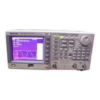
Tektronix AFG3022 Service Manual (164 pages)
Arbitrary/Function
Brand:
Tektronix
| Category:
Portable Generator
| Size: 8 MB
Table of Contents
Table of Contents
5
General Safety Summary
11
Service Safety Summary
13
Environmental Considerations
15
Preface
17
Finding Other Information
18
Manual Conventions
18
Introduction
19
Performance Verification Procedures
19
Strategy for Servicing
19
Tektronix Service Offerings
20
Specifications
21
Performance Conditions
23
Electrical
23
Table 1-1: Operation Mode
23
Table 1-2: Waveforms
24
Table 1-3: Frequency and Period
24
Table 1-4: Phase (Except DC, Noise, and Pulse)
26
Table 1-5: Lead Delay (Pulse)
26
Table 1-6: Amplitude
26
Table 1-7: DC Offset
27
Table 1-8: Internal Noise Add
27
Table 1-9: Output Characteristics
28
Table 1-10: Modulation
31
Inputs/Outputs
33
Table 1-11: Front Panel
33
General
34
Table 1-12: Rear Panel
34
Table 1-13: System Characteristics
34
Table 1-14: Power
35
Table 1-15: Environmental
35
Certifications and Compliances
36
Figure 1-1: AFG3000 Series Dimensions
39
Figure 1-2: RM3100 Rackmount Dimensions
39
Operating Information
41
Operating Basics
43
General Features
43
Table 2-1: General Features
43
Installation
44
Figure 2-1: Front Size
44
Protect Your Instrument from Misuse
45
Figure 2-2: Output and Input Connectors
45
Figure 2-3: Fuse Adapter
45
Floating Ground
46
Figure 2-4: Grounding Equivalent Circuit
46
Protect Your DUT
47
Powering the Instrument on and off
48
Self Test and Self Calibration
49
Getting Acquainted with Your Instrument
50
Figure 2-5: Front-Panel Controls
50
Figure 2-6: Rear Panel
51
Screen Interface
52
Figure 2-7: Screen Interface
52
Theory of Operation
53
Overview
55
Table 3-1: Combination of Circuit Boards Used in each Model
55
Figure 3-1: AFG3000 Series Block Diagram
56
Platform
57
Generator Section
58
Performance Verification
61
Self Tests
63
Performance Tests
65
Table 4-1: Performance Test Items
65
Table 4-2: Test Equipment
66
Test Record
67
Frequency/Period Test
82
Figure 4-1: Frequency/Period Tests
82
Amplitude Test
83
Figure 4-2: 50 Ohm Terminator Accuracy
83
Figure 4-3: Amplitude Tests
83
DC Offset Test
85
Figure 4-4: 50 Ohm Terminator Accuracy
85
Figure 4-5: DC Offset Tests
86
AC Flatness Test
88
Figure 4-6: AC Flatness Tests
88
Harmonics Distortion Test
90
Figure 4-7: Harmonic Distortion Tests
90
Total Harmonic Distortion Test
92
Figure 4-8: Total Harmonic Distortion Tests
92
Spurious Test
94
Figure 4-9: Spurious Tests
94
Rise-Fall Time Test
97
Figure 4-10: Rise-Fall Time Tests
97
Adjustment Procedures
99
Purpose
101
Table 5-1: Adjustments Performed after Repair
101
Equipment Required
102
Table 5-2: Test Equipment
102
Performance Conditions
103
Enable the Service Mode
103
Save Menu
103
Clear CAL Data Menu
103
Reference Clock
104
Figure 5-1: Reference Clock Adjustment
104
LF Adjustment
105
Figure 5-2: LF Adjustment
105
Flatness Adjustment
106
Figure 5-3: Flatness Adjustment
106
Spurious Adjustment
108
Figure 5-4: Spurious Adjustment
108
Trigger Delay Adjustment
110
Figure 5-5: Trigger Delay Adjustment
110
Setting the Serial Number
112
Setting the MAC Address
112
Maintenance
113
Preparation
115
Preventing ESD
115
Inspection and Cleaning
116
Table 6-1: External Inspection Check List
117
Table 6-2: Internal Inspection Check List
118
Removal and Installation Procedures
121
Adjustment after Repair
121
List of Modules
121
Summary of Procedures
122
Tools Required
122
Figure 6-1: Disassembly Order
122
Flip Feet
123
Figure 6-2: Removing and Installing the Flip Feet
123
Front-Panel Knob
124
Rear Case
124
Figure 6-3: Rear Case Removal
124
Figure 6-4: Pasting the Urethane Foam Gaskets
125
Top Cover
126
Front Case
126
Figure 6-5: Top Cover Removal
126
A75 Front-Panel Board
127
Figure 6-6: Front Case Removal
127
Figure 6-7: A75 Front-Panel Board Removal
127
Display Module
128
Output Board (Afg310X, Afg325X)
128
Figure 6-8: Display Module Removal
128
Separation of Rear Module and Main Chassis
129
Figure 6-9: Output Board Removal
129
Figure 6-10: Separation of the Rear Module and Main Chassis
130
Figure 6-11: Pull out the Rear Module
130
Inverter
131
Figure 6-12: Inverter Removal
131
Figure 6-13: Inverter Installation
131
Fan
132
Figure 6-14: Fan Removal
132
Power Supply
133
Figure 6-15: Power Supply Removal
133
A72 CPU Board
134
Figure 6-16: Remove the BNC Connectors
134
A82 BNC Insulator Board
135
Figure 6-17: CPU Board Removal
135
Generator Board
136
Figure 6-18: Generator Board Removal
136
A81 BNC Insulator Board, BNC Bracket
137
Figure 6-19: A81 BNC Insulator Board and BNC Bracket Removal
137
Troubleshooting
139
Required Tools and Equipment
139
Troubleshooting Tree
139
Table 6-3: Required Equipment
139
Figure 6-20: Platform Troubleshooting Procedure
140
Figure 6-21: Generator Troubleshooting Procedure
141
Diagnostics
142
Calibration
143
Error Codes
144
Table 6-4: Error Codes
144
Diagrams
147
Figure 7-1: Interconnection for AFG3011
149
Figure 7-2: Interconnection for Afg302Xb
150
Figure 7-3: Interconnection for Afg310X and Afg325X
151
Diagrams
153
Replaceable Parts List
153
Parts Ordering Information
155
Using the Replaceable Parts List
156
Figure 8-1: Exploded Diagram
161
Figure 8-2: Rear Modules
164
Advertisement
Advertisement
Related Products
Tektronix AFG3000 Series
Tektronix AFG3021
Tektronix AFG3252
Tektronix AFG3102
Tektronix AFG3251
Tektronix AFG310
Tektronix AFG320
Tektronix AFG2021
Tektronix AFG2000
Tektronix AFG 5101
Tektronix Categories
Test Equipment
Measuring Instruments
Amplifier
Portable Generator
Printer
More Tektronix Manuals
Login
Sign In
OR
Sign in with Facebook
Sign in with Google
Upload manual
Upload from disk
Upload from URL