Table of Contents
Advertisement
Quick Links
Advertisement
Table of Contents
Troubleshooting

Related Manuals for Zublin MZ5000


Summary of Contents for Zublin MZ5000
- Page 1 Operating instructions MZ5000...
-
Page 2: Table Of Contents
Table of contents - Introduction to the MZ 5000 motion detector Page 3 - Coverage area Page 4 - Reducing the coverage area Page 5 - Installation Page 6 - Important installation notes Page 7 - Connection, diagrams Page 7 + 8 - Operating modes/switch functions Page 9 - Detector settings (time/lux etc.) -
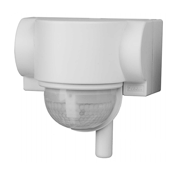
Page 3: Introduction To The Mz 5000 Motion Detector
Introduction - motion detector MZ 5000 motion detector The MZ 5000 motion detector is a passive infrared motion detector. It detects movements from heat sources (positive and negative ones) that stand out from the ambient temperature. The detection system is activated if the (passive) detection beams of the motion detector are intersected by unprotected parts of the body—... -
Page 4: Coverage Area
180° coverage area including 360° creep zone protection View from above Maximum range according to sensitivity Frontal detection high = approx. NOT SENSITIVE max.16 m approx. -50% medium = approx. max. 12 m Tangential detection low = approx. max. 8 SENSITIVE Side view The 180°... -
Page 5: Reducing The Coverage Area
Reducing the coverage area The range of the motion detector can be adjusted using the integrated left/right shutter. By turning Tilt R (right) or Tilt L (left) up, a maximum range of up 16 m can be achieved, by turning these down the range can be reduced to a minimum of 4 m. -
Page 6: Installation
Installation The MZ 5000 can be installed on walls and ceilings and can also be installed in external and internal corners using a separate adapter. Mounting plate One hole for Frontal view mounting to the ceiling Cable inlets (3x) One hole for mounting to the wall Two holes for... -
Page 7: Important Installation Notes
Important (installation) notes - Before starting to install the motion detector, ensure that the 230-volt power supply cable is de-energised using a voltage tester. - Any installations must be completed by trained specialists. - The MZ 5000 motion detector is designed for internal and external applications. -
Page 8: Connection, Diagrams Page 7
Diagrams Several motion detectors (max. three to four) including a short pulse function (SP) control the staircase timer switch, time relay (door bell, etc.) Parallel switching of several motion detectors including additional switch for continuous light. We recommend switching a maximum of three to four motion detectors in parallel, if the number of switching cycles is above average or in the event of increased (inductive) loads, we recommend using the short pulse function on the motion detector and switching the load via an... -
Page 9: Operating Modes/Switch Functions
Switch functions Standard connection diagram for the detector: the detector can be switched to the various modes via the breaker switch. Please note that for this function, the rhythm of the pulse and break times must be correctly adjusted. If a switch is used that is not directly next to the detector, cable interferences may interrupt this function, which is dependent on the installation, although there is no guarantee. - Page 11 MZ 5000 Controller Dusk Holiday mode and the light is switched on for the preset "DUSK TIME" (OFF or two to eight hours) once the brightness value falls below the value set with the "LUX" controller (it then switches to automatic mode). Relay 2 is not included in this function.
- Page 12 Time 2 Timer 2 can be used to determine how long relay 2 (isolated contact) shall remain on after the last movement is detected in the coverage area (short pulse approx. 0.7 seconds, pulse approx. 20 seconds, pause, timer of approx. min. 3 seconds to approx. max. 30 minutes). Tilt R Restricting the right coverage area (for characteristics see Tilt L) Time 1...
-
Page 13: Bi-Directional Swiss Garde Mz 5000
Bi-directional Swiss Garde MZ 5000 The Swiss Garde MZ 5000 can be extended to include the bi-directional function in a few simple steps. Remove the plug-in module at the rear of the sensor head and insert the bi-directional plug-in module (including antenna) in its place. -
Page 15: Control Pad (Cp) Key Assignment/Operation
Control pad (CP) Key assignment Please note: The relay 1 "Auto" button switches the holiday, party and ON modes to automatic. If a person is detected by the MZ 5000, the BiDi module transmits a "detection signal to the CP". The designated sound is then emitted by the CP and the LEDs on the control pad flash briefly. - Page 16 Learn button (lux value) The current lux value can be stored using the "Learn" button (operating threshold; light value on the motion detector that determines when the device should be activated). As soon as the required brightness is achieved, press the "Learn" button for three seconds, or twice within the space of five seconds.
- Page 17 Sound selection/acoustic signals Once a CP and detector have been paired, a different detection sound can then be assigned to each of the detectors on the CP. The channel selection switch on the back of the CP can be set to a channel of your choice, this assignment works in standard operation as well as in programming mode.
- Page 18 Programming button Press the programming button for one second to switch the CP to programming mode. You can now pair the CP with a MZ5000/BiDi module. Assign each motion detector a channel and when pairing ensure that the channel selection switch (1-2-3-4) on the rear of the CP is set to the required channel and that the programming button on the BiDi module has been activated.
-
Page 19: Preparing For Programming/Pairing
Programming/pairing the CP and BiDi module Only when both of the devices being paired (CP with BiDi module, or BiDi module with BiDi module) are in programming mode can they actually be paired. Safety: The CP and the BiDi module, or the BiDi module and BiDi module must be paired. -
Page 20: Programming The Cp To The Bidi Module
CP/BiDi module programming process Connect the power supply to the motion detector. The motion detector is ready for operation after approx. one minute (LED on the detector is switched off after permanent On mode is selected). 1. Press the programming button on the BiDi module for one second. (see page 13) The BiDi module switches to programming mode. -
Page 21: Programming A Bidi Module To A Bidi Module
6. The programming mode on the CP can be terminated prematurely by briefly pressing the programming button. If the programming process has not been successful, start again at Point 1. If this still does not work, both of the devices should be reset (press and hold the programming button for five seconds). -
Page 22: Deactivating The Transmitting Function On The Bidi Module
Deactivating the transmitting function on the BiDi module Would you like detector 1 to send an activation command to detector 2 but not the other way around, or would you prefer only one of the detectors to indicate a detection to the CP (tone)? To do so, you can block the transmitting function on the BiDi module by pressing and holding the relay 1 OFF button (see page 14) for five seconds. -
Page 23: Wireless Range
Wireless range 100 m in open areas The wireless transparency of walls cannot be standardised. Depending on the building materials used, ranges can either be aided (i.e. wood) or reduced (i.e. reinforced concrete). Attention: average values! Combination of one control pad, two MZ 5000s equipped with a BiDi module. -
Page 24: Troubleshooting (Motion Detector)
Troubleshooting (detector) Fault Cause/repair Electric load does not - Twilight value set too high switch: - Check the light's lamp - Check positioning of the manual switch - Check mains power supply/fuse Switches on and off - Check coverage area for something causing the without reason or does not fault: drafts, animals, heating, switch off again: etc. - Page 25 Important notes (wireless) Please note that the maximum wireless range is achieved in open areas. Any objects that are between the transmitter and receiver will reduce the signal. A good/average received signal can be expected when transmitting through wood or brick walls, however it is considerably more difficult to transmit through ceilings and concrete.
-
Page 26: Troubleshooting (Wireless)
Troubleshooting (wireless) Fault Cause/repair Detector cannot be - CP and BiDi module need to be operated with the CP paired (see Page 19 to 21). - Minimum distance of 2 m - Be aware of the dead spots, get closer to the detector and/or select an area with a better reception. -
Page 27: Notes
Transmitting range: max. 100 m (in an open area) approx. 20 to 50 m when operated manually Transmitting/receiving data: can be combined with a max. of four MZ5000/BiDi Alarm: Visual (LED) and acoustic (tone/sound) Tones/sounds: Seven different tones/sounds to indicate... -
Page 28: Technical Specifications
Do not dispose of electrical devices with your household waste, use municipality waste collection sites or return old devices to the retailer.
Need help?
Do you have a question about the MZ5000 and is the answer not in the manual?
Questions and answers