
Subscribe to Our Youtube Channel
Related Manuals for Security Tronix IP BUDDY+


Summary of Contents for Security Tronix IP BUDDY+
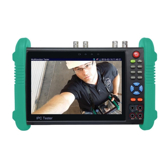
- Page 1 IP BUDDY+ ALL IN 1 CVI/TVI/AHD/SDI, IP & ANALOG CAMERA TEST METER WITH VIDEO MONITOR & MULTI METER Part number: ST-ALLIN1-TEST USER MANUAL v. 2.01.04.16 www.nacebrands.com www.securitytronix.com...
- Page 2 Thank you for purchasing the SecurityTronix IP BUDDY+ ALL IN 1 CVI/TVI/AHD/SDI, Analog and IP camera monitor with network tester! To use the IP BUDDY+ ALL IN 1 safely, please read the Safety Information carefully. This manual should be kept with the IP BUDDY+ ALL IN 1 for reference. Keep the serial number label for after-sale service within the warranty period.
-
Page 3: Table Of Contents
Table of Contents 1. Safety information ......................1 2. IP BUDDY+ ALL IN 1 Introduction .................. 1 2.1 General .......................... 1 2.2 Features ......................... 1 2.3 Function ........................2 2.4 Packing list ........................5 2.5 Operational buttons and description of connections............6 3. - Page 4 3.3.10 PING Test ......................24 3.3.11a/b Cable Test & Cable Search ................24 3.3.12 Port flashing....................... 25 3.3.13 Data monitor ...................... 25 3.3.14 Media Player ...................... 26 3.3.15 Audio player ...................... 26 3.3.16 LED lamp (Flashlight) ..................26 3.3.17 PoE in line Voltage test ..................27 3.3.18 Calculator ......................
-
Page 5: Safety Information
1. Safety information ◆ The IP BUDDY+ ALL IN 1 is intended for use in compliance with applicable codes and laws. ◆ Do not expose to moisture. ◆ Do not drop. ◆ The tester should not be charged over 8 hours. ◆... -
Page 6: Function
8GB Micro SD card included. LCD screen with adjustable brightness/contrast/color/saturation. Enhanced Color bar generator: PAL/NTSC multi-system color bar video generator (Eight-system switchable, transmit/receive eight-system colorful images). Ping test: PING is the most conventional network debugging tool; it is used for testing if the connected IP camera or other network equipment’s Ethernet port is working normally and the IP address is correct. - Page 7 2.3.5 Analog camera test (PTZ) This displays an analog camera image on the 7 inch 1280x800 LCD screen display. It supports PAL & NTSC formats. The LCD screen's back light brightness, video image brightness, contrast and color saturation are all adjustable. 2.3.6 CVI camera test This displays an HD CVI camera image.
- Page 8 2.3.15 Cable Search Identify different cables by use of an audio signal. This function enables the blue cable tracer’s copper pin to identify a cable that is connected to the IP Buddy+ by emitting an audible beeping noise. Cable search can be used when you have a bundle of cables but you need to identify a specific one.
-
Page 9: Packing List
2.3.28 PoE power supply The LAN port supports PoE 802.3at power at 48V and up to 24W. 2.3.29 HDMI signal output The HDMI output port supports up to a 1080p 60Hz resolution output. 2.3.30 Network bandwidth testing The network bandwidth test needs two IP BUDDY+ ALL IN 1 meters to test bandwidth: one as a transmitter, the other as a receiver. 2.3.31 Screen image rotates 180 degrees You can manually rotate the display 180 degrees using the settings. -
Page 10: Operational Buttons And Description Of Connections
2.5 Operational buttons and description of connections. Press more than 2 seconds, turn on or off the device ,short press to turn on or off the menu display Menu key 4x digital image zoom Far focus: Focus the image far away Near focus: Focus the image nearby TELE: zoom in the image WIDE: zoom out the image... - Page 11 Return/Close: Return or cancel while changing settings or close an app. Also close or decrease the aperture Multi meter inputs: Black/COM is NEGATIVE and Red is positive The charge indicator lights red while the battery is being charged. When the charging is complete, the indicator turns off automatically The RS485 data transmission indicator lights up red while data is being transmitted The data received indicator lights up red while data is being received...
-
Page 12: Operation
Audio output and headphone interface Audio input 5V 2A USB power output (used only for power, not data) 12VDC 2A charging interface 12VDC 2A power output , for provisional DC power supply 3. Operation 3.1 Installing the Battery The tester has a built-in lithium ion polymer rechargeable battery. Prior to the use of the unit, the battery cable connection behind the battery door needs to be connected and the unit fully charged for no more than 8 hours prior to use. -
Page 13: Coaxial Camera Connection
Warning:PoE switch or PSE power sourcing equipment can only be connected to the meter’s “PSE IN” port; otherwise it will damage the tester. 3.2.2 Coaxial camera connection (Analog/CVI/TVI/AHD/SDI) (1) Connect the camera's video output to the BNC VIDEO IN or CVI/TVI/AHD/SDI IN. Open the corresponding app (CVI, TVI, AHD, SDI or PTZ for analog) (2) IP BUDDY+'s “VIDEO OUT”... -
Page 14: Ptz (Activates Analog Video Viewing And Testing)
Local IP: This is the meter’s IP address. It will automatically change itself to match the IP camera once the connected camera is found. Discovery IP: Discovered IP address of cameras. If the camera is connected directly to the LAN port of the test meter, this will display only the camera’s IP address. - Page 15 Settings available are: A. Protocol Use the up and down arrow keys or tap the word “Protocols” to move the yellow cursor to “protocols” and activate this setting. This allows for setting a matching communication protocol from the IP BUDDY+ ALL IN 1 to the PTZ camera. (Most SecurityTronix PTZ cameras use PELCO-D) B.
- Page 16 When an image is displayed, press the button to enter the digital zoom mode, press it again to quit. Using two fingers on the touch screen, move outward or inward to zoom in and out on the image. When the image is enlarged, click left, right, upward or downward to move the image around.
- Page 17 (6) Photo When you click the “Photo” icon, it displays a gallery of saved still images on the screen. Select the thumbnail image you would like to view. Double-tap the image you want to view to make it full screen. Double-tap it again to return to the gallery. To rename or delete an image, click and hold on the file until this screen below appears: (7) Recorded video playback Click the “Playback”...
-
Page 18: Color-Bar Generator (Tv Out)
3.3.2 Color-bar generator (TV OUT) Click on the icon to open the Color-bar generator (TV OUT). The IP BUDDY+ ALL IN 1 meter sends the color bars via its VIDEO OUT BNC port. Click on the “PAL” button to switch between PAL or NTSC output formats. Select the different color bar choices at the bottom. To make the color bars full screen, double tap on the image. - Page 19 Address: Enter the camera’s address. The address setting must match the address of the camera. If they don’t match, you will not have PTZ control. Once you have your PTZ settings entered properly, you can control it by using touch screen commands. Tap left, right, up or down on the image to control the PTZ rotation direction and the camera will respond accordingly.
-
Page 20: Tvi Camera Test
To access the camera’s menu, click “Coaxitron” and select “Menu.” After you double check your settings, click OK and then click on the button to access the camera’s OSD menu. Use the arrow keys to navigate through the camera’s OSD menu. For snapshot, record and video playback, please refer to page 12. -
Page 21: Ahd Camera Test
Plug your TVI camera into the “TVI IN” BNC input at the top of the meter and the tester will automatically display the image resolution at the top of the screen. You may double tap on the screen to make the image display full screen. Double tap again to exit full screen mode. The meter supports the following TVI resolutions: 1280x720 @ 25/30/50/60 FPS &... -
Page 22: Sdi Camera Test
Enter in any necessary PTZ control settings and you should have PTZ control. For more information of operation of PTZ control, settings, snapshot, record and playback, please refer to the CVI PTZ section on page 16. 3.3.6 SDI Camera Test For SDI and SDI PTZ camera testing, click on the icon to open the SDI Camera Tester: Connect your SDI camera to the SDI BNC input at the top of the tester. - Page 23 Once you select ONVIF HD or RAPID mode, the meter automatically scans different network segments for ONVIF cameras. It lists the camera name and IP address on the Device List. If no cameras appear under the device list, try clicking on the Refresh button. If your IP camera does not appear after scanning the network, you can manually add an IP camera by clicking on the “Add”...
- Page 24 While in the “Live video” menu, click “Video Menu” at the top right of the image to access the following tools: Snapshot, Record, Photo, Playback, PTZ and Settings. ONVIF PTZ control: Tap the image in the direction you want the PTZ camera to move. Tap the left side of the image to move left, right to go right, up to go up and down to go down.
- Page 25 IP camera video settings: Click “Video Set” to enter the IP camera’s encoder and resolution settings. Make the desired changes and click “OK “to save. Image setting: Click “Imaging Set” to adjust image brightness, saturation, contrast, sharpness and backlight compensation mode. Network settings: Click “Network Set”...
-
Page 26: Ip Camera Test
Set:Click on the “Set” icon to change Snapshot and Video recording file name settings. You can set Auto storage, which sets filenames by time or set manual storage. Click “Sure” to save file name settings. Playback:Click the “Playback” icon to view saved videos. Double click the video you want to play. Click to return to the last menu. - Page 27 Click the icon to enter the IPC Test App. NOTE: WE STILL RECOMMEND YOU USE THE ONVIF APP TO VIEW IP CAMERAS. Note:Currently, the IPC Test App only supports some brands’ specific IP cameras; these include specific models made by SecurityTronix, ACTI, AXIS, Dahua, Hikvision, Samsung, SecurityTronix, and many more.
-
Page 28: Ip Address Scanner
3.3.9 IP address scanner Connect your network cable to the LAN port of the IP BUDDY+ ALL IN 1 meter and then click the icon to open the IP address scanner. Set your IP address search range by changing the Start and End IP addresses. Click the “Start” button to scan the IP address range. You can also input an IP address in the Port Number Scan to scan for open ports. -
Page 29: Port Flashing
3.3.11b Cable Search Connect a network cable to the UTP/SCAN port or connect a BNC cable to the “Video Out” port. Click the icon to open the Cable Search app. To switch between the different audio tones, select a number on the screen as seen below: Use the blue Combination cable identifier and network cable tester’s copper pointer to touch all the cables in the bundle you are searching at the other end. -
Page 30: Media Player
3.3.14 Media Player Click the icon to bring up the Media Player. The Media player can browse video and image files. It supports the video formats of MP4, H.264, MPEG4, and MKV. The IP BUDDY+’s recorded files can play directly via the Media player. The Media player will automatically display the video files from the SD card. Click on the desired file to play. -
Page 31: Poe In Line Voltage Test
While in the flashlight app, click the red button to turn on the LED lamp. Press it again to turn it off. If you don’t press the red button to shut off the lamp and press the button to exit the app, the lamp will stay on. Click the Time Setting button to set a timer that will shut off the lamp. 3.3.17 PoE in line Voltage test Click the icon to enter the PoE voltage in line measurement app. -
Page 32: Ip Camera Viewer
The IP camera and IP BUDDY+ ALL IN 1 must be on the same network segment for the browser to interface with the camera. If they are not in button or press “RETRUN” to exit. Open the “Settings” app from the main menu to change the IP Buddy+’s the same segment, click the network settings to match those of the IP camera. -
Page 33: Application Tools
Note: 1. Don’t input power into the “DC12/2A OUTPUT” port. 2. Make sure you plug in your IP camera to the LAN port prior to turning on PoE power. 3. Before turning on the PoE power output, please make sure the IP camera supports PoE power. Otherwise it may damage the IP camera. 3.3.22 Application tools Click the icon to open the Application Tools folder. - Page 34 a). Start the server:Click “Start Server” button to use the tester as a Server. It will display its IP address at the top of the screen. b). Start send packet test:Using the other IP BUDDY+, type in the Server's IP address at the top right corner of the screen. This app is used to send packets for network speed testing.
- Page 35 Notepad: Click on the Notepad icon to open the Notepad app. Click the “Save” key to save the contents Link monitor : Click the icon to open the Link Monitor app. This app is used to see if an IP address is occupied by other network devices. This will avoid new address conflicts.
-
Page 36: Digital Multi Meter
3.3.23 Digital Multi-Meter To open the Digital Multi-meter tool, click on the icon. You will see the following screen: 1) Symbols: U: DC Voltage Ũ: AC Voltage A: DC Current Ã: AC Current Ω: Resistance : Continuity : Diode Testing : Capacitance 2) Settings Manual and Auto Range... - Page 37 Your voltage measurement will appear on the IP BUDDY+ ALL IN 1. If the measurement is negative reverse the polarity of your test leads. C.) DC Current Measurement WARNING: The maximum current of the mA socket is 660mA. Over-current will destroy the fuse and damage the meter. ...
- Page 38 F.) Continuity Testing WARNING: Make sure you turn off all power to the circuit and discharge any capacitors prior to testing continuity. 1. Connect the black test lead to the “COM” jack and the red test lead to the “V/Ω” jack. 2.
-
Page 39: Tool Folder
3.3.24 Tool Folder Click the icon to open the Tool Folder. You can move desktop icons into the Tools Folder by pressing on the icon for a few seconds until the screen below appears: You can also move an icon back to the desktop by pressing on the icon for a few seconds until it asks you if you want to move the icon back to the Desktop. - Page 40 Brightness: Set the desired brightness of the IP BUDDY+ ALL IN 1 and adjust the sleep time settings. Volume: Change volume levels. SD Card: Displays SD Card Capacity. You can also format the SD card or unmount it before removing it. FTP server: Once the IP BUDDY+ ALL IN 1 connects to a network, a computer can be used to read the SD card files via FTP.
-
Page 41: Update
Turn off option:If you select “Fast turn off”, the tester will shut down faster but data will not saved. To avoid unnecessary problems, it is recommended not to use the “Fast turn off” option. 3.5 Update icon to open the Update menu. Select “Local Update” to update via the SD card or select “Online Update” to check for updates Click the on the internet. -
Page 42: 12Vdc 2A Power Output
Note: Please make sure a network cable is connected to the IP Buddy+’s LAN port ONLY. Before using the PoE power output, please make sure the IP camera supports PoE power; otherwise it will damage the IP camera. 3.9 12VDC 2A power output When the IP BUDDY+ ALL IN 1 is turned on, the 12VDC power output ON by default. -
Page 43: Specifications
4. Specifications – For more detailed inquiries, please call SecurityTronix tech support: 1-800-688-9282, option 3 and then option 2. Model ST-ALLIN1-TEST (IP BUDDY+ ALL IN 1) HD over Coax, Analog & IP Test Meter Display 7 inch Capacitive Touch screen LCD monitor with a 1920x800 resolution Network port 10/100M auto adjusting RJ45 WIFI... -
Page 44: Securitytronix Ip Buddy+ All In 1 Warranty
SECURITYTRONIX 2-Year Limited Warranty IP BUDDY+ Securitytronix. (The "Company") warrants to the Original Purchaser that the IP BUDDY+ ALL IN 1 meters are free from defects in workmanship or material under normal use. This warranty starts on the date of shipment of the hardware to the Original Purchaser. During the warranty period, the Company agrees to repair or replace, at its sole option, without charge to Original Purchaser, any defective component in the IP BUDDY+ ALL IN 1 series meters.
Need help?
Do you have a question about the IP BUDDY+ and is the answer not in the manual?
Questions and answers