Intel P4304XXMFEN2 Service Manual
Hide thumbs
Also See for P4304XXMFEN2:
- Spares/accessories list and configuration manual (54 pages) ,
- Service manual (108 pages)
Table of Contents
Advertisement
Quick Links
Advertisement
Table of Contents

Related Manuals for Intel P4304XXMFEN2


Summary of Contents for Intel P4304XXMFEN2
- Page 1 Intel® Server Chassis P4304XXMFEN2/P4304XXMUXX Product Family System Integration and Service Guide A guide providing instructions for the insertion and extraction of system components and available Intel accessories and spares Revision 2.0 July 2017 Intel® Server Products and Solutions...
- Page 2 Intel ® Server Chassis P4304XXMFEN2/P4304XXMUXX Product Family System Integration and Service Guide <This page is intentionally left blank.>...
- Page 3 Document Revision History Revision Date Modifications Number July 2017 Production Release...
- Page 4 Intel, the Intel logo, are trademarks of Intel Corporation in the U.S. and/or other countries. *Other names and brands may be claimed as the property of others.
-
Page 5: Safety Information
For supported product regulatory, product safety, and certification information, reference the Intel Server Products Safety and Regulatory Compliance document, rev 1.5 or later. The Intel® Server Chassis P4000 product family will be identified and referenced as Pr4000 in all product regulatory test reports, certificates, and compliance collaterals. - Page 6 Intel recommends the following steps be taken when performing any procedures described within this document or while performing service to any computer system.
- Page 7 BIOS Setup screens. Chapter 5 – System Packaging Assembly – Provides package assembly instructions when re-using the Intel packaging in which the system was originally shipped.
- Page 8 Intel ® Server Chassis P4304XXMFEN2/P4304XXMUXX Product Family System Integration and Service Guide Additional Information and Software For additional information about this family of products or any of their supported accessories, refer to the following resources available at http://www.intel.com/support. Table 1. Server Chassis References...
-
Page 9: Table Of Contents
Intel ® Server Chassis P4304XXMFEN2/P4304XXMUXX Product Family System Integration and Service Guide Table of Contents 1. Server Building Block System Integration and Service ..................1 Intel® Server Chassis Identification ..........................2 Server Building Block Installation ..........................4 1.2.1 Chassis Side Cover Removal / Installation ......................4 1.2.2... - Page 10 Installing the LSI IMR RAID 5 Key ..........................89 3.4.2 Removing the LSI IMR RAID 5 Key .......................... 89 Intel® Remote Management Module 4 Lite Key – Installation / Removal ..........90 3.5.1 Intel® RMM4 Lite Key Installation ..........................90 3.5.2...
- Page 11 Intel ® Server Chassis P4304XXMFEN2/P4304XXMUXX Product Family System Integration and Service Guide System Configuration and Recovery Jumpers ....................121 6.2.1 S2600CW Server Board Family ..........................121 6.2.2 S2600ST Server Board Family ..........................123 7. System Service – FRU Replacement ........................127 System Fan Assembly Removal / Installation ....................
- Page 12 List of Figures Figure 1. Intel® Server Chassis P4304XXMFEN2 – Features overview ................... 2 Figure 2. Intel® Server Chassis P4304XXMUXX – Optional Redundant Power Supplies ..........3 Figure 3. Removing the Chassis Side Cover ............................4 Figure 4. Installing the Chassis Side Cover ............................5 Figure 5.
- Page 13 Figure 45. Releasing Processor from Carrier Clip ........................36 Figure 46. Intel® Server Board S2600CW DIMM Slot Layout ....................37 Figure 47. Intel® Server Board S2600ST Product Family Memory Slot Layout .............. 38 Figure 48. Installing Memory ................................39 Figure 49. Removing Memory ................................39 Figure 50.
- Page 14 Intel ® Server Chassis P4304XXMFEN2/P4304XXMUXX Product Family System Integration and Service Guide Figure 68. Installing an NVMe Add-in Card – S2600CW Board Family ................54 Figure 69. 8x2.5” PCIe* SSD (NVMe) Combo Backplane Features – Only for S2600CW Board Family ....55 Figure 70.
- Page 15 Intel ® Server Chassis P4304XXMFEN2/P4304XXMUXX Product Family System Integration and Service Guide Figure 102. Removing the Cosmetic Top Board .......................... 80 Figure 103. Installing the Front Panel Module ..........................80 Figure 104. Installing a 5.25" Drive ..............................81 Figure 105. Installing the Rack Bezel Frame ..........................81 Figure 106.
- Page 16 Figure 155. Bumper Position on Server Board .......................... 137 Figure 156. Server Board Installation ............................138 Figure 157. P4304XXMFEN2 Cable Routing - S2600CW Server Board Family ............140 Figure 158. P4304XXMUXX Cable Routing - S2600CW Server Board Family ............. 141 Figure 159.
- Page 17 Intel ® Server Chassis P4304XXMFEN2/P4304XXMUXX Product Family System Integration and Service Guide List of Tables Table 1. Server Chassis References ..............................viii Table 2. System Utility Software ................................. viii Table 3. BIOS Setup: Keyboard Command Bar ......................... 102 Table 4. System Status LED State Definitions ..........................143 Table 5.
-
Page 19: Server Building Block System Integration And Service
Server Building Block System Integration and Service Purpose This chapter provides instructions for the integration of the following Intel server building blocks: Intel® Server Chassis P4304XXMFEN2 + Intel® Server Board S2600CW Intel® Server Chassis P4304XXMUXX + Intel® Server Board S2600CW + Power Supply Module Intel®... -
Page 20: Intel® Server Chassis Identification
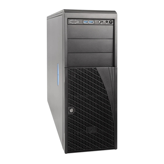
Intel ® Server Chassis P4304XXMFEN2/P4304XXMUXX Product Family System Integration and Service Guide Intel® Server Chassis Identification Figure 1. Intel® Server Chassis P4304XXMFEN2 – Features overview... -
Page 21: Figure 2. Intel® Server Chassis P4304Xxmuxx - Optional Redundant Power Supplies
Intel ® Server Chassis P4304XXMFEN2/P4304XXMUXX Product Family System Integration and Service Guide Figure 2. Intel® Server Chassis P4304XXMUXX – Optional Redundant Power Supplies Note: There may be only one filler present on the power supply positions. -
Page 22: Server Building Block Installation
® Server Chassis P4304XXMFEN2/P4304XXMUXX Product Family System Integration and Service Guide Server Building Block Installation As received, the Intel Server Chassis will include several components within a boxed accessory kit or placed within the chassis. 1.2.1 Chassis Side Cover Removal / Installation 1.2.1.1... -
Page 23: Figure 4. Installing The Chassis Side Cover
Intel ® Server Chassis P4304XXMFEN2/P4304XXMUXX Product Family System Integration and Service Guide 1.2.1.2 Chassis Side Cover Installation Figure 4. Installing the Chassis Side Cover 1. Place the chassis side cover onto the chassis and slide forward until the front edge of the cover is pressed up against the back edge of the front drive bay (see letter A). -
Page 24: Air Duct Removal / Installation
Intel ® Server Chassis P4304XXMFEN2/P4304XXMUXX Product Family System Integration and Service Guide 1.2.2 Air Duct Removal / Installation Always operate the server chassis with the air duct in place. The air duct is required for proper airflow within the server chassis. -
Page 25: Figure 6. Installing The Air Duct 1/4
Intel ® Server Chassis P4304XXMFEN2/P4304XXMUXX Product Family System Integration and Service Guide 1.2.2.2 Air Duct Installation Note: In order to avoid risk of damaging the server board and power cables, verify that the cable routing follows the recommendations described in Appendix B. -
Page 26: Figure 7. Installing The Air Duct 2/4
Intel ® Server Chassis P4304XXMFEN2/P4304XXMUXX Product Family System Integration and Service Guide Figure 7. Installing the Air Duct 2/4 3. Lower the air duct into the chassis in a tilted manner so that the two tabs in the front are securely installed in the chassis alignment holes first. -
Page 27: Installing The Io Shield
Intel ® Server Chassis P4304XXMFEN2/P4304XXMUXX Product Family System Integration and Service Guide 1.2.3 Installing the IO Shield Note: The IO shield can be found in the server board package or can be ordered separately. Figure 9. Installing the I/O Shield 1. -
Page 28: Installing The Stand-Off Screws
2. Install the stand-off screws to the chassis mounting holes, matching the positions in the chassis with the same label as shown in Figure 10. Note: The P4304XXMFEN2 and P4304XXMUXX chassis can support different boards. The standoff configuration shown above is the only valid configuration to install the S2600CW and S2600ST server board... -
Page 29: Server Board Installation
Intel ® Server Chassis P4304XXMFEN2/P4304XXMUXX Product Family System Integration and Service Guide 1.2.5 Server Board Installation Note: Follow ESD precautions outlined at the beginning of this document. Figure 11. Bumper Position on Server Board 1. Remove the server board from its anti-static bag. -
Page 30: Figure 12. Server Board Installation
Intel ® Server Chassis P4304XXMFEN2/P4304XXMUXX Product Family System Integration and Service Guide Figure 12. Server Board Installation 1. Carefully move aside any cables taped to the chassis base to clear the area for server board placement. 2. Carefully lower the server board into the chassis so that the rear I/O connectors of the server board align with it and are fully seated into the matching holes on the chassis back panel (see letter A). -
Page 31: Power Supply Installation (P4304Xxmuxx Chassis)
Intel ® Server Chassis P4304XXMFEN2/P4304XXMUXX Product Family System Integration and Service Guide 1.2.6 750W Power Supply Installation (P4304XXMUXX chassis) The P4304XXMUXX supports 750W or 1600W redundant power supplies that need to be ordered separately and installed in the server chassis. -
Page 32: 1600W Power Supply Installation (P4304Xxmuxx Chassis)
Intel ® Server Chassis P4304XXMFEN2/P4304XXMUXX Product Family System Integration and Service Guide 1.2.7 1600W Power Supply Installation (P4304XXMUXX chassis) Before inserting the 1600W power supply into the chassis, the power distribution board must be moved from its default position. Figure 14. PDB Location for 750W PSU 1. -
Page 33: Cable Connections
Intel ® Server Chassis P4304XXMFEN2/P4304XXMUXX Product Family System Integration and Service Guide Figure 16. Installing 1600W Power Supply 5. Remove one of the two power supply bay filler. 6. Insert the 1600W power supply module into the power supply bay until it clicks and locks into place. -
Page 34: Connecting The System Fan Cables To The Server Board
Connecting the System Fan Cables to the Server Board Figure 18. Connecting System Fan Cables 1. For server chassis P4304XXMFEN2, connect the cables of the two fixed system fans to the fan headers on the server board (silkscreen labeled “SYS_FAN_1” and “SYS_FAN_2”). -
Page 35: Connecting Cables From Front Panel To Server Board
Intel ® Server Chassis P4304XXMFEN2/P4304XXMUXX Product Family System Integration and Service Guide 1.3.3 Connecting Cables From Front Panel to Server Board 1.3.3.1 S2600CW Server Board Family Figure 19. Connecting Front Panel Cables - S2600CW Board Family 1. Connect the gray 24-pin front panel cable to the 2x12 SSI -compliant front panel header on the server board edge (silkscreen labeled “SSI_FRONT_PANEL”). -
Page 36: Essential System Component Installation
Intel ® Server Chassis P4304XXMFEN2/P4304XXMUXX Product Family System Integration and Service Guide Essential System Component Installation Purpose This chapter provides instructions for installing and removing essential system components, including processors, memory, storage devices, and add-in cards. Before You Begin Before working with your server product, observe the safety and ESD precautions found in the Warnings section at the beginning of this document. -
Page 37: Processor Installation / Removal
Intel ® Server Chassis P4304XXMFEN2/P4304XXMUXX Product Family System Integration and Service Guide Processor Installation / Removal 2.1.1 For S2600CW Server Board Family 2.1.1.1 Processor Heatsink(s) Removal Figure 21. Processor Heatsink Removal The heatsink is attached to the server board or processor socket with captive fasteners. Using a #2 Phillips* screwdriver, loosen the four screws located on the heatsink corners in a diagonal manner with this procedure: 1. -
Page 38: Figure 22. Processor Installation - Open The Socket Lever
Intel ® Server Chassis P4304XXMFEN2/P4304XXMUXX Product Family System Integration and Service Guide 2.1.1.2 Processor Installation Caution: The processor must be appropriate: If you install a processor that is inappropriate for your server, you may damage the server board. For a web link to the list of compatible processor(s), see “Additional Information and Software”. -
Page 39: Figure 24. Processor Installation - Install The Processor
Intel ® Server Chassis P4304XXMFEN2/P4304XXMUXX Product Family System Integration and Service Guide Notes: The underside of the processor has components that may damage the socket pins if installed improperly. The processor must align correctly with the socket opening before installation. DO NOT DROP the processor into the socket. -
Page 40: Figure 26. Processor Installation - Close The Load Plate
Intel ® Server Chassis P4304XXMFEN2/P4304XXMUXX Product Family System Integration and Service Guide 8. Close the load plate. 9. Carefully lower the load plate down over the processor. 10. Lock down the load plate. Figure 26. Processor Installation – Close the Load Plate Figure 27. -
Page 41: Figure 28. Processor Heatsink Installation
Intel ® Server Chassis P4304XXMFEN2/P4304XXMUXX Product Family System Integration and Service Guide 2.1.1.3 Processor Heatsink Installation Figure 28. Processor Heatsink Installation 1. If present, remove the protective film covering the Thermal Interface Material (TIM) on the bottom side of the heatsink (see letter A). -
Page 42: For S2600St Server Board Family
Intel ® Server Chassis P4304XXMFEN2/P4304XXMUXX Product Family System Integration and Service Guide 2.1.2 For S2600ST Server Board Family 2.1.2.1 Assembling the Processor Heat Sink Module (PHM) The Processor Heat Sink Module (PHM) refers to the sub-assembly where the heat sink and processor are clipped together prior to installation onto the server board. -
Page 43: Figure 30. Processor Reference Diagram - Top And Bottom Views Of Processor
Intel ® Server Chassis P4304XXMFEN2/P4304XXMUXX Product Family System Integration and Service Guide Required Tools: • T – 30 Torx screwdriver Flathead screwdriver • Adequate ESD protective gear (wrist strap, ESD mat) • Figure 30. Processor Reference Diagram - Top and Bottom Views of Processor WARNING: You may damage the processor heat sink when grasping the heat sink by the longer sides and squeezing the fins together. -
Page 44: Figure 31. Processor Heat Sink
Intel ® Server Chassis P4304XXMFEN2/P4304XXMUXX Product Family System Integration and Service Guide Figure 31. Processor Heat Sink CAUTION: Do not touch sensitive contacts on the bottom side of the processor at any time during PHM assembly or installation. Also refrain from touching the pins inside the processor socket as they also are extremely sensitive. -
Page 45: Figure 32. Alignment Features
Intel ® Server Chassis P4304XXMFEN2/P4304XXMUXX Product Family System Integration and Service Guide NOTE: The PHM and processor socket include several alignment features to ensure proper assembly and installation. Take care to ensure components are accurately assembled and the PHM is oriented correctly to the processor socket prior to installation. -
Page 46: Figure 33. Processor Carrier Clip Assembly
Intel ® Server Chassis P4304XXMFEN2/P4304XXMUXX Product Family System Integration and Service Guide 3. Orient the processor with the heat spreader side down so its alignment features match those of the carrier clip, as shown in the following figures. Figure 33. Processor Carrier Clip Assembly 4. -
Page 47: Figure 35. Processor And Carrierclip Sub-Assembly To Heat Sink
Intel ® Server Chassis P4304XXMFEN2/P4304XXMUXX Product Family System Integration and Service Guide 5. If present, remove the protective film covering the TIM on the bottom side of the heat sink. 6. Orient the processor sub-assembly over the processor heat sink so that all corner features are in alignment. -
Page 48: Figure 37. Removing The Plastic Socket Cover
Intel ® Server Chassis P4304XXMFEN2/P4304XXMUXX Product Family System Integration and Service Guide 2.1.2.2 Processor Heat-sink Module Installation 1. Remove the plastic processor socket cover through the following: a. Grasp the socket cover using the finger grips on each end as shown in the following figure (see letter A) then carefully pull up to remove (see letter B). -
Page 49: Figure 38. Phm Alignment To Bolster Plate
Intel ® Server Chassis P4304XXMFEN2/P4304XXMUXX Product Family System Integration and Service Guide 2. Install the PHM to the processor socket. 3. Align the mounting holes of the PHM (located on diagonal corners) to the bolster plate guide pins of the processor socket, as shown in the following figure. -
Page 50: Figure 39. Correct Placement Of Processor Socket Pin
Intel ® Server Chassis P4304XXMFEN2/P4304XXMUXX Product Family System Integration and Service Guide Note : Confirm proper PHM installation by visually checking whether or not the PHM sits level with the processor socket assembly. PHMs can only be fastened down if correctly installed. -
Page 51: Figure 40. Installing The Phm
Intel ® Server Chassis P4304XXMFEN2/P4304XXMUXX Product Family System Integration and Service Guide 5. Secure the PHM to the processor socket Assembly. Using a T30 Torx bit screwdriver, securely tighten (12 in-lb.) each fastener in the sequence shown on the label located on the top of the heat-sink. -
Page 52: Figure 41. Uninstalling The Phm
Intel ® Server Chassis P4304XXMFEN2/P4304XXMUXX Product Family System Integration and Service Guide 2.1.2.3 Processor Heat-sink Module Removal WARNING: Processor heat-sinks can become extremely hot during normal system operation. Before attempting to remove the processor from the server board, ensure that system power has been fully disconnected and allow the processor heat sinks to fully cool before attempting to remove the PHM from the server board. -
Page 53: Figure 43. Phm Disassembly
Intel ® Server Chassis P4304XXMFEN2/P4304XXMUXX Product Family System Integration and Service Guide 2.1.2.4 Processor Heat-sink Module Disassembly 1. Place the PHM (heat-sink down) onto a flat surface. 2. To remove the processor and clip sub-assembly from the heat sink, insert the head of a flat head screw driver in-between the heat sink and the processor clip assembly (as shown below) and gently twist until the bond between heat sink and the processor is broken. -
Page 54: Figure 44. Releasing The Processor Carrier Clip From The Heat Sink
Intel ® Server Chassis P4304XXMFEN2/P4304XXMUXX Product Family System Integration and Service Guide Figure 44. Releasing the Processor Carrier Clip from the Heat Sink 5. Remove the processor from the processor carrier clip by carefully pushing back one of the latches located on the ends of the processor and rotating the processor up and out of the processor carrier. -
Page 55: Memory Installation And Removal
Memory Slot Population Requirements 2.2.1.1 For S2600CW Server Board Family Note: For details on DIMM population rules, please refer to the Intel® Server Board S2600CW Product Family Technical Product Specification. DIMM Installation Order: Channels A, B, C, and D. Start with the 1 DIMM (Blue Slot) on each channel, then Slot 2. -
Page 56: Figure 47. Intel® Server Board S2600St Product Family Memory Slot Layout
2.2.1.2 For S2600ST Server Board Family Note: For details on DIMM population rules, please refer to the Intel® Server Board S2600ST Product Family Technical Product Specification. Each installed processor provides six memory channels. On the Intel® Server Board S2600ST product •... -
Page 57: Memory Installation
Intel ® Server Chassis P4304XXMFEN2/P4304XXMUXX Product Family System Integration and Service Guide 2.2.2 Memory Installation Figure 48. Installing Memory 1. Locate the DIMM slots. Make sure the clips at either end of the DIMM slot(s) are pushed outward to the open position (see letter A). -
Page 58: Storage Device Installation/Upgrade
Server Chassis P4304XXMFEN2/P4304XXMUXX Product Family System Integration and Service Guide Storage Device Installation/Upgrade The server chassis P4304XXMFEN2 and P4304XXMUXX support several different storage device options depending on the installed server board. This section provides instructions for the installation and upgrade of front drive bay storage devices. - Page 59 Intel ® Server Chassis P4304XXMFEN2/P4304XXMUXX Product Family System Integration and Service Guide Upgrade Option: One 2.5” drive bay with Hot-Swap backplane. Supports up to 8x2.5” drives • (SAS/SATA). Upgrade Option: One 2.5” drive bay with Hot-Swap backplane. Supports up to 4x2.5” drives •...
- Page 60 Intel ® Server Chassis P4304XXMFEN2/P4304XXMUXX Product Family System Integration and Service Guide For S2600ST board family: • Basic Configuration: Four 3.5” fixed drive trays are the default chassis configuration. Upgrade Option: One 3.5” drive bay with Hot-Swap backplane. Supports up to 4x3.5” drives.
- Page 61 Intel ® Server Chassis P4304XXMFEN2/P4304XXMUXX Product Family System Integration and Service Guide Upgrade Option: One optional 2.5” drive bay with Hot-Swap backplane. Supports up to 8x2.5” • drives (SAS/SATA/NVMe). • Upgrade Option: One 2.5” drive bay with dual port Hot-Swap backplane. Supports up to 8x2.5”...
-
Page 62: Removing The Front Bezel
Intel ® Server Chassis P4304XXMFEN2/P4304XXMUXX Product Family System Integration and Service Guide The table below shows the cables required for these storage drive options. Drive Configuration Cable Type Fixed drives (Default Mini-SAS HD to 7-pin SATA (AXXCBL450HD7S), connect Mini- configuration) SAS HD side to server board side and 7-pin SATA side to drives. -
Page 63: Installing The Front Bezel
Intel ® Server Chassis P4304XXMFEN2/P4304XXMUXX Product Family System Integration and Service Guide 2.3.2 Installing the Front Bezel Figure 51. Installing the Front Bezel 1. Fit the right edge of the bezel assembly against the right side of the chassis. 2. Engage the plastic bezel hooks (see letter A) into the raised metal slots at the chassis edge. -
Page 64: Installing A Fixed Mount Drive
2.3.3 Installing a Fixed Mount Drive The server chassis P4304XXMFEN2 and P4304XXMUXX support four 3.5” fixed drive trays with their default configuration. Additional fixed drive trays can be purchased (iPC - FUP4X35NHDK) in order to support up to 8 fixed drives. -
Page 65: Figure 53. Releasing The Fixed Drive Trays
Intel ® Server Chassis P4304XXMFEN2/P4304XXMUXX Product Family System Integration and Service Guide Figure 53. Releasing the Fixed Drive Trays 4. Release the fixed drive trays by pressing the latches on both sides of the tray and pull the drive trays until they are fully removed from the chassis. -
Page 66: Figure 55. Installing A Populated Fixed Drive Tray
Intel ® Server Chassis P4304XXMFEN2/P4304XXMUXX Product Family System Integration and Service Guide Figure 55. Installing a Populated Fixed Drive Tray 6. Slide the fixed drive tray back into the chassis until it clicks into place. Figure 56. Installing the EMI Cover 7. -
Page 67: Figure 57. Data Cable For Fixed Storage Drives Ipc- Axxcbl450Hd7S
Intel ® Server Chassis P4304XXMFEN2/P4304XXMUXX Product Family System Integration and Service Guide Locate the data cable for fixed storage drives (included in the accessory bag inside the chassis) and connect the cable connections using one of the on-board Mini-SAS HD SATA connectors as shown in Figure 58. -
Page 68: Upgrading The Fixed Drive Storage To 4X3.5" Or 8X2.5" Hot-Swap Drive Bay Storage
Intel ® Server Chassis P4304XXMFEN2/P4304XXMUXX Product Family System Integration and Service Guide 2.3.4 Upgrading the Fixed Drive Storage to 4x3.5” or 8x2.5” Hot-Swap Drive Bay Storage The server chassis supports fixed drive storage by default; optional 4x3.5” or 8x2.5” Hot-Swap drive bay kits and cables can be ordered separately and installed in the server chassis as an upgrade option. -
Page 69: Figure 60. Installing The Emi Cover
Intel ® Server Chassis P4304XXMFEN2/P4304XXMUXX Product Family System Integration and Service Guide Figure 60. Installing the EMI Cover 5. Install the EMI cover from the Hot Swap Drive Bay Kit, by aligning the tabs on the EMI cover to the chassis slots (see letter A) and slide it down (see letter B). -
Page 70: Figure 62. Connecting Data Cables For Hot-Swap Drive Bay Kit - S2600Cw Board Family
Intel ® Server Chassis P4304XXMFEN2/P4304XXMUXX Product Family System Integration and Service Guide 8. Cable connections. • S2600CW Server Board Family: Note: The following instructions apply when using the on-board connectors. Figure 62. Connecting Data Cables for Hot-Swap Drive Bay Kit – S2600CW Board Family a. -
Page 71: Figure 64. Data Cable For Hot-Swap Drive Bay Kit Ipc- Axxcbl380Hdhd
Intel ® Server Chassis P4304XXMFEN2/P4304XXMUXX Product Family System Integration and Service Guide 9. Plug the connector on the other end of the Mini-SAS HD cable to the backplane. MiniSAS (SVRBD/HSBP) XXXXXX-XXX YYWW Figure 64. Data Cable for Hot-Swap Drive Bay Kit iPC- AXXCBL380HDHD 10. -
Page 72: Upgrading The Fixed Drive Storage To 8X2.5" Pcie* Ssd (Nvme) Combo Drive Bay Storage
Intel ® Server Chassis P4304XXMFEN2/P4304XXMUXX Product Family System Integration and Service Guide 2.3.5 Upgrading the Fixed Drive Storage to 8x2.5” PCIe* SSD (NVMe) Combo Drive Bay Storage 2.3.5.1 For S2600CW Server Board Family The installation of the 8x2.5” SAS/PCIe* SSD (NVMe) combo drive bay involves several components: •... -
Page 73: Figure 69. 8X2.5" Pcie* Ssd (Nvme) Combo Backplane Features - Only For S2600Cw Board Family
Intel ® Server Chassis P4304XXMFEN2/P4304XXMUXX Product Family System Integration and Service Guide Label Description SMBus-Out (I²C OUT) cable connector for multi-backplane support SAS/SATA Ports 4-7 Mini-SAS HD cable connector PCIe* SSD Drive #3 Mini-SAS HD cable connector PCIe* SSD Drive #2 Mini-SAS HD cable connector... -
Page 74: Figure 70. 8X2.5" Pcie* Ssd (Nvme) Combo Backplane Front Side -S2600Cw Board Family Only
Intel ® Server Chassis P4304XXMFEN2/P4304XXMUXX Product Family System Integration and Service Guide The figure below shows the PCIe* SSD and SAS/SATA Drive Slots on the backplane. Figure 70. 8x2.5” PCIe* SSD (NVMe) Combo Backplane Front Side –S2600CW Board Family Only The cables used to connect the NVMe add-in card to the 8x2.5”... - Page 75 Intel ® Server Chassis P4304XXMFEN2/P4304XXMUXX Product Family System Integration and Service Guide Notes: The 8x2.5 SAS/NVMe Combo Backplane is capable of supporting 12Gb SAS or 6Gb SAS/SATA drives. The SAS/SATA drives are Hot-Swappable, and each drive is mounted to a drive tray with a green latch. The front side of the backplane includes eight drive slots.
-
Page 76: Figure 72. Data Cable Connectors For Pcie* Ssd Combo Hsbp - S2600St Board Family Only
Intel ® Server Chassis P4304XXMFEN2/P4304XXMUXX Product Family System Integration and Service Guide 2.3.5.2 For S2600ST Server Board Family The installation of the 8x2.5” SAS/PCIe* SSD (NVMe) Combo Drive Bay involves several components: 8x2.5” SAS/PCIe* SSD (NVMe) Combo Drive Bay (iPC AUP8X25S3NVDK) •... -
Page 77: Figure 73. 8X2.5" Pcie* Ssd (Nvme) Combo Backplane Features -For S2600St Board Family Only
In order to support NVMe RAID and NVMe Management features, the optional Intel® VROC Key must be installed on to the server board. With the Intel VROC key installed, specific drive population rules exist and must be followed for proper support of the NVMe management features. -
Page 78: Figure 75. Backplane Cabling From Two Pcie Sources
PCIe source are applied to the drive set connected to it Onboard PCIe OCuLink Connectors and / or Intel Tri-mode RAID module to 8 x 2.5” Combo Backplane The following information is applicable when PCIe signals to the 8x2.5” combo backplane are cabled from the PCIe OCuLink connectors located on the server board and/or an optionally installed Intel®... - Page 79 ALL other drive pairs on the backplane. The following illustrations identify supported and unsupported drive populations associated with any defined drive pair of the 8x2.5” combo backplane when Intel VROC is used for NVMe drive management. = Supported...
- Page 80 The following illustrations identify supported and unsupported drive populations associated with any defined drive set of the 8x2.5” combo backplane when an Intel® VROC key is installed to the server board and the PCIe source to the backplane is from an add-in PCIe Switch card.
- Page 81 NVMe Mixing of NVMe and SAS within a common drive set is not supported Note: The NVMe drive population rules defined above are only applicable when the Intel® VROC accessory option is installed and used to provide NVMe drive management.
-
Page 82: Upgrading The Fixed Drive Storage To 8X3.5" Hot-Swap Drive Bay Storage
Intel ® Server Chassis P4304XXMFEN2/P4304XXMUXX Product Family System Integration and Service Guide 2.3.6 Upgrading the Fixed Drive Storage to 8x3.5” Hot-Swap Drive Bay Storage The server chassis can support two 4x3.5” Hot-Swap drive bays as an upgrade option from fixed drive storage. -
Page 83: Figure 77. Interconnection Diagram For Two 4X3.5" Hot-Swap Drive Bay Kits
Intel ® Server Chassis P4304XXMFEN2/P4304XXMUXX Product Family System Integration and Service Guide Figure 77. Interconnection Diagram for Two 4x3.5” Hot-Swap Drive Bay Kits 6. Connect one end of the I²C cable to the HSBP_I²C header on the server board and the other end to the I²C_IN header on the backplane. -
Page 84: Upgrading The Fixed Drive Storage To 16X2.5" Hot-Swap Drive Bay Storage
Intel ® Server Chassis P4304XXMFEN2/P4304XXMUXX Product Family System Integration and Service Guide 2.3.7 Upgrading the Fixed Drive Storage to 16x2.5” Hot-Swap Drive Bay Storage The server chassis can support two 8x2.5” Hot-Swap drive bays as an upgrade option from fixed drive storage. -
Page 85: Figure 79. Connecting Data Cables For Two 8X2.5" Hot-Swap Drive Bay Kits - 2600Cw Board Family
Intel ® Server Chassis P4304XXMFEN2/P4304XXMUXX Product Family System Integration and Service Guide 5. Cable connections: S2600CW Server Board Family: Figure 79. Connecting Data Cables for Two 8x2.5” Hot-Swap Drive Bay Kits – 2600CW Board Family 6. Connect two of the Mini-SAS HD cables to the server board connectors labeled as SAS_0-3 and SAS_4-7 and one end of the I²C cable in the locations shown on the above illustration. -
Page 86: Figure 80. Interconnect Diagram For Two 8X2.5" Hot-Swap Drive Bay Kits - S2600Cw Board Family
Intel ® Server Chassis P4304XXMFEN2/P4304XXMUXX Product Family System Integration and Service Guide Figure 80. Interconnect Diagram for Two 8x2.5" Hot-Swap Drive Bay Kits – S2600CW Board Family S2600ST Server Board Family: • The server board only supports 8 drives connected through the on-board Mini-SAS HD connectors. -
Page 87: Drive Carrier Extraction, Installation, And Assembly For Standard Carrieers
Intel ® Server Chassis P4304XXMFEN2/P4304XXMUXX Product Family System Integration and Service Guide 2.3.8 Drive Carrier Extraction, Installation, and Assembly for Standard Carrieers Note: To maintain proper system cooling, all externally accessible drive bays must be populated with a drive carrier. Each drive carrier must have a hard disk drive (HDD), Solid State Device (SSD), or a supplied drive blank installed. -
Page 88: Figure 83. 3.5" Hard Disk Drive Installation - Removing The Drive Blank
Intel ® Server Chassis P4304XXMFEN2/P4304XXMUXX Product Family System Integration and Service Guide 2.3.8.3 3.5” Hard Disk Drive Installation Figure 83. 3.5” Hard Disk Drive Installation – Removing the Drive Blank 1. Remove the four screws securing the plastic drive blank to the carrier (see letter A). -
Page 89: Figure 85. Option To Install A 2.5" Ssd Into A 3.5" Carrier
Intel ® Server Chassis P4304XXMFEN2/P4304XXMUXX Product Family System Integration and Service Guide 2.3.8.4 Option to Install a 2.5” SSD into a 3.5” Carrier The 3.5” drive blank can be used as a 2.5” SSD bracket. Figure 85. Option to Install a 2.5” SSD into a 3.5” Carrier 1. -
Page 90: Drive Carrier Extraction, Installation, And Assembly For Tool-Less Drive Carriers
Intel ® Server Chassis P4304XXMFEN2/P4304XXMUXX Product Family System Integration and Service Guide Figure 87. 2.5” Storage Device Installation – Mounting the Drive to the Carrier 3. Install the storage device into the carrier. Verify the connector end of the drive is located towards the back of the carrier (see letter A). -
Page 91: Figure 89. Drive Carrier Into Chassis Installation
Intel ® Server Chassis P4304XXMFEN2/P4304XXMUXX Product Family System Integration and Service Guide 2.3.9.2 Drive Carrier Installation Figure 89. Drive Carrier into Chassis Installation 1. Align the drive assembly with the open drive bay 2. With the lever in the open position, insert the drive assembly into the drive bay (See letter A) and push forward until the drive makes contact with the backplane 3. -
Page 92: Figure 91. 2.5" Drive Carrier Assembly - Drive Installation To Carrier
Intel ® Server Chassis P4304XXMFEN2/P4304XXMUXX Product Family System Integration and Service Guide Mounting Tab (2 on each side) Mounting Holes (2 on each side) Figure 91. 2.5” Drive Carrier Assembly – Drive Installation to Carrier 2. With the rear drive connector positioned towards the back of the drive carrier, align and position the mounting holes on one side of the drive over the mounting tabs located on the drive carrier side rail (See letter “A”) -
Page 93: Figure 93. 3.5" Drive Carrier Assembly - Drive / Drive Blank Removal
Intel ® Server Chassis P4304XXMFEN2/P4304XXMUXX Product Family System Integration and Service Guide 2.3.9.4 3.5” HDD/SSD Drive Carrier Assembly Figure 93. 3.5" Drive Carrier Assembly - Drive / Drive Blank Removal 1. Remove the drive or drive blank from the carrier by holding the carrier assembly top side down in your right hand. -
Page 94: Figure 95. 3.5" Drive Carrier Assembly - Drive Blank Removal
Intel ® Server Chassis P4304XXMFEN2/P4304XXMUXX Product Family System Integration and Service Guide Note: Due to degraded performance and reliability concerns, the use of the 3.5” drive blank as a 2.5” drive bracket is intended to support SSD type storage devices only. Installing a 2.5” hard disk drive into the 3.5”... -
Page 95: Figure 97. 3.5" Drive Carrier To 2.5" Ssd Bracket - Mount Ssd To Bracket
Intel ® Server Chassis P4304XXMFEN2/P4304XXMUXX Product Family System Integration and Service Guide Figure 97. 3.5" Drive Carrier to 2.5” SSD Bracket – Mount SSD to Bracket 3. Mount and secure a 2.5” SSD to the drive bracket using two screws at the locations shown above (See letter “D”). -
Page 96: Figure 99. 3.5" Drive Carrier To 2.5" Ssd Bracket - Secure Ssd To Carrier
Intel ® Server Chassis P4304XXMFEN2/P4304XXMUXX Product Family System Integration and Service Guide Figure 99. 3.5" Drive Carrier to 2.5” SSD Bracket – Secure SSD to Carrier 7. Using two (2) screws, secure the SSD to the carrier side rail (See letter “G”) -
Page 97: Converting The Pedestal Chassis To Rack Mount Chassis
Intel ® Server Chassis P4304XXMFEN2/P4304XXMUXX Product Family System Integration and Service Guide Converting the Pedestal Chassis to Rack Mount Chassis 2.4.1 Removing the Front Panel Module Figure 100. Removing the Front Panel Module 1. Press the clip (see letter A). -
Page 98: Removing The Cosmetic Top Board
Intel ® Server Chassis P4304XXMFEN2/P4304XXMUXX Product Family System Integration and Service Guide 2.4.3 Removing the Cosmetic Top Board Figure 102. Removing the Cosmetic Top Board 1. Press the clip (see letter A). 2. Separate the top board from the chassis (see letter B). -
Page 99: Installing A 5.25" Drive (Optional)
Intel ® Server Chassis P4304XXMFEN2/P4304XXMUXX Product Family System Integration and Service Guide 2.4.5 Installing a 5.25” Drive (Optional) Figure 104. Installing a 5.25" Drive 1. Attach the slides (included with the chassis) to the optical drive by pressing the slides firmly into the side dimples on the optical drive (see letter A). -
Page 100: Installing The Rack Mount Handles And Bezel
Intel ® Server Chassis P4304XXMFEN2/P4304XXMUXX Product Family System Integration and Service Guide 2.4.7 Installing the Rack Mount Handles and Bezel Figure 106. Installing the Rack Mount Handles 1. Align the screw holes in the rack handles with the screw holes in the chassis. -
Page 101: Figure 108. Locking The Rack Mount Bezel
Intel ® Server Chassis P4304XXMFEN2/P4304XXMUXX Product Family System Integration and Service Guide Figure 108. Locking the Rack Mount Bezel 5. Lock the front bezel by inserting the key that comes included with the rack bezel door kit (IPC- AUPBEZEL4UD) and turning it anti-clockwise. -
Page 102: Option And Accessory Kit Integration And Service
Intel ® Server Chassis P4304XXMFEN2/P4304XXMUXX Product Family System Integration and Service Guide Option and Accessory Kit Integration and Service Purpose This chapter provides instructions for the integration of system components within a server chassis that has the server board and other system components pre-installed. It includes installation instructions for supported system options and other available accessory option kits. -
Page 103: Optical Drive - Installation And Removal
Intel ® Server Chassis P4304XXMFEN2/P4304XXMUXX Product Family System Integration and Service Guide Optical Drive – Installation and Removal This section provides installation and removal instructions for an installed SATA optical drive for systems that support the option. 3.1.1 Optical Drive Installation Note: The optical drive is NOT Hot-Swappable. -
Page 104: Optical Drive Removal
Intel ® Server Chassis P4304XXMFEN2/P4304XXMUXX Product Family System Integration and Service Guide Figure 110. Installing the Optical Drive 3. Locate the slides from the chassis side (see letter B). Attach the slides to the optical drive by pressing the slides firmly into the side dimples on the optical drive (see letter C). slide the drive into the device bay until it snaps into place (see letter D). -
Page 105: Esrt2 Raid5 Key - Installation / Removal
Intel ® Server Chassis P4304XXMFEN2/P4304XXMUXX Product Family System Integration and Service Guide Figure 112. Re-inserting the Empty EMI Shield 3. If you do not replace an optical drive with another drive, reinsert an EMI shield into the chassis. ESRT2 RAID5 Key – Installation / Removal 3.2.1... -
Page 106: Removing The Esrt2 Raid 5 Key
Intel ® Server Chassis P4304XXMFEN2/P4304XXMUXX Product Family System Integration and Service Guide 3.2.2 Removing the ESRT2 RAID 5 Key 1. Power off the system and disconnect the power cable(s). 2. Remove the chassis side cover. 3. Using the key pull tab, pull the key up until it disengages from the connector. -
Page 107: Lsi Imr Raid5 Key - Installation / Removal (S2600Cw Server Board Family Only)
Intel ® Server Chassis P4304XXMFEN2/P4304XXMUXX Product Family System Integration and Service Guide LSI IMR RAID5 Key – Installation / Removal (S2600CW Server Board Family Only) 3.4.1 Installing the LSI IMR RAID 5 Key Figure 115. IMR RAID 5 Key Location 1. -
Page 108: Intel® Remote Management Module 4 Lite Key - Installation / Removal
1. Remove the Intel® RMM4 Lite key from its packaging. 2. Locate the Intel® RMM4 Lite connector on the server board between the first two PCIe* slots. 3. Place the Intel® RMM4 Lite key over the connector and match the orientation of the key to that of the connector. -
Page 109: Trusted Platform Module (Tpm) Installation
Intel ® Server Chassis P4304XXMFEN2/P4304XXMUXX Product Family System Integration and Service Guide Trusted Platform Module (TPM) Installation 3.6.1 For S2600CW Server Board Family Figure 117. Platform Module (TPM) Installation – S2600CW Board Family 1. Locate the TPM module connector on the server board near the first PCIe* slot. -
Page 110: M.2 Storage Device Installation
Intel ® Server Chassis P4304XXMFEN2/P4304XXMUXX Product Family System Integration and Service Guide M.2 Storage Device Installation 3.7.1 For S2600CW Server Board Family Figure 119. M.2 Storage Device Installation - S2600CW Board Family 1. Locate the M.2 connector on the server board near the DIMM slot. -
Page 111: For S2600St Server Board Family
Intel ® Server Chassis P4304XXMFEN2/P4304XXMUXX Product Family System Integration and Service Guide 3.7.2 For S2600ST Server Board Family The server board supports two M.2 storage devices in a stacked configuration secured by a bracket. The following illustration shows the location for both the connectors and the bracket. -
Page 112: Figure 122. Installing Two M.2 Storage Devices (Dual Configuration)
Intel ® Server Chassis P4304XXMFEN2/P4304XXMUXX Product Family System Integration and Service Guide 3.7.2.2 Installing Two M.2 Devices (Dual Configuration) Figure 122. Installing Two M.2 Storage Devices (Dual Configuration) 1. Locate the M.2 connectors on the server board near the DIMM slots. -
Page 113: Lan Riser Installation (S2600St Server Board Family Only)
Intel ® Server Chassis P4304XXMFEN2/P4304XXMUXX Product Family System Integration and Service Guide LAN Riser Installation (S2600ST Server Board Family Only) The LAN Riser features two SFP+ ports and can be installed in any of the S2600ST models. A dedicated slot aligned with PCIe* Slot 5 is provided for the accessory card to communicate with the PCH and the BMC;... -
Page 114: Figure 124. Installing The Lan Riser 1/3
Intel ® Server Chassis P4304XXMFEN2/P4304XXMUXX Product Family System Integration and Service Guide Figure 124. Installing the LAN Riser 1/3 To install the LAN Riser: 1. Remove the chassis side cover following instructions in Section 1.2.1. 2. Remove the air duct following instructions in Section 1.2.2.1. -
Page 115: Figure 125. Installing The Lan Riser 2/3
Intel ® Server Chassis P4304XXMFEN2/P4304XXMUXX Product Family System Integration and Service Guide Figure 125. Installing the LAN Riser 2/3 6. Install the LAN riser in PCIe* Slot 5 on the server board (see letter D). Figure 126. Installing the LAN Riser 3/3 7. -
Page 116: Bbu Bracket Installation / Removal
Intel ® Server Chassis P4304XXMFEN2/P4304XXMUXX Product Family System Integration and Service Guide BBU Bracket Installation / Removal The Battery Backup Unit (BBU) bracket (iPC – AXXSTBBUBRKT) is an optional accessory kit that supports up to 3 Raid Maintenance Free Backup Units (RMFBU) and can be installed in any of the 5.25” device bays. -
Page 117: Bbu Bracket Removal
Intel ® Server Chassis P4304XXMFEN2/P4304XXMUXX Product Family System Integration and Service Guide 3.9.2 BBU Bracket Removal Figure 128. Removing the BBU Bracket 1. Press on the slide release latches (see letter A) and pull the BBU bracket or slide assembly from the chassis (see letter B). -
Page 118: Connecting The Aux Power-In Cable
216 W of additional power to the server board. On the Intel chassis P4304XXMUXX, this connector is cabled to a matching 2x2 connector on the power distribution board. A power budget for the complete system should be performed to determine how much supplemental power is available to support any high power add-in cards. -
Page 119: System Software Updates And Configuration
SDR data. A default software stack is loaded during the system manufacturing process. However, it may not be the latest available. For best operation and system reliability, it is highly recommended to update the system software stack to the latest available. Download the latest system software stack at this Intel web site: http://downloadcenter.intel.com At a minimum, after the initial configuration, you MUST update the system’s FRU and SDR data to ensure that... -
Page 120: Navigating The Bios Setup Utility
Intel ® Server Chassis P4304XXMFEN2/P4304XXMUXX Product Family System Integration and Service Guide 4.2.3 Navigating the BIOS Setup Utility The BIOS Setup Utility consists of several menu screens, each holding either informational fields and/or configurable system setup options. The bottom right portion of each menu screen provides a list of commands used to navigate through the Setup Utility. - Page 121 Intel ® Server Chassis P4304XXMFEN2/P4304XXMUXX Product Family System Integration and Service Guide Option Description <F9> Setup Defaults Press the <F9> key to display: Load Optimized Defaults? If “Yes” is highlighted and you press <Enter>, all setup fields are set to their default values. If “No” is highlighted and you press <Enter>, or, if you press the <Esc>...
-
Page 122: System Packaging Assembly Instructions
Server Chassis P4304XXMFEN2/P4304XXMUXX Product Family System Integration and Service Guide System Packaging Assembly Instructions The original Intel packaging in which the server system was delivered, is designed to provide protection to a fully configured system and was tested to meet ISTA (International Safe Transit Association) Test Procedure 3A (2008). - Page 123 Intel ® Server Chassis P4304XXMFEN2/P4304XXMUXX Product Family System Integration and Service Guide 2. Place the two pieces of side wall foam as shown. 3. Place two more pieces of side wall foam as shown.
- Page 124 Intel ® Server Chassis P4304XXMFEN2/P4304XXMUXX Product Family System Integration and Service Guide 4. Place the foam insert as shown. 5. Carefully place the system into the shipping bag and tape the bag shut. 6. Carefully lower the system into the inner shipping box as shown.
- Page 125 Intel ® Server Chassis P4304XXMFEN2/P4304XXMUXX Product Family System Integration and Service Guide 7. Fold the top flaps of the inner box closed, end flaps first, followed by side flaps. 8. Fold the top flaps of the outer box closed, end flaps first, followed by the side flaps.
-
Page 126: System Service - System Features Overview
Server Chassis P4304XXMFEN2/P4304XXMUXX Product Family System Integration and Service Guide System Service - System Features Overview This chapter provides a reference to locate and identify the features associated with the Intel® Server Board S2600CW and S2600ST product families, and Intel® Server Chassis P4304XXMFEN2/P4304XXMUXX product family. -
Page 127: Front Drive Bay Options
Intel ® Server Chassis P4304XXMFEN2/P4304XXMUXX Product Family System Integration and Service Guide Figure 131. Intel® Server Chassis P4304XXMUXX Overview 6.1.1 Front Drive Bay Options For S2600CW board family: •... - Page 128 Intel ® Server Chassis P4304XXMFEN2/P4304XXMUXX Product Family System Integration and Service Guide Basic Configuration: Four 3.5” fixed drive trays are the default chassis configuration. Upgrade Option: One 3.5” drive bay with Hot-Swap backplane. Supports up to 4x3.5” drives. Upgrade Option: Two 3.5” drive bays with Hot-Swap backplanes. Support up to 8x3.5 drives.
- Page 129 Intel ® Server Chassis P4304XXMFEN2/P4304XXMUXX Product Family System Integration and Service Guide Upgrade Option: One 2.5” drive bay with Hot-Swap backplane. Supports up to 8x2.5” drives • (SAS/SATA). • Upgrade Option: One 2.5” drive bay with Hot-Swap backplane. Supports up to 4x2.5” drives (SAS/SATA) with green latch for Hot-Swap support and 4x2.5 PCIe* SSDs (NVMe) with blue latch...
- Page 130 Intel ® Server Chassis P4304XXMFEN2/P4304XXMUXX Product Family System Integration and Service Guide For S2600ST board family: • Basic Configuration: Four 3.5” fixed drive trays are the default chassis configuration. Upgrade Option: One 3.5” drive bay with Hot-Swap backplane. Supports up to 4x3.5” drives.
-
Page 131: Control Panel Features
Intel ® Server Chassis P4304XXMFEN2/P4304XXMUXX Product Family System Integration and Service Guide Upgrade Option: One optional 2.5” drive bay with Hot-Swap backplane. Supports up to 8x2.5” • drives (SAS/SATA/NVMe). • Upgrade Option: One 2.5” drive bay with dual port Hot-Swap backplane. Supports up to 8x2.5”... -
Page 132: Back Panel Features
Intel ® Server Chassis P4304XXMFEN2/P4304XXMUXX Product Family System Integration and Service Guide 6.1.3 Back Panel Features Figure 133. P4304XXMFEN2 Back Panel Figure 134. P4304XXMUXX Back Panel... -
Page 133: Server Board Features
Intel ® Server Chassis P4304XXMFEN2/P4304XXMUXX Product Family System Integration and Service Guide 6.1.4 Server Board Features 6.1.4.1 S2600CW Server Board Family Figure 135. Server Board Feature Identification... -
Page 134: Figure 136. Intel® Light-Guided Diagnostic Leds - Server Board
Intel ® Server Chassis P4304XXMFEN2/P4304XXMUXX Product Family System Integration and Service Guide Callout Description System Status LED System ID LED LSB 1 2 3 4 5 6 POST Code Diagnostic LEDs Figure 136. Intel® Light-Guided Diagnostic LEDs – Server Board... -
Page 135: Figure 137. Dimm Fault Leds
Intel ® Server Chassis P4304XXMFEN2/P4304XXMUXX Product Family System Integration and Service Guide Figure 137. DIMM Fault LEDs... -
Page 136: Figure 138. Server Board Feature Identification
Intel ® Server Chassis P4304XXMFEN2/P4304XXMUXX Product Family System Integration and Service Guide 6.1.4.2 S2600ST Server Board Family Figure 138. Server Board Feature Identification... -
Page 137: Figure 139. Intel® Light-Guided Diagnostic Leds - Server Board
Intel ® Server Chassis P4304XXMFEN2/P4304XXMUXX Product Family System Integration and Service Guide Figure 139. Intel® Light-Guided Diagnostic LEDs – Server Board... -
Page 138: Figure 140. Dimm Fault Leds
Intel ® Server Chassis P4304XXMFEN2/P4304XXMUXX Product Family System Integration and Service Guide Figure 140. DIMM Fault LEDs... -
Page 139: System Configuration And Recovery Jumpers
Intel ® Server Chassis P4304XXMFEN2/P4304XXMUXX Product Family System Integration and Service Guide System Configuration and Recovery Jumpers 6.2.1 S2600CW Server Board Family Figure 141. System Configuration and Recovery Jumpers... - Page 140 Intel ® Server Chassis P4304XXMFEN2/P4304XXMUXX Product Family System Integration and Service Guide Jumper Name Jumper Purpose BIOS Recover In the unlikely event the system BIOS gets corrupted, the system automatically loads an embedded backup image of the BIOS. If for any reason the BIOS backup is not automatically installed, the BIOS recovery jumper can force the system to boot to the uEFI shell and allow a manual BIOS update.
-
Page 141: S2600St Server Board Family
Intel ® Server Chassis P4304XXMFEN2/P4304XXMUXX Product Family System Integration and Service Guide 6.2.2 S2600ST Server Board Family Figure 142. Configuration and Recovery Jumpers... - Page 142 Intel ® Server Chassis P4304XXMFEN2/P4304XXMUXX Product Family System Integration and Service Guide 6.2.2.1 BIOS Default Jumper Block This jumper resets BIOS options, configured using the <F2> BIOS Setup Utility, back to their original default factory settings. Note: This jumper does not reset Administrator or User passwords. In order to reset passwords, the Password Clear jumper must be used 1.
- Page 143 This jumper should only be used if the ME firmware has gotten corrupted and requires re-installation. The following procedure should be followed. Note: System Update files are included in the System Update Packages (SUP) posted to Intel’s Download center web site.
- Page 144 This jumper is NOT used when the BIOS is operating normally and you need to update the BIOS from one version to another. The following procedure should be followed. Note: System Update Packages (SUP) can be downloaded from Intel’s download center web site. http://downloadcenter.intel.com 1. Turn off the system 2.
-
Page 145: System Service - Fru Replacement
Intel ® Server Chassis P4304XXMFEN2/P4304XXMUXX Product Family System Integration and Service Guide System Service – FRU Replacement System Fan Assembly Removal / Installation System fan assembly removal is required whenever routing cables inside the chassis from back to front or from front to back, or when server board replacement is necessary. -
Page 146: Figure 144. Fixed System Fan Removal
® Server Chassis P4304XXMFEN2/P4304XXMUXX Product Family System Integration and Service Guide To Remove the Fixed System Fan (CPU fan or PCIe* fan) from P4304XXMFEN2 Figure 144. Fixed System Fan Removal 1. Unplug the fan cable from the server board (see letter A). -
Page 147: System Fan Assembly Installation
Intel ® Server Chassis P4304XXMFEN2/P4304XXMUXX Product Family System Integration and Service Guide 7.1.2 System Fan Assembly Installation To Install the Hot-Swap System Fan on P4304XXMUXX Figure 145. Hot-Swap System Fan Installation 1. Align the two guide pins on the top back side of the fan with the key slots located on the fan bracket. -
Page 148: Figure 146. Fixed System Fan Installation
Intel ® Server Chassis P4304XXMFEN2/P4304XXMUXX Product Family System Integration and Service Guide To Install the Fixed System Fan on P4304XXMFEN2 Figure 146. Fixed System Fan Installation 1. Route the fixed fan cable through the fan holder from front to back using the holes to the corner closer to the center of the fan bracket assembly (see letter A). -
Page 149: Replacing The System Battery
Intel ® Server Chassis P4304XXMFEN2/P4304XXMUXX Product Family System Integration and Service Guide Replacing the System Battery The battery on the server board powers the Real Time Clock for up to 10 years in the absence of power. When the battery starts to weaken, it loses voltage, and stored server settings and system clock and date settings may be lost. -
Page 150: Figure 147. Replacing The Backup Battery
Intel ® Server Chassis P4304XXMFEN2/P4304XXMUXX Product Family System Integration and Service Guide Figure 147. Replacing the Backup Battery 1. Locate the battery on the server board. 2. Gently press the metal clip as shown to release the battery (see letter “A”). -
Page 151: Replacing The Standard Front Panel
Intel ® Server Chassis P4304XXMFEN2/P4304XXMUXX Product Family System Integration and Service Guide Replacing the Standard Front Panel 7.3.1 Removing the Front Panel 1. Remove the chassis side cover following instructions in Section 1.2.1. 2. Remove the front bezel following instructions in Section 2.3.1. -
Page 152: Installing The Front Panel Module
Intel ® Server Chassis P4304XXMFEN2/P4304XXMUXX Product Family System Integration and Service Guide Figure 150. Removing the Front Panel Board 6. Unscrew the front panel board (see letter A). 7. Remove the front panel board from the module tray (see letter B). -
Page 153: Figure 152. Installing The Front Panel
Intel ® Server Chassis P4304XXMFEN2/P4304XXMUXX Product Family System Integration and Service Guide Figure 152. Installing the Front Panel 1. Slide the front panel module in the chassis until it snaps into place. Figure 153. Connecting the Front Panel 2. Connect the flat ribbon front panel cable and the 2-pin chassis intrusion cable to the front panel board. -
Page 154: Replacing The Server Board
Remove air duct by following instructions in section 1.2.2.1. Disconnect all cables attached to PCIe* add-in cards (if installed). Remove all options installed onto the server board including (if installed): Intel® RAID 5 option key, Intel® RMM 4 Lite key, TPM Module, and any installed PCIe* add-in cards. -
Page 155: Server Board Installation
Intel ® Server Chassis P4304XXMFEN2/P4304XXMUXX Product Family System Integration and Service Guide 7.4.2 Server Board Installation Note: Follow ESD precautions outlined at the beginning of this manual. Figure 155. Bumper Position on Server Board 1. Remove the server board from its anti-static bag. -
Page 156: Figure 156. Server Board Installation
Intel ® Server Chassis P4304XXMFEN2/P4304XXMUXX Product Family System Integration and Service Guide Figure 156. Server Board Installation 1. Carefully move aside any cables around the chassis base to clear the area for server board placement. 2. Carefully lower the server board into the chassis so that the rear I/O connectors of the server board align with it and are fully seated into the matching holes on the chassis back panel (see letter A). -
Page 157: Appendix A: Getting Help
— A searchable knowledge base to search for product information throughout the support site If you are still unable to obtain a solution to your issue, send an email to Intel’s technical support center using the online form available at: http://www.intel.com/support/feedback.htm?group=server. -
Page 158: Appendix B: System Cabling Routing Diagrams
Make sure you are following the appropriate cable routing according to your board family. For P4304XXMFEN2, route the power cables for HDD/ODD bays through the opening on the • system fan bracket, close to the chassis side wall; for P4304XXMUXX, route power cables for HDD/ODD bays under the 5 system fan. -
Page 159: Figure 158. P4304Xxmuxx Cable Routing - S2600Cw Server Board Family
Intel ® Server Chassis P4304XXMFEN2/P4304XXMUXX Product Family System Integration and Service Guide CPU1/2 power cable Main power cable SSD/HDD drive bay power cable (SAS/SATA) ODD drive bay power Front panel and USB ODD data cable cable cable SSD/HDD drive bay data... -
Page 160: Figure 159. P4304Xxmfen2 Cable Routing - S2600St Server Board Family
Intel ® Server Chassis P4304XXMFEN2/P4304XXMUXX Product Family System Integration and Service Guide CPU1/2 power cable Main power cable SSD/HDD drive bay power cable (SAS/SATA) ODD drive bay power Front panel and USB ODD data cable cable cable SSD/HDD drive bay data... -
Page 161: Appendix C: System Status Led Operating States And Definition
Intel ® Server Chassis P4304XXMFEN2/P4304XXMUXX Product Family System Integration and Service Guide Appendix C: System Status LED Operating States and Definition The server board includes a bi-color System Status LED which is tied directly to the System Status LED on the front panel. - Page 162 Intel ® Server Chassis P4304XXMFEN2/P4304XXMUXX Product Family System Integration and Service Guide Color State Criticality Description impending failure Minimum number of fans to cool the system not present or failed warning, although Hard drive fault. still functioning Power Unit Redundancy sensor – Insufficient resources offset (indicates not enough power supplies present).
-
Page 163: Appendix D: Post Code Diagnostic Led Decoder Table For S2600Cw Server Board Family
Intel ® Server Chassis P4304XXMFEN2/P4304XXMUXX Product Family System Integration and Service Guide Appendix D: POST Code Diagnostic LED Decoder Table for S2600CW Server Board Family As an aid to assist in troubleshooting a system hang that occurs during a system’s Power-On Self-Test (POST) process, the server board includes a bank of eight POST Code Diagnostic LEDs on the back edge of the server board. -
Page 164: Table 5. Post Progress Code Led Example
Intel ® Server Chassis P4304XXMFEN2/P4304XXMUXX Product Family System Integration and Service Guide In the following example, the BIOS sends a value of ACh to the diagnostic LED decoder. The LEDs are decoded as follows: Note: Diagnostic LEDs are best read and decoded when viewing the LEDs from the back of the system. -
Page 165: Table 6. Mrc Progress Codes
Intel ® Server Chassis P4304XXMFEN2/P4304XXMUXX Product Family System Integration and Service Guide Table 6. MRC Progress Codes Diagnostic LED Decoder 1 = LED On, 0 = LED Off Upper Nibble Lower Nibble Checkpoi Description MRC Progress Codes Detect DIMM Population... -
Page 166: Table 7. Mrc Fatal Error Codes
Intel ® Server Chassis P4304XXMFEN2/P4304XXMUXX Product Family System Integration and Service Guide Table 7. MRC Fatal Error Codes Diagnostic LED Decoder 1 = LED On, 0 = LED Off Checkpoint Upper Nibble Lower Nibble Description MRC Fatal Error Codes No usable memory error 01h = No memory was detected from SPD read, or invalid config that causes no operable memory. -
Page 167: Table 8. Post Progress Codes
Intel ® Server Chassis P4304XXMFEN2/P4304XXMUXX Product Family System Integration and Service Guide BIOS POST Progress Codes The following table provides a list of all POST progress codes. Table 8. POST Progress Codes Diagnostic LED Decoder 1 = LED On, 0 = LED Off... - Page 168 Intel ® Server Chassis P4304XXMFEN2/P4304XXMUXX Product Family System Integration and Service Guide Diagnostic LED Decoder 1 = LED On, 0 = LED Off Checkpoint Upper Nibble Lower Nibble Description LED # DXE NVRAM Init SB RUN Init DXE CPU Init...
- Page 169 Intel ® Server Chassis P4304XXMFEN2/P4304XXMUXX Product Family System Integration and Service Guide Diagnostic LED Decoder 1 = LED On, 0 = LED Off Checkpoint Upper Nibble Lower Nibble Description LED # DXE verifying SETUP password DXE SETUP start DXE SETUP input wait...
-
Page 170: Appendix E: Post Code Diagnostic Led Decoder Table For S2600St Server Board Family
Intel ® Server Chassis P4304XXMFEN2/P4304XXMUXX Product Family System Integration and Service Guide Appendix E: POST Code Diagnostic LED Decoder Table for S2600ST Server Board Family As an aid to assist in troubleshooting a system hang occurring during a system’s Power-On Self-Test (POST) process, the server board includes a bank of eight (8) POST Code Diagnostic LEDs on the back edge of the server board. -
Page 171: Table 9. Post Progress Code Led Example
Intel ® Server Chassis P4304XXMFEN2/P4304XXMUXX Product Family System Integration and Service Guide In the following example, the BIOS sends a value of ACh to the diagnostic LED decoder. The LEDs are decoded as follows: Note: Diagnostic LEDs are best read and decoded when viewing the LEDs from the back of the system. - Page 172 Intel ® Server Chassis P4304XXMFEN2/P4304XXMUXX Product Family System Integration and Service Guide Diagnostic LED Decoder LED # LED 3 LED 2 LED 1 LED 0 Upper Description Nibble (MSB) (LSB) Checkpoint Lower Nibble (MSB) (LSB) Upper Nibble Gather remaining SPD data.
- Page 173 Intel ® Server Chassis P4304XXMFEN2/P4304XXMUXX Product Family System Integration and Service Guide Diagnostic LED Decoder LED # LED 3 LED 2 LED 1 LED 0 Upper Description Nibble (MSB) (LSB) Checkpoint Lower Nibble (MSB) (LSB) Upper Nibble Program RAS configuration.
-
Page 174: Table 11. Mrc Fatal Error Codes
Intel ® Server Chassis P4304XXMFEN2/P4304XXMUXX Product Family System Integration and Service Guide Should a major memory initialization error occur, preventing the system from booting with data integrity, a beep code is generated, the MRC displays a fatal error code on the diagnostic LEDs, and a system halt command is executed. -
Page 175: Table 12. Post Progress Codes
Intel ® Server Chassis P4304XXMFEN2/P4304XXMUXX Product Family System Integration and Service Guide Diagnostic LED Decoder LED 3 LED 2 LED 1 LED 0 Upper Description Nibble (MSB) (LSB) Checkpoint Lower Nibble (MSB) (LSB) 03h = Hardware Mem-test failure in Lockstep Channel mode, requiring a channel to be disabled. - Page 176 Intel ® Server Chassis P4304XXMFEN2/P4304XXMUXX Product Family System Integration and Service Guide Diagnostic LED Decoder LED # LED 3 LED 2 LED 1 LED 0 Upper Nibble Description (MSB) (LSB) Checkpoint Lower Nibble (MSB) (LSB) Upper Nibble First POST code after CPU reset...
- Page 177 Intel ® Server Chassis P4304XXMFEN2/P4304XXMUXX Product Family System Integration and Service Guide Diagnostic LED Decoder LED # LED 3 LED 2 LED 1 LED 0 Upper Nibble Description (MSB) (LSB) Checkpoint Lower Nibble (MSB) (LSB) Coherency settings Lower Nibble Upper Nibble...
- Page 178 Intel ® Server Chassis P4304XXMFEN2/P4304XXMUXX Product Family System Integration and Service Guide Diagnostic LED Decoder LED # LED 3 LED 2 LED 1 LED 0 Upper Nibble Description (MSB) (LSB) Checkpoint Lower Nibble (MSB) (LSB) Upper Nibble DXE Core started...
- Page 179 Intel ® Server Chassis P4304XXMFEN2/P4304XXMUXX Product Family System Integration and Service Guide Diagnostic LED Decoder LED # LED 3 LED 2 LED 1 LED 0 Upper Nibble Description (MSB) (LSB) Checkpoint Lower Nibble (MSB) (LSB) Upper Nibble DXE PCI Bus Begin...
- Page 180 Intel ® Server Chassis P4304XXMFEN2/P4304XXMUXX Product Family System Integration and Service Guide Diagnostic LED Decoder LED # LED 3 LED 2 LED 1 LED 0 Upper Nibble Description (MSB) (LSB) Checkpoint Lower Nibble (MSB) (LSB) Upper Nibble DXE SCSI Begin...
- Page 181 Intel ® Server Chassis P4304XXMFEN2/P4304XXMUXX Product Family System Integration and Service Guide Diagnostic LED Decoder LED # LED 3 LED 2 LED 1 LED 0 Upper Nibble Description (MSB) (LSB) Checkpoint Lower Nibble (MSB) (LSB) Upper Nibble DXE ACPI Enable...
- Page 182 Intel ® Server Chassis P4304XXMFEN2/P4304XXMUXX Product Family System Integration and Service Guide Diagnostic LED Decoder LED # LED 3 LED 2 LED 1 LED 0 Upper Nibble Description (MSB) (LSB) Checkpoint Lower Nibble (MSB) (LSB) Memory Test Failure Lower Nibble...
- Page 183 Intel ® Server Chassis P4304XXMFEN2/P4304XXMUXX Product Family System Integration and Service Guide Diagnostic LED Decoder LED # LED 3 LED 2 LED 1 LED 0 Upper Nibble Description (MSB) (LSB) Checkpoint Lower Nibble (MSB) (LSB) MRC is done Lower Nibble...
-
Page 184: Appendix F: Post Code Errors
The user needs to replace the faulty part and restart the system. Note: The POST error codes in the following table are common to all current generation Intel server platforms. Features present on a given server board/system will determine which of the listed error codes... -
Page 185: Table 13. Post Error Codes And Messages
Intel ® Server Chassis P4304XXMFEN2/P4304XXMUXX Product Family System Integration and Service Guide Table 13. POST Error Codes and Messages Error Code Error Message Response 0012 System RTC date/time not set Major 0048 Password check failed Major 0140 PCI component encountered a PERR error... - Page 186 Intel ® Server Chassis P4304XXMFEN2/P4304XXMUXX Product Family System Integration and Service Guide Error Code Error Message Response 8521 DIMM_A2 failed test/initialization Major 8522 DIMM_A3 failed test/initialization Major 8523 DIMM_B1 failed test/initialization Major 8524 DIMM_B2 failed test/initialization Major 8525 DIMM_B3 failed test/initialization...
- Page 187 Intel ® Server Chassis P4304XXMFEN2/P4304XXMUXX Product Family System Integration and Service Guide Error Code Error Message Response 8545 DIMM_B3 disabled Major 8546 DIMM_C1 disabled Major 8547 DIMM_C2 disabled Major 8548 DIMM_C3 disabled Major 8549 DIMM_D1 disabled Major 854A DIMM_D2 disabled...
- Page 188 Intel ® Server Chassis P4304XXMFEN2/P4304XXMUXX Product Family System Integration and Service Guide Error Code Error Message Response 8569 DIMM_D1 encountered a Serial Presence Detection (SPD) failure Major 856A DIMM_D2 encountered a Serial Presence Detection (SPD) failure Major 856B DIMM_D3 encountered a Serial Presence Detection (SPD) failure...
- Page 189 Intel ® Server Chassis P4304XXMFEN2/P4304XXMUXX Product Family System Integration and Service Guide Error Code Error Message Response 85CE DIMM_T2 failed test/initialization Major 85CF DIMM_T3 failed test/initialization Major 85D0 DIMM_L3 disabled Major 85D1 DIMM_M1 disabled Major 85D2 DIMM_M2 disabled Major 85D3...
- Page 190 Intel ® Server Chassis P4304XXMFEN2/P4304XXMUXX Product Family System Integration and Service Guide Error Code Error Message Response Recovery boot has been initiated. Fatal 8607 Note: The Primary BIOS image may be corrupted or the system may hang during POST. A BIOS update is required.
-
Page 191: Table 14. Post Error Beep Codes
Codes that are common across all Intel server boards and systems that use same generation chipset are listed in the following table. Each digit in the code is represented by a sequence of beeps whose count is equal to... -
Page 192: Table 15. Integrated Bmc Beep Codes
Intel ® Server Chassis P4304XXMFEN2/P4304XXMUXX Product Family System Integration and Service Guide Table 15. Integrated BMC Beep Codes Code Associated Sensors Reason for Beep 1-5-2-1 No CPUs installed or first CPU socket is CPU1 socket is empty or sockets are populated empty. -
Page 193: Appendix G: Glossary
Intel ® Server Chassis P4304XXMFEN2/P4304XXMUXX Product Family System Integration and Service Guide Appendix G: Glossary Term Definition AHCI Advanced Host Controller Interface BIOS Basic Input Output System Baseboard Management Controller Bootstrap Processor DIMM Dual In-line Memory Module Electro-Static Discharge Field-Replaceable Unit... - Page 194 Intel ® Server Chassis P4304XXMFEN2/P4304XXMUXX Product Family System Integration and Service Guide Term Definition Intel® TXT Intel® Trusted Execution Technology for servers UEFI Unified Extensible Firmware Interface Intel® UPI Intel® Ultra Path Interconnect Universal Serial Bus...
Need help?
Do you have a question about the P4304XXMFEN2 and is the answer not in the manual?
Questions and answers