
Related Manuals for Intel H2000 Series


Summary of Contents for Intel H2000 Series
- Page 1 ® Intel Server Chassis H2000 Family Service Guide ® A Guide for Technically Qualified Assemblers of Intel Identified Subassemblies/Products Order Number: G59060-004...
- Page 2 Intel, Intel Pentium, and Intel Xeon are trademarks or registered trademarks of Intel Corporation or its subsidiaries in the United States and other countries.
-
Page 3: Safety Information
Wichtige Sicherheitshinweise Lesen Sie zunächst sämtliche Warnund Sicherheitshinweise in diesem Dokument, bevor Sie eine ® der Anweisungen ausführen. Beachten Sie hierzu auch die Sicherheitshinweise zu Intel ® Serverplatinen und Servergehäusen auf der Intel Server Deployment Toolkit 3.0 CD oder unter http://www.intel.com/support/motherboards/server/sb/cs-010770.htm. - Page 4 Take care to grip with, but not squeeze, the pliers or other tool you use to remove a jumper, or you may bend or break the pins on the board. ® Intel Server Chassis H2000 Family Service Guide...
-
Page 5: Preface
® information, and instructions on how to add and replace components on the Intel Server Chassis H2000 family products. For the latest revision of this manual, go to http://www.intel.com/p/en_US/support. - Page 6 See the section on the web page titled, “Software/Code”. ® Product Safety and Regulatory document Intel Server Products - Product Safety and Regulatory Compliance Document See the section on the web page titled, “Regulations/Certification/Compliance”. ® Intel Server Chassis H2000 Family Service Guide...
-
Page 7: Table Of Contents
Installing Front Control Panel Board ................ 27 Rack Mounting the Chassis ....................29 ® Intel AXXELVRAIL Rail Kit ..................29 Mounting the Chassis to Rack .................. 30 Removing the Chassis from Rack ................32 ® Intel Server Chassis H2000 Family Service Guide... - Page 8 System Environmental Specifications ..............34 Appendix B: Regulatory and Compliance Information ......... 36 Appendix C: Getting Help ..................37 Warranty Information ....................37 ® Server Issue Report Form ............38 Appendix D: Intel ® viii Intel Server Chassis H2000 Family Service Guide...
- Page 9 List of Figures List of Figures ® Figure 1. Intel Server Chassis H2000 Family (H2312xx as demonstrated) ........1 ® Server Chassis H2000 Overview (H2312xx as Demonstrated) ......... 2 Figure 2. Intel ® Figure 3. Front View of Intel Server Chassis H2312xx with 12x3.5" HDD bays ......3 ®...
- Page 10 Figure 52. Installing Inner Member to Chassis ................31 Figure 53. Installing the Chassis to Rack ..................32 Figure 54. Extending Slides before Chassis Removal ..............32 Figure 55. Removing the Chassis from Rack ................33 ® Intel Server Chassis H2000 Family Service Guide...
-
Page 11: List Of Tables
List of Tables List of Tables ® Table 1. Intel Server Chassis H2000 family product list ..............v Table 2. Server Chassis References ....................v ® Table 3. Intel Server Chassis H2000 Feature Summary ..............1 Table 4. CRPS Input Voltage ....................... 34 Table 5. -
Page 13: Server System Features
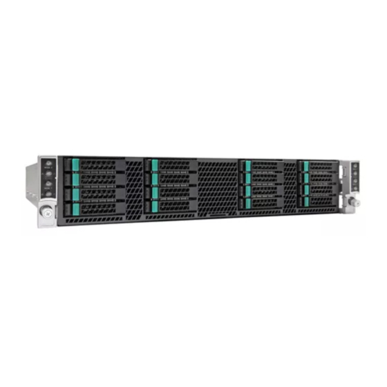
Server System Features 1 Server System Features ® This chapter briefly describes the main features of the Intel Server Chassis H2000 family. This includes illustrations of the products, a list of the server system features, and diagrams showing the location of important components and connections on the server systems. -
Page 14: Server Chassis Parts
Quick Reference Label provided on the inside of the chassis cover to assist in identifying components. The H2000 family is supporting 4 compute nodes in the chassis. The whole system view is as below (with top cover removed). -
Page 15: Figure 3. Front View Of Intel
The Compute Node in the chassis has dedicated numbering by position. ® Figure 5. Rear View of Intel Server Chassis H2000 with Power Supply Unit Each Compute Node has dedicated Hard Disk Drive array based on backplane controller design. Below are schemes for HDD array in correspondent to Compute Node. -
Page 16: Front Panel
Server System Features ® Figure 7. HDD array scheme on Intel Server Chassis H2216xx Front Panel The system contains two sets of control panels on left and right rack handles. Each control panel contains two sets of control buttons and LEDs for each Compute Node. Following is the scheme of control panel. -
Page 17: Hot-Swap Sas/Sata Backplane
2x40 pin Bridge Board connector for Node 1 20-pin Front Panel cable connector for Node 1, 3 2Blade Compute Node Power connector for Node 1 2x9 pin Power supply input connector 2x9 pin Power supply input connector ® Intel Server Chassis H2000 Family Service Guide... -
Page 18: Figure 11. 12 X 3.5-Inch Hard Drive Backplane Components (Rear View)
20-pin Front Panel cable connector for Node 1, 3 2Blade Compute Node Power connector for Node 1 2x9 pin Power supply input connector 2x9 pin Power supply input connector 2x40 pin Bridge Board connector for Node 2 ® Intel Server Chassis H2000 Family Service Guide... -
Page 19: Dummy Tray Cover
The Dummy tray cover is shipped together with chassis. It must be removed before installing computing node tray, or it must be restored if the compute node tray is empty. Figure 14. Dummy Tray Cover ® Intel Server Chassis H2000 Family Service Guide... -
Page 20: Hardware Installations And Upgrades
All references to left, right, front, top, and bottom assume the reader is facing the front of the chassis as it would be positioned for normal operation. ® Note: The Intel Server Chassis H2000 is shown for illustration purpose. Server components with the product family are identical. ® Intel... -
Page 21: Removing And Installing The Front Bezel
1. Lock the right end of the front bezel to the rack handle (see letter A). 2. Rotate the front bezel clockwise till the left end clicks into place (see letter B). 3. Lock the bezel if needed. Figure 16. Installing the Front Bezel ® Intel Server System H2000JF Family Service Guide... -
Page 22: Removing And Installing The Chassis Top Cover
Place system cover onto the chassis and slide forward to engage recessed edge at front of cover (see letter A). Rotate the front end of top cover down to position and fix screws (see letter B). ® Intel Server System H2000JF Family Service Guide... -
Page 23: Removing And Installing The Compute Node Tray
Each Compute Node tray is identical in the chassis. They are designed for either “cold” or “hot” swappable. The Node Tray can only be plugged from rear chassis. Installing the Node Tray 1. Remove the dummy tray cover. Figure 19. Removing Dummy Tray Cover ® Intel Server System H2000JF Family Service Guide... -
Page 24: Removing The Node Tray
Removing the Node Tray 1. Carefully push the latch in, on the left hand side of the Node Tray. 2. Pull the handle with the Node Tray while still pressing the latch. ® Intel Server System H2000JF Family Service Guide... -
Page 25: Removing And Installing The Redundant Power Supply Unit
Caution: Installing two Power Supply Units with different wattage ratings in a system is not supported. Doing so will not provide Power Supply Redundancy and will result in multiple errors being logged by the system. ® Intel Server System H2000JF Family Service Guide... -
Page 26: Removing The Power Supply Unit
Figure 24. Installing the PSU Installing and Removing Hot-swap Hard Drive Caution: If you don't install all drives, empty drive bays must be occupied by carriers with plastic drive blank provided to maintain proper system cooling. ® Intel Server System H2000JF Family Service Guide... -
Page 27: Installing A Hard Disk Drive Into 3.5" Hard Drive Carrier
Installing a Hard Disk Drive into 2.5" Hard Drive Carrier Remove the four screws securing the plastic drive blank from the 2.5" HDD carrier and install the 2.5" HDD with screws shown in below drawing. ® Intel Server System H2000JF Family Service Guide... -
Page 28: Installing And Removing The 2.5" Backplane Board
Figure 28. Installing Hard Disk Drive – Inserting 2.5" HDD assembly Installing and Removing the 2.5" Backplane Board Removing the 2.5" Backplane board 1. Disconnect all cables from the backplane board. 2. Remove power cable protective cover. ® Intel Server System H2000JF Family Service Guide... -
Page 29: Figure 29. Removing Power Cable Protective Cover
3. Remove the four screws to release the backplane board from chassis. 4. Straightly lift up the backplane board to remove from the chassis holder. Figure 30. Removing the 2.5" backplane board ® Intel Server System H2000JF Family Service Guide... -
Page 30: Installing The 2.5" Backplane Board
1. Place the backplane board into the clamps on chassis base. Figure 31. Align the backplane to the clamps on the chassis base 2. Secure the backplane board with four screws (see letter B). Figure 32. Installing the 2.5" backplane board ® Intel Server System H2000JF Family Service Guide... -
Page 31: Installing And Removing The 3.5" Backplane Board
Figure 33. Installing power cable protective cover Installing and Removing the 3.5" Backplane Board Removing the 3.5" Backplane board 1. Disconnect all cables from the backplane board. 2. Remove power cable protective cover. ® Intel Server System H2000JF Family Service Guide... -
Page 32: Figure 34. Removing Power Cable Protective Cover
3. Remove the three screws to release the backplane board from chassis. 4. Straightly lift up the backplane board to remove from the chassis holder. Figure 35. Removing the 2.5" backplane board ® Intel Server System H2000JF Family Service Guide... -
Page 33: Installing The Server Board
1. Place the backplane board into the clamps on chassis base. Figure 36. Align the backplane to the clamps on the chassis base 2. Secure the backplane board with three screws (see letter B). Figure 37. Installing the 2.5" backplane board ® Intel Server System H2000JF Family Service Guide... -
Page 34: Installing And Removing The Power Distribution Board
1. Remove top cover and power supply units from chassis. 2. Remove power cables and PMBus* cable between PDB and backplane. 3. Release the four screws of upper PDB board and remove it. ® Intel Server System H2000JF Family Service Guide... -
Page 35: Figure 39. Removing The Upper Pdb
Hardware Installations and Upgrades Figure 39. Removing the upper PDB 4. Release the four screws of lower PDB board and remove it. Figure 40. Removing the lower PDB ® Intel Server System H2000JF Family Service Guide... -
Page 36: Installing The Pdb
2. Install the lower PDB first and secure with four screws. Figure 41. Installing the lower PDB 3. Connect the power cables and PMBus* cable to lower PDB. 4. Install the upper PDB and secure with four screws. ® Intel Server System H2000JF Family Service Guide... -
Page 37: Replacing The Front Control Panel Board
Replacing the Front Control Panel board Removing the Front Control Panel 1. Loosen and remove four screws on the back of handle. Be careful of the control panel cable on the back. ® Intel Server System H2000JF Family Service Guide... -
Page 38: Figure 43. Removing Fp Assembly From Rack Handle
2. Disconnect the cable from the control panel board. Figure 44. Disconnecting Control Panel Cable 3. Loosen and remove two screws from back of control panel board, so the board can be removed out. ® Intel Server System H2000JF Family Service Guide... -
Page 39: Installing Front Control Panel Board
Hardware Installations and Upgrades Figure 45. Removing Control Panel Board Installing Front Control Panel Board 1. Install front control panel board to panel shell. ® Intel Server System H2000JF Family Service Guide... -
Page 40: Figure 46. Installing Control Panel Board
Hardware Installations and Upgrades Figure 46. Installing Control Panel Board 2. Connect cable to front panel board. Figure 47. Connecting Cable to Front Panel Board ® Intel Server System H2000JF Family Service Guide... -
Page 41: Rack Mounting The Chassis
3. Install front control panel assembly to chassis handle. Figure 48. Installing Control Panel Assembly to Rack Handle Rack Mounting the Chassis ® Intel AXXELVRAIL Rail Kit ® Intel AXXELVRAIL is a half extension value rail kit, which is bundled with H2000JF chassis. -
Page 42: Mounting The Chassis To Rack
Hardware Installations and Upgrades Mounting the Chassis to Rack ® The slide rail kit, which is bundled with Intel Server System H2000JF family is packed in the same shipping box together with the chassis. Based on the chassis design, the inner member of the rail is actually at the down side of the chassis. -
Page 43: Figure 51. Installing Slides To Rack
Hardware Installations and Upgrades 2. Install slides to rack. Figure 51. Installing Slides to Rack 3. Install inner members to chassis. Figure 52. Installing Inner Member to Chassis 4. Install chassis to fixed slides. ® Intel Server System H2000JF Family Service Guide... -
Page 44: Removing The Chassis From Rack
Figure 53. Installing the Chassis to Rack Removing the Chassis from Rack Following the below steps to remove the chassis from Rack. 1. Extend slides. Figure 54. Extending Slides before Chassis Removal 2. Remove Inner Member from Chassis. ® Intel Server System H2000JF Family Service Guide... -
Page 45: Figure 55. Removing The Chassis From Rack
Hardware Installations and Upgrades Figure 55. Removing the Chassis from Rack ® Intel Server System H2000JF Family Service Guide... -
Page 46: Appendix A: Technical Reference
In typical office ambient temperature. (23 +/- 2 degrees C). Shock, operating Half sine, 2 g peak, 11 milliseconds Shock, unpackaged Trapezoidal, 25 g, velocity change 205 inches/second (80 lbs to < 100 lbs) ® Intel Server System H2000JF Family Service Guide... - Page 47 Vibration, unpackaged 5 Hz to 500 Hz, 2.20 g RMS random ® +/-12 KV except I/O port +/- 8 KV per Intel Environmental Test Specification. System Cooling Requirement in BTU/Hr 1200 Watt Max – 4095 BTU/hour 1600 Watt Max – 5459 BTU/hour ®...
-
Page 48: Appendix B: Regulatory And Compliance Information
Appendix B: Regulatory and Compliance Information Appendix B: Regulatory and Compliance Information Please refer to the Server Products Regulatory and Safety document for the product regulatory compliance reference. The document can be downloaded from http://www.intel.com/p/en_US/support/server/. ® Intel Server System H2000JF Family Service Guide... -
Page 49: Appendix C: Getting Help
— A searchable knowledgebase to search for product information throughout the support site ® If you are still unable to obtain a solution to your issue, send an email to Intel ’s technical support center using the online form available at http://supportmail.intel.com/scripts-emf/welcome.aspx. -
Page 50: Appendix D: Intel Server Issue Report Form
® Appendix D: Intel Server Issue Report Form ® Appendix D: Intel Server Issue Report Form Issue Report Form (Rev 3.6) Note: Filling out this form completely is required for any escalation. Customer Contact Information: Customer Support Case#: ® Intel... - Page 51 ® Appendix D: Intel Server Issue Report Form Processor information: Type Speed Spec Thermal Solution Processor 1 Processor 2 Processor 3 Processor 4 Thermal solution (Heat sink) examples: (1U, Passive w/air ducting, Active w/fan, and so on) Memory: ® Manufacturer...
- Page 52 ® Appendix D: Intel Server Issue Report Form Description/Use Manufacturer Model Firmware Storage Devices (Example: SCSI, SATA, SAS, USB, Tape, and so on): Manufacturer Model Type Size Firmware In Hot Swap Bay? Operating System Information (Example: RedHat* Enterprise Linux, Microsoft Windows...
- Page 53 ® Appendix D: Intel Server Issue Report Form Detailed description of issue: Troubleshooting tried: Steps to replicate the issue: ® Intel Server System H2000JF Family Service Guide...
- Page 54 Server Issue Report Form Issue impact statements: ® Do you have any potential Intel system, or component purchases that this issue is holding up? If yes, please provide a brief description below. Do you have systems already purchased that are not being delivered to your customers because of this issue? If yes, please provide a brief description below.
Need help?
Do you have a question about the H2000 Series and is the answer not in the manual?
Questions and answers