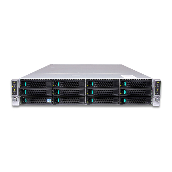
Intel H2000G series Service Manual
Server chassis
Hide thumbs
Also See for H2000G series:
- Configuration manual (32 pages) ,
- Configuration manual (34 pages) ,
- Service manual (35 pages)
Table of Contents
Advertisement
Quick Links
Download this manual
See also:
Configuration Manual
Advertisement
Table of Contents

Related Manuals for Intel H2000G series


Summary of Contents for Intel H2000G series
- Page 1 Intel® Server Chassis H2000G Product Family Service Guide Instruction on installation and removal of subassemblies. Rev 2.2 January 2017 Intel® Server Products and Solutions...
- Page 2 <Blank page>...
- Page 3 Intel® Server Chassis H2000G Product Family Service Guide Document Revision History Date Revision Changes January 2015 Initial release. December 2015 Applied new format. May 2016 Added H2224XXKR2 and H2224XXLR2. January 2017 2.11 Added “Caution” safety legend. January 2017 Applied new format.
- Page 4 Learn more at Intel.com, or from the OEM or retailer. You may not use or facilitate the use of this document in connection with any infringement or other legal analysis concerning Intel products described herein. You agree to grant Intel a non-exclusive, royalty-free license to any patent claim thereafter drafted which includes subject matter disclosed herein.
-
Page 5: Safety Information
Consignes de sécurité Lisez attention toutes les consignes de sécurité et les mises en garde indiquées dans ce document avant de suivre toute instruction. Consultez Intel Server Boards and Server Chassis Safety Information sur le site http://www.intel.com/content/www/us/en/support/boards-and-kits/000007675.html. Instrucciones de seguridad importantes Lea todas las declaraciones de seguridad y precaución de este documento antes de realizar cualquiera de las... - Page 6 Caution: Slide/rail mounted equipment is not to be used as a shelf or a work space. Intel warranties that this product will perform to its published specifications. However, all computer systems are inherently subject to unpredictable system behavior under various environmental and other conditions.
-
Page 7: Table Of Contents
Intel® Server Chassis H2000G Product Family Service Guide Table of Contents 1. Preface ..................................11 About this Document ..............................11 Document Organization .............................. 11 Additional Information and Software ........................11 2. Product Features ..............................12 Product Feature Overview ............................13 Server Chassis Components ............................ - Page 8 Intel® Server Chassis H2000G Product Family Service Guide Replacing the 16 x 2.5" Backplane Board ......................33 3.8.1 Removing the 16 x 2.5" Backplane Board ......................33 3.8.2 Installing the 16 x 2.5" Backplane Board ......................34 Replacing the SAS/PCIe* SFF Combo 24 x 2.5" Hot Swap Backplane ............. 35 3.9.1...
- Page 9 Figure 8. Drive array scheme on the Intel® Server Chassis H2312XXKR2 ................. 15 Figure 9. Drive array scheme on the Intel® Server Chassis H2216XXKR2 ................. 15 Figure 10. Drive array scheme on the Intel® Server Chassis H2224XXKR2/ H2224XXLR2 ........16 Figure 11. Location of front panel and LEDs ..........................16 Figure 12.
- Page 10 Intel® Server Chassis H2000G Product Family Service Guide Figure 41. Installing a 2.5” HDD or SSD – removing the drive blank ................... 30 Figure 42. Installing a 2.5” HDD or SSD – inserting the 2.5” HDD or SSD ................. 30 Figure 43.
-
Page 11: Preface
Intel® Server Chassis H2000G product family. This document provides a brief overview of the features of the Intel® Server Chassis H2000G product family, a list of accessories or other components that may be needed, troubleshooting information, and instructions on how to add and replace the components on the Intel®... -
Page 12: Product Features
Intel® Server Chassis H2000G Product Family Service Guide Product Features This chapter briefly describes the main features of the Intel® Server Chassis H2000G product family. This includes illustrations of the product, a list of the product features, and diagrams showing the location of important components and connections. -
Page 13: Product Feature Overview
The Intel® Server Chassis H2000G product family supports four compute modules in the chassis. Figure 3 and Figure 4 show the whole chassis view with the power distribution module cover removed. -
Page 14: Figure 3. Server Chassis Components (12 X 3.5" Drive Bay)
Intel® Server Chassis H2000G Product Family Service Guide – Front control panels – Power supply modules – Drive bays – Hot swap backplane (attached to – Power distribution modules the drive cage) Figure 3. Server chassis components (12 x 3.5” drive bay) –... -
Page 15: Drive Bays
Each compute module has a dedicated drive array based on the backplane controller design. Figure 8, Figure 9, and Figure 10 show the schemes for the drive arrays corresponding to the compute modules. Figure 8. Drive array scheme on the Intel® Server Chassis H2312XXKR2 Figure 9. Drive array scheme on the Intel® Server Chassis H2216XXKR2... -
Page 16: Front Control Panel
Intel® Server Chassis H2000G Product Family Service Guide Figure 10. Drive array scheme on the Intel® Server Chassis H2224XXKR2/ H2224XXLR2 Front Control Panel The server chassis contains two sets of control panels on the left and right rack handles. Each control panel contains two sets of control buttons and LEDs for each compute module. -
Page 17: Backplane Interposer Board
Intel® Server Chassis H2000G Product Family Service Guide Backplane Interposer Board The backplane interposer board (BIB) is only used in 24 x 2.5” drive chassis as the interposer between the backplane and the power docking board to connect the power and miscellaneous signals from the backplane to the compute modules. -
Page 18: Hot-Swap Sas/Sata Backplane
Intel® Server Chassis H2000G Product Family Service Guide Hot-Swap SAS/SATA Backplane The hot-swap SAS/SATA backplane serves as an interface between the mother board and the drives. The following diagrams show the location for each connector found on the backplane. 2.7.1 3.5"... -
Page 19: 16 X 2.5" Hot-Swap Backplane
Intel® Server Chassis H2000G Product Family Service Guide 2.7.2 16 x 2.5" Hot-Swap Backplane – SATA/SAS connectors for node 1 – SATA/SAS connectors for node 3 – SATA/SAS connectors for node 2 – SATA/SAS connectors for node 4 Figure 18. 16 x 2.5" backplane components (front view) –... -
Page 20: Sas/Pcie* Sff Combo 24 X 2.5" Hot Swap Backplane
Intel® Server Chassis H2000G Product Family Service Guide 2.7.3 SAS/PCIe* SFF Combo 24 x 2.5" Hot Swap Backplane – SAS 0-3 SFF-8680 connectors (compute module 1) – SAS 4-5/PCIe* SFF 0-1 SFF 8639 connectors (compute module 1) – SAS 6-9 SFF-8680 connectors (compute module 3) –... -
Page 21: Dummy Tray Cover
Intel® Server Chassis H2000G Product Family Service Guide Dummy Tray Cover The dummy tray cover is shipped together with the chassis. It must be removed before installing the compute module, or it must be restored if the compute module is not to be installed. -
Page 22: Hardware Installations And Upgrades
Intel® Server Chassis H2000G Product Family Service Guide Hardware Installations and Upgrades Before Beginning Before working with the server product, pay close attention to the Safety Information at the beginning of this document. Warning: The transparent plastic protective films (if any) on the chassis top surface must be removed for proper system cooling. -
Page 23: Removing The Front Bezel
Intel® Server Chassis H2000G Product Family Service Guide To remove a snap-on badge from the bezel, squeeze the hooks at the rear of the snap-on badge to release it (A) and remove the snap-on badge from the bezel (B) as pictured in Figure 24. -
Page 24: Installing The Front Bezel
Intel® Server Chassis H2000G Product Family Service Guide 3.2.3 Installing the Front Bezel Note: Before installing the front bezel, the rack handles must be installed. To install the front bezel, lock the right side of the bezel to the rack handle (A) and press the left side of the bezel towards the chassis until it clicks into place (B) as pictured in Figure 26. -
Page 25: Installing The Power Distribution Module Cover
Intel® Server Chassis H2000G Product Family Service Guide 3.3.2 Installing the Power Distribution Module Cover To install the power distribution module cover, refer to Figure 28. 1. Place the cover onto the chassis and slide forward until the front edge of the cover is pressed against the back edge of the front drive bay (A). -
Page 26: Removing The Compute Module
Intel® Server Chassis H2000G Product Family Service Guide 3. While pressing the latch, push the compute module along the chassis rail until the latch locks in position (Figure 30). Figure 30. Installing the compute module 3.4.2 Removing the Compute Module To remove the compute module: 1. -
Page 27: Removing And Installing The Redundant Power Supply Unit
Intel® Server Chassis H2000G Product Family Service Guide Removing and Installing the Redundant Power Supply Unit The server chassis is equipped with two redundant power supply units. Each of them can be hot-swappable. Caution: Installing two power supply units with different wattage ratings in a server chassis is not supported. -
Page 28: Installing A 3.5" Hard Disk Drive (Hdd)
Intel® Server Chassis H2000G Product Family Service Guide 3.6.1 Installing a 3.5” Hard Disk Drive (HDD) 1. Remove the drive carrier from the chassis by pressing the green button and pulling open the lever (A) and pull the carrier out of the drive bay (B) as pictured in Figure 35. -
Page 29: Installing A 2.5" Solid State Drive (Ssd) Into A 3.5" Carrier
Intel® Server Chassis H2000G Product Family Service Guide 3.6.2 Installing a 2.5” Solid State Drive (SSD) into a 3.5” Carrier The provided 3.5” drive blank can also be used as a 2.5” device bracket, allowing a 2.5” SSD to be installed into a 3.5”... -
Page 30: Installing A 2.5" Storage Device (Hdd Or Ssd)
Intel® Server Chassis H2000G Product Family Service Guide 3.6.3 Installing a 2.5” Storage Device (HDD or SSD) 1. Remove the drive carrier from the chassis by pressing the green button, opening the lever (A) and pulling the carrier out of the drive bay (B) as pictured in Figure 40. -
Page 31: Replacing The 12 X 2.5" Backplane Board
Intel® Server Chassis H2000G Product Family Service Guide 4. With the lever open, insert the carrier assembly into the chassis (F) and push in the lever to lock it into place (G) as pictured in Figure 43. Figure 43. Installing a 2.5” HDD or SSD – inserting the carrier assembly Replacing the 12 x 2.5"... -
Page 32: Installing The 2.5" Backplane Board
Intel® Server Chassis H2000G Product Family Service Guide 5. Remove the screws from the backplane board (E) and detach the backplane board from the drive cage (F) as pictured in Figure 45. Figure 45. Removing the 12 x 2.5" backplane board from the drive cage 3.7.2... -
Page 33: Replacing The 16 X 2.5" Backplane Board
Intel® Server Chassis H2000G Product Family Service Guide 2. Install the drive cage to the chassis (C) and fix the drive cage with the screws (D, E and F) as pictured in Figure 47. Figure 47. Installing the drive cage to the chassis 3. -
Page 34: Installing The 16 X 2.5" Backplane Board
Intel® Server Chassis H2000G Product Family Service Guide 5. Remove the screws from the backplane board (E) and detach the backplane board from the drive cage (F) as pictured in Figure 49. Figure 49. Removing the 16 x 2.5" backplane board from the drive cage 3.8.2... -
Page 35: Replacing The Sas/Pcie* Sff Combo 24 X 2.5" Hot Swap Backplane
Intel® Server Chassis H2000G Product Family Service Guide 2. Install the drive cage to the chassis (C) and fix the drive cage with the screws (D, E and F) as pictured in Figure 51. Figure 51. Installing the drive cage to the chassis 3. -
Page 36: Installing The Sas/Pcie* Sff Combo 24 X 2.5" Hot Swap Backplane
Intel® Server Chassis H2000G Product Family Service Guide 6. Disconnect the front panel cable from the backplane interposer board. 7. Remove the five screws from the backplane board (E), remove the screw and the bracket from the bottom of the drive cage (F), and detach the backplane board from the drive cage (G) as pictured in Figure Figure 53. -
Page 37: 3.10 Removing And Installing The Power Distribution Module
Intel® Server Chassis H2000G Product Family Service Guide 2. Install the drive cage to the chassis (D) and fix the drive cage with the screws (E, F, and G) as pictured in Figure 55. Figure 55. Installing the drive cage to the chassis 3. -
Page 38: Installing The Power Distribution Module
Intel® Server Chassis H2000G Product Family Service Guide 3.10.2 Installing the Power Distribution Module 1. Slide in the power distribution module (A) and fix the module with the two screws (B) as pictured in Figure 57. Figure 57. Installing the power distribution module 2. -
Page 39: Installing The Power Interposer Board
Intel® Server Chassis H2000G Product Family Service Guide 3.11.2 Installing the Power Interposer Board Place the power interposer board into the compute module (A), rotate the bracket counterclockwise all the way (B), and tighten the screw (C) as pictured in Figure 59. -
Page 40: Installing The Front Control Panel Board
Intel® Server Chassis H2000G Product Family Service Guide 3. Remove the two screws from the back of the front control panel board (C) and remove the board as pictured in Figure 62. Figure 62. Removing the front control panel board 3.12.2... -
Page 41: Figure 64. Installing The Front Control Panel Assembly To The Rack Handle
Intel® Server Chassis H2000G Product Family Service Guide 3. Install the front control panel assembly to the rack handle with the four screws (C) as pictured in Figure Figure 65. Installing the front control panel assembly to the rack handle... -
Page 42: Appendix A. Technical Reference
System Cooling Requirement 2130 W maximum – 7268 BTU/hour Disclaimer Note: Intel ensures the unpackaged server board and system meet the shock requirement mentioned above through its own chassis development and system configuration. It is the responsibility of the system integrator to determine the proper shock level of the board and system if the system integrator chooses different system configuration or different chassis. -
Page 43: Appendix B. Regulatory And Compliance Information
Intel® Server Chassis H2000G Product Family Service Guide Appendix B. Regulatory and Compliance Information Refer to the Server Products Regulatory and Safety document for the product regulatory compliance reference. The document can be downloaded from http://www.intel.com/content/www/us/en/support/boards-and-kits/000007675.html. -
Page 44: Appendix C. Getting Help
A searchable knowledgebase to find for product information throughout the support site. 2. If a solution cannot be found at Intel’s support site, send an email to Intel’s technical support center using the online form available at http://www.intel.com/support/feedback.htm?group=server. 3. Lastly, contact an Intel support representative using one of the support phone numbers available at http://www.intel.com/support/feedback.htm?group=server...
Need help?
Do you have a question about the H2000G series and is the answer not in the manual?
Questions and answers