Intel P4304XXMFEN2 Service Manual
Server chassis
Hide thumbs
Also See for P4304XXMFEN2:
- Service manual (194 pages) ,
- Spares/accessories list and configuration manual (54 pages)

Related Manuals for Intel P4304XXMFEN2


Summary of Contents for Intel P4304XXMFEN2
- Page 1 Intel® Server Chassis P4304XXMFEN2/P4304XXMUXX Product Family System Integration and Service Guide A Guide for Technically Qualified Assemblers of Intel identified Subassemblies/Products Revision 1.3 May 2017...
- Page 2 Information in this document is provided in connection with Intel® products. No license, express or implied, by estoppel or otherwise, to any intellectual property rights is granted by this document. Except as provided in Intel's Terms and Conditions of Sale for such...
- Page 3 Consignes de sécurité Lisez attention toutes les consignes de sécurité et les mises en garde indiquées dans ce document avant de suivre toute instruction. Consultez Intel Server Boards and Server Chassis Safety Information sur le site http://www.intel.com/support/motherboards/server/sb/cs-010770.htm. Instrucciones de seguridad importantes Lea todas las declaraciones de seguridad y precaución de este documento antes de realizar cualquiera...
- Page 4 Intel ® Server Chassis P4304XXMFEN2/P4304XXMUXX Product Family System Integration and Service Guide Warnings Heed safety instructions: Before working with your server product, whether you are using this guide or any other resource as a reference, pay close attention to the safety instructions. You must adhere to the assembly instructions in this guide to ensure and maintain compliance with existing product certifications and approvals.
- Page 5 Setup screens. System Service Chapter 5 – System Features Overview – provides a high level overview of the Intel® Server Board S2600CW and Intel® Server Chassis P4304XXMFEN2/P4304XXMUXX product family. In this chapter, you will find a list of the server chassis features and illustrations identifying the major system components.
- Page 6 Intel ® Server Chassis P4304XXMFEN2/P4304XXMUXX Product Family System Integration and Service Guide Additional Information and Software For additional information about this family of products or any of their supported accessories, refer to the following resources available at http://www.intel.com/support. Table 1. Server Chassis References...
-
Page 7: Table Of Contents
Intel ® Server Chassis P4304XXMFEN2/P4304XXMUXX Product Family System Integration and Service Guide Table of Contents 1. Server Building Block System Integration ......................1 Intel® Server Chassis Identification ..........................2 Server Building Block Installation ..........................3 1.2.1 Removing the Chassis Side Cover ..........................3 1.2.2... - Page 8 Connecting the Plastic Battery Holder to the Chassis ..................66 3.4.4 Removing the Intel® RAID Smart Battery ......................67 Intel® Remote Management Module 4 Lite Key – Installation / Removal ..........68 3.5.1 Intel® RMM4 Lite Key Installation ..........................68 3.5.2...
- Page 9 Intel ® Server Chassis P4304XXMFEN2/P4304XXMUXX Product Family System Integration and Service Guide Appendix A: Getting Help..............................82 Appendix B: POST Code Diagnostic LED Decoder Table ..................83 Appendix C: POST Code Errors ............................89...
- Page 10 Server Chassis P4304XXMFEN2/P4304XXMUXX Product Family System Integration and Service Guide List of Figures Figure 1. Intel® Server Chassis P4304XXMFEN2 – Fixed Power Supply ................2 Figure 2. Intel® Server Chassis P4304XXMUXX – Optional Redudant Power Supplies ..........2 Figure 3. Server Board Installation ............................... 5 Figure 4.
- Page 11 Intel ® Server Chassis P4304XXMFEN2/P4304XXMUXX Product Family System Integration and Service Guide Figure 39. Installing the RAID Card again ............................65 Figure 40. Align the tabs with battery holder ..........................66 Figure 41. Slide the battery holder ..............................67 Figure 42. Installing the Intel ®...
- Page 12 Intel ® Server Chassis P4304XXMFEN2/P4304XXMUXX Product Family System Integration and Service Guide List of Tables Table 1. Server Chassis References ..............................vi Table 2. BIOS Setup: Keyboard Command Bar ..........................71 Table 3. POST Progress Code LED Example ..........................84 Table 4.
-
Page 13: Server Building Block System Integration
1. Server Building Block System Integration Purpose This chapter provides instructions for the integration of the following Intel server building blocks: Intel® Server Chassis P4304XXMFEN2 + Intel® Server Board S2600CW family Intel® Server Chassis P4304XXMUXX + Intel® Server Board S2600CW family + Power Supply... -
Page 14: Intel® Server Chassis Identification
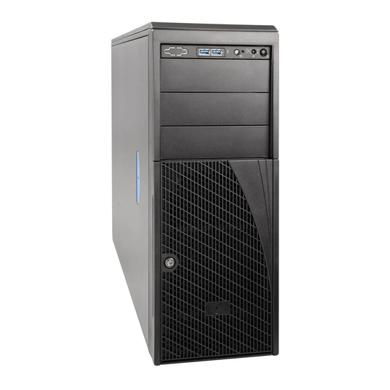
Intel ® Server Chassis P4304XXMFEN2/P4304XXMUXX Product Family System Integration and Service Guide 1.1 Intel® Server Chassis Identification Power Supply Serial-B Port (Optional) IO Connectors Kensington* Cable Lock Mounting Hole RMM4 NIC Port (Optional) Padlock Loop Add in PCI-e cards Power Connector RMM4 NIC Port (Optional) Figure 1. -
Page 15: Server Building Block Installation
Intel ® Server Chassis P4304XXMFEN2/P4304XXMUXX Product Family System Integration and Service Guide 1.2 Server Building Block Installation 1.2.1 Removing the Chassis Side Cover Loosen the two screws located on the back edge of the chassis side cover (see letter “A”). - Page 16 Intel ® Server Chassis P4304XXMFEN2/P4304XXMUXX Product Family System Integration and Service Guide...
-
Page 17: Server Board Installation
Intel ® Server Chassis P4304XXMFEN2/P4304XXMUXX Product Family System Integration and Service Guide 1.2.4 Server Board Installation Figure 3. Server Board Installation Note: Follow ESD precautions outlined at the beginning of this manual. Carefully move aside any cables that may be taped to the chassis base to clear the area for server board placement. -
Page 18: Power Supply Installation (Optional)
1.2.5 750W Power Supply Installation (Optional) Note: If the chassis model is P4304XXMFEN2, one 550W fixed power supply is already installed. If the chassis model is P4304XXMUXX, one or two separate power supplies need to be ordered separately and installed in the server chassis. The server chassis P4304XXMUXX supports 750W or 1600W redundant power supplies. - Page 19 Intel ® Server Chassis P4304XXMFEN2/P4304XXMUXX Product Family System Integration and Service Guide...
-
Page 20: Figure 5. Installing 1600W Power Supply
Intel ® Server Chassis P4304XXMFEN2/P4304XXMUXX Product Family System Integration and Service Guide Figure 5. Installing 1600W Power Supply... -
Page 21: Cable Routing And Connection
1.3.1 Routing the Cables 1. For P4304XXMFEN2, the power cables for HDD/ODD bays should be routed through the opening on the system fan bracket, close to the chassis side wall; for P4304XXMUXX, the power cables for HDD/ODD bays should be routed under the 5 system fan. -
Page 22: Figure 7. P4304Xxmuxx Cable Routing
Intel ® Server Chassis P4304XXMFEN2/P4304XXMUXX Product Family System Integration and Service Guide CPU1/2 power cable Main power cable SSD/HDD drive bay power cable (SAS/SATA) ODD drive bay power cable Front panel and USB cable ODD data cable SSD/HDD drive bay data cable... -
Page 23: Connecting The Power Cables To The Server Board
Intel ® Server Chassis P4304XXMFEN2/P4304XXMUXX Product Family System Integration and Service Guide 1.3.2 Connecting the Power Cables to the Server Board Connect the 2x12 pin cable connector to the server board close to the server edge (silkscreen labeled “MAIN_PWR”). Connect the 2x4 pin cable connector to the server board close to CPU1 (silkscreen labeled “CPU_1_PWR”). -
Page 24: Connecting The System Fan Cables To The Server Board
1.3.3 Connecting the System Fan Cables to the Server Board 1. For server chassis P4304XXMFEN2, connect the cables of the two system fans to the fan headers on the board (silkscreen labled “SYS_FAN_1” and “SYS_FAN_2”). 2. For server chassis P4304XXMUXX, connect the cables of the five system fans to the fan headers on the board (silkscreen labled “SYS_FAN_1”, “SYS_FAN_2”, “SYS_FAN_3”, “SYS_FAN_4”... -
Page 25: Connecting The Cables To The Front Panel
Intel ® Server Chassis P4304XXMFEN2/P4304XXMUXX Product Family System Integration and Service Guide 1.3.4 Connecting the Cables to the Front Panel 1. Connect the front panel cable to the 2x12 SSI compliant front panel connector on the server board edge (silkscreen labeled “SSI_FRONT_PANEL”). -
Page 26: Essential System Component Installation And Service
Intel ® Server Chassis P4304XXMFEN2/P4304XXMUXX Product Family System Integration and Service Guide 2. Essential System Component Installation and Service Purpose This chapter provides instructions for the installation and removal of essential system components including processors, memory, storage devices, and add-in cards. -
Page 27: Internal Cable Routing
DIMMs slots. 1. For P4304XXMFEN2, the power cables for HDD/ODD bays should be routed through the opening on the system fan bracket, close to the chassis side wall; for P4304XXMUXX, the power cables for HDD/ODD bays should be routed under the 5 system fan. -
Page 28: Figure 10. Internal Cable Routing
Intel ® Server Chassis P4304XXMFEN2/P4304XXMUXX Product Family System Integration and Service Guide CPU1/2 power cable Main power cable SSD/HDD drive bay power cable (SAS/SATA) ODD drive bay power cable Front panel and USB cable ODD data cable SSD/HDD drive bay data cable... -
Page 29: Chassis Side Cover Removal / Installation
Intel ® Server Chassis P4304XXMFEN2/P4304XXMUXX Product Family System Integration and Service Guide 2.2 Chassis Side Cover Removal / Installation 2.2.1 Chassis Side Cover Removal The server chassis must be operated with the chassis side cover in place to ensure proper cooling. The side cover must be removed to add or replace components inside of the chassis. -
Page 30: Chassis Side Cover Installation
Intel ® Server Chassis P4304XXMFEN2/P4304XXMUXX Product Family System Integration and Service Guide 2.2.2 Chassis Side Cover Installation 1. Place the chassis side cover onto the chassis and slide forward until the front edge of the cover is pressed up against the back edge of the front drive bay (see letter “A”). -
Page 31: Air Duct Removal / Installation
Intel ® Server Chassis P4304XXMFEN2/P4304XXMUXX Product Family System Integration and Service Guide 2.3 Air Duct Removal / Installation Always operate your server chassis with the air duct in place. The air duct is required for proper airflow within the server chassis. -
Page 32: System Fan Assembly Removal / Installation
Intel ® Server Chassis P4304XXMFEN2/P4304XXMUXX Product Family System Integration and Service Guide 2.4 System Fan Assembly Removal / Installation System fan assembly removal is required whenever routing cables inside the chassis from back to front or from front to back, or when server board replacement is necessary. - Page 33 ® Server Chassis P4304XXMFEN2/P4304XXMUXX Product Family System Integration and Service Guide To remove the fixed system fan (CPU fan or PCIe fan) from P4304XXMFEN2 1. Unplug the fan cable from the server board (see letter “A”). 2. Open the two latches on both sides of the system fan until the fan is full disengaged from the fan...
-
Page 34: System Fan Assembly Installation
Intel ® Server Chassis P4304XXMFEN2/P4304XXMUXX Product Family System Integration and Service Guide 2.4.2 System Fan Assembly Installation To install the hot-swap system fan on P4304XXMUXX Align the two guide pins on the fan with the openings located on the fan bracket. - Page 35 Intel ® Server Chassis P4304XXMFEN2/P4304XXMUXX Product Family System Integration and Service Guide To install the fixed system fan on P4304XXMFEN2 Route the fixed fan cable through the fan holder. Align the fixed fan with the fan holder, and press the fixed fan until it clicks and fits into place.
-
Page 36: Processor Installation / Removal
Intel ® Server Chassis P4304XXMFEN2/P4304XXMUXX Product Family System Integration and Service Guide 2.5 Processor Installation / Removal 2.5.1 Processor Heatsink(s) Removal Figure 13. Processor Heatsink Removal The heatsink is attached to the server board or processor socket with captive fasteners. Using a #2... -
Page 37: Processor Installation
Intel ® Server Chassis P4304XXMFEN2/P4304XXMUXX Product Family System Integration and Service Guide 2.5.2 Processor Installation Caution: Processor must be appropriate: You may damage the server board if you install a processor that is inappropriate for your server. For a web link to the list of compatible processor(s), see “Additional... -
Page 38: Figure 16. Processor Installation - Install The Processor
Intel ® Server Chassis P4304XXMFEN2/P4304XXMUXX Product Family System Integration and Service Guide 3. Install the Processor. Note: The underside of the processor has components that may damage the socket pins if installed improperly. The processor must align correctly with the socket opening before installation. DO NOT DROP the processor into the socket. -
Page 39: Figure 18. Processor Installation - Close The Load Plate
Intel ® Server Chassis P4304XXMFEN2/P4304XXMUXX Product Family System Integration and Service Guide 5. Close the Load Plate. Figure 18. Processor Installation – Close the Load Plate Carefully lower the load plate down over the processor. 6. Lock down the Load Plate. -
Page 40: Processor Heatsink Installation
Intel ® Server Chassis P4304XXMFEN2/P4304XXMUXX Product Family System Integration and Service Guide 2.5.3 Processor Heatsink Installation Figure 20. Processor Heatsink Installation 1. If present, remove the protective film covering the Thermal Interface Material on the bottom side of the heatsink (see letter “A”). -
Page 41: Memory Installation And Removal
Intel ® Server Chassis P4304XXMFEN2/P4304XXMUXX Product Family System Integration and Service Guide 2.6 Memory Installation and Removal 2.6.1 Memory Slot Population Requirements Note: Some system configurations may come with pre-installed DIMM blanks. DIMM blanks should only be removed when installing a DIMM in the same DIMM slot. Memory population rules apply when installing DIMMs. -
Page 42: Removing Memory
Intel ® Server Chassis P4304XXMFEN2/P4304XXMUXX Product Family System Integration and Service Guide 2.6.3 Removing Memory Figure 22. Removing Memory 1. Locate the DIMM sockets. Unlatch the retaining clips located on each end of the socket. The DIMM lifts from the socket (see letter “A”). -
Page 43: Storage Device Installation/Upgrade
Intel ® Server Chassis P4304XXMFEN2/P4304XXMUXX Product Family System Integration and Service Guide 2.7 Storage Device Installation/Upgrade The server chassis support several different storage device options. This section provides instruction for the installation and upgrade of front drive bay storage devices. Installation of other storage options available through accessory kits is provided in Chapter 3. - Page 44 Intel ® Server Chassis P4304XXMFEN2/P4304XXMUXX Product Family System Integration and Service Guide 8x2.5 Upgrade Option 8x2.5 NVMe Combo Upgrade Option 16x2.5 Upgrade Option The table below shows the the cables required for these storage drive options. Drive Count Configuration Cable Type...
-
Page 45: Removing The Front Bezel
Intel ® Server Chassis P4304XXMFEN2/P4304XXMUXX Product Family System Integration and Service Guide 2.7.1 Removing the Front Bezel Before accessing the storage device, the front bezel needs to be removed. 1. Remove the chassis side cover following the instruction in session “Chassis Side Cover Removal”. -
Page 46: Installing The Front Bezel
Intel ® Server Chassis P4304XXMFEN2/P4304XXMUXX Product Family System Integration and Service Guide 2.7.2 Installing the Front Bezel Fit the right edge of the bezel assembly against the right side of the chassis. Engage the plastic bezel hooks (see letter “A”) into the raised metal slots at the chassis edge. - Page 47 Intel ® Server Chassis P4304XXMFEN2/P4304XXMUXX Product Family System Integration and Service Guide Remove the fillers for 5.25” drive slots if required. Remove the cosmetic top board. Install the front panel module.
- Page 48 Intel ® Server Chassis P4304XXMFEN2/P4304XXMUXX Product Family System Integration and Service Guide Install the 5.25” drive if required. Install the rack bezel frame. NOTE The rack bezel frame is different from the pedestal bezel frame.
- Page 49 Intel ® Server Chassis P4304XXMFEN2/P4304XXMUXX Product Family System Integration and Service Guide Install the rack mount handles. Install the rack bezel (optional).
- Page 50 Intel ® Server Chassis P4304XXMFEN2/P4304XXMUXX Product Family System Integration and Service Guide Lock the front bezel key.
-
Page 51: Installing The Fixed Drive Storage
Server Chassis P4304XXMFEN2/P4304XXMUXX Product Family System Integration and Service Guide 2.7.4 Installing the Fixed Drive Storage The server chassis P4304XXMFEN2 and P4304XXMUXX support four 3.5” fixed drive trays with their default configuration. To install a fixed drive: Remove the chassis side cover following instructions in section “Chassis Side Cover Removal”. - Page 52 Intel ® Server Chassis P4304XXMFEN2/P4304XXMUXX Product Family System Integration and Service Guide Release the fixed drive tray by pressing the latches on both sides of the tray, and pull the drive tray until it is fully removed from the chassis.
- Page 53 Intel ® Server Chassis P4304XXMFEN2/P4304XXMUXX Product Family System Integration and Service Guide Slide the fixed drive tray back into the chassis until it clicks into place. Install the EMI cover to the chassis front.
- Page 54 Intel ® Server Chassis P4304XXMFEN2/P4304XXMUXX Product Family System Integration and Service Guide Cable connection: On server board side, connect the miniSAS HD cable header to the onboard connector labeled as “sSATA_0-3” or “SATA_0-3”. On fixed drive side, connect the SATA power header and the 7-pin SATA cable header. A cable example is shown as below.
-
Page 55: Upgrading The Fixed Drive Storage To 4X3.5" Or 8X2.5" Hot-Swap Drive Bay Storage
Intel ® Server Chassis P4304XXMFEN2/P4304XXMUXX Product Family System Integration and Service Guide 2.7.5 Upgrading the Fixed Drive Storage to 4x3.5” or 8x2.5” Hot-swap Drive Bay Storage The server chassis support fixed drive storage by default; the optional 4x3.5” or 8x2.5” hot-swap drive bays and cables can be ordered separately and installed in the server chassis as upgrade options. - Page 56 Intel ® Server Chassis P4304XXMFEN2/P4304XXMUXX Product Family System Integration and Service Guide Install the EMI cover by aligning the latch on the EMI cover to the chassis front and slide down (see letter “A” and “B”). Slide the 4x3.5” or 8x2.5” hot-swap drive bay to the upper/right drive bay position.
- Page 57 Intel ® Server Chassis P4304XXMFEN2/P4304XXMUXX Product Family System Integration and Service Guide Cable connection: If using a 4x3.5 hot-swap drive tray, connect the miniSAS HD cable header to the server board connector labeled as “sSATA_0-3” or “SATA_0-3”. If using an 8x2.5 hot-swap drive tray, connect the miniSAS HD cable header to both “sSATA_0-3”...
-
Page 58: Upgrading The Fixed Drive Storage To 8X2.5" Pcie Ssd (Nvme) Combo Drive Bay Storage
Intel ® Server Chassis P4304XXMFEN2/P4304XXMUXX Product Family System Integration and Service Guide 2.7.6 Upgrading the Fixed Drive Storage to 8x2.5” PCIe SSD (NVMe) Combo Drive Bay Storage The installation of the 8x2.5” SAS/PCIe SSD (NVMe) combo drive bay involves serveral components: NVMe add-in card •... - Page 59 Intel ® Server Chassis P4304XXMFEN2/P4304XXMUXX Product Family System Integration and Service Guide 4. Connect the NVMe cables to the NVMe add-in card and the 8x2.5” SAS/PCIe SSD (NVMe) Combo backplane. The cables can be found in FUP8X25S3NVDK. 5. Connect the I2C cable from the mother board HSBP_I2C header to the backplane I2C_IN (SMBus-in) header.
- Page 60 Intel ® Server Chassis P4304XXMFEN2/P4304XXMUXX Product Family System Integration and Service Guide Label Description SMBus-Out (I2C OUT) cable connector for multi-backplane support SATA/SAS Ports 4-7 Mini-SAS HD cable connector PCIe SSD Drive #3 Mini-SAS HD cable connector PCIe SSD Drive #2 Mini-SAS HD cable connector...
- Page 61 Intel ® Server Chassis P4304XXMFEN2/P4304XXMUXX Product Family System Integration and Service Guide The cables used to connect the NVMe add-in card to the 8x2.5” Combo backplane (PCIe SSD Drive #0~3 Mini-SAS HD cable connector) is shown as below. The backplane connects to the left side of the cable;...
-
Page 62: Upgrading The Fixed Drive Storage To 8X3.5" Hot-Swap Drive Bay Storage
Intel ® Server Chassis P4304XXMFEN2/P4304XXMUXX Product Family System Integration and Service Guide 2.7.7 Upgrading the Fixed Drive Storage to 8x3.5” Hot-swap Drive Bay Storage The server chassis can support two 4x3.5” hot-swap drive bays as an upgrade option from fixed drive storage. - Page 63 Intel ® Server Chassis P4304XXMFEN2/P4304XXMUXX Product Family System Integration and Service Guide On each backplane, connect one miniSAS HD cable to the connector labled as “HDD_0-3”. Connect the “HSBP_I2C” header on the server board to the “I2C_IN” header on the first backplane. Connect the “I2C_OUT”...
-
Page 64: Upgrading The Fixed Drive Storage To 16X2.5" Hot-Swap Drive Bay Storage
Intel ® Server Chassis P4304XXMFEN2/P4304XXMUXX Product Family System Integration and Service Guide 2.7.8 Upgrading the Fixed Drive Storage to 16x2.5” Hot-swap Drive Bay Storage The server chassis can support two 8x3.5” hot-swap drive bays as an upgrade option from fixed drive storage. - Page 65 Intel ® Server Chassis P4304XXMFEN2/P4304XXMUXX Product Family System Integration and Service Guide Connect the other end of the miniSAS HD cables to the backplane mini SAS HD connectors. Connect the “HSBP_I2C” header on the server board to the “I2C_IN” header on the first backplane. Connect the “I2C_OUT”...
-
Page 66: X 3.5" Front Drive Bay Storage
Intel ® Server Chassis P4304XXMFEN2/P4304XXMUXX Product Family System Integration and Service Guide 2.7.9 4 x 3.5” Front Drive Bay Storage 2.7.9.1 3.5” Drive Carrier Extraction Figure 23. Installing Hot-swap Storage Devices – 3.5” Carrier Extraction 1. Remove the drive carrier from the chassis by pressing the green button and pulling open the lever (see letter “A”). -
Page 67: Figure 25. 3.5" Hard Disk Drive Installation - Mounting The Drive To The Carrier
Intel ® Server Chassis P4304XXMFEN2/P4304XXMUXX Product Family System Integration and Service Guide Figure 25. 3.5” Hard Disk Drive Installation – Mounting the Drive to the Carrier 3. Install the drive into the carrier. Verify the connector end of the drive is located towards the back of the carrier (see letter “D”). -
Page 68: Figure 27. Hard Disk Drive Installation - Inserting The 3.5" Hdd Assembly
Intel ® Server Chassis P4304XXMFEN2/P4304XXMUXX Product Family System Integration and Service Guide 2.7.9.4 3.5” Drive Carrier Insertion Figure 27. Hard Disk Drive Installation – Inserting the 3.5” HDD Assembly 1. With the lever open, insert the drive assembly into the drive bay (see letter “E”). -
Page 69: X 2.5" Front Drive Bay Storage
Intel ® Server Chassis P4304XXMFEN2/P4304XXMUXX Product Family System Integration and Service Guide 2.7.10 8 x 2.5” Front Drive Bay Storage 2.7.10.1 2.5” Drive Carrier Extraction Figure 28. Installing Hot-swap Storage Devices – 2.5” Carrier Extraction 1. Remove the drive carrier from the chassis by pressing the green button and pulling open the lever (see letter “A”). -
Page 70: Figure 30. 2.5" Storage Device Installation - Mounting The Drive To The Carrier
Intel ® Server Chassis P4304XXMFEN2/P4304XXMUXX Product Family System Integration and Service Guide Figure 30. 2.5” Storage Device Installation – Mounting the Drive to the Carrier 3. Install the storage device into the carrier. Verify the connector end of the drive is located towards the back of the carrier (see letter “E”). -
Page 71: Option And Accessory Kit Integration And Service
Intel ® Server Chassis P4304XXMFEN2/P4304XXMUXX Product Family System Integration and Service Guide 3. Option and Accessory Kit Integration and Service Purpose This chapter provides instructions for the integration of system components within a server chassis that has the server board and other system components pre-installed. It includes installation instructions for supported system options, and other available accessory option kits. -
Page 72: Optical Drive - Installation And Removal
Intel ® Server Chassis P4304XXMFEN2/P4304XXMUXX Product Family System Integration and Service Guide 3.1 Optical Drive – Installation and Removal This section provides installation and removal instructions for an optionally installed SATA optical drive for systems that support the option. 3.1.1 Optical Drive Installation Note: The optical drive is NOT hot-swappable. -
Page 73: Optical Drive Removal
Intel ® Server Chassis P4304XXMFEN2/P4304XXMUXX Product Family System Integration and Service Guide 3.1.2 Optical Drive Removal Note: The optical drive is NOT hot-swappable. Before removing or replacing the drive, you must first take the server out of service; turn off all peripheral devices connected to the system, turn off the system by pressing the power button, and unplugging the power cord from the system or wall outlet. -
Page 74: Esrt2 Raid5 Key - Installation / Removal
Intel ® Server Chassis P4304XXMFEN2/P4304XXMUXX Product Family System Integration and Service Guide 3.2 ESRT2 RAID5 Key – Installation / Removal 3.2.1 Installing the ESRT2 RAID 5 Key Figure 36. ESRT2 RAID 5 Key Location 1. Remove the ESRT2 RAID 5 Key from its packaging. -
Page 75: Lsi Imr Raid5 Key - Installation / Removal
Intel ® Server Chassis P4304XXMFEN2/P4304XXMUXX Product Family System Integration and Service Guide 3.3 LSI IMR RAID5 Key – Installation / Removal 3.3.1 Installing the LSI IMR RAID 5 Key Figure 37. IMR RAID 5 Key Location 1. Remove the LSI IMR RAID 5 Key from its packaging. -
Page 76: Intel® Raid Smart Battery Axxrsbbu9 - Installation / Removal
A battery backup unit (BBU) protects the integrity of the cached data on Intel® RAID Controllers by providing backup power if there is a complete AC power failure or a brief power outage. The Intel® RAID Smart Battery Backup Unit provides an inexpensive alternative to using an uninterruptible power supply (UPS) or it can act as a second level of fault tolerance when used with a UPS. -
Page 77: Figure 39. Installing The Raid Card Again
1. Remove the RAID Controller if it is already installed in the server system. 2. Ground yourself, and remove the Intel® RAID Smart Battery AXXRSBBU9 from the package. 3. Verify that the cache memory board is already installed on the supported RAID controller. -
Page 78: Connecting The Plastic Battery Holder To The Chassis
3.4.3 Connecting the Plastic Battery Holder to the Chassis The Intel® RAID Smart Battery AXXRSBBU9 is designed for easy attachment to either an Intel® pedestal or rack mount chassis. Note: If you are installing this component into a third-party chassis, you must first install an attachment mechanism, such as industrial-grade Velcro*. -
Page 79: Removing The Intel® Raid Smart Battery
Intel ® Server Chassis P4304XXMFEN2/P4304XXMUXX Product Family System Integration and Service Guide Figure 41. Slide the battery holder 3. Slide the plastic battery holder toward the front of the system until the tabs engage with the clips in the chassis 3.4.4... -
Page 80: Intel® Remote Management Module 4 Lite Key - Installation / Removal
1. Remove the Intel® RMM4 Lite key from its packaging. 2. Locate the Intel® RMM4 Lite connector on the server board between the first two PCIe slots. 3. Place the Intel® RMM4 Lite key over the connector and match the orientation of the key to that of the connector. -
Page 81: Trusted Platform Module (Tpm) Installation
Intel ® Server Chassis P4304XXMFEN2/P4304XXMUXX Product Family System Integration and Service Guide 3.6 Trusted Platform Module (TPM) Installation 1. Locate the TPM module connector on the server board near the first PCIe slot. 2. Install the stand-off to the server board mounting hole (see letter “A”). -
Page 82: System Software Updates And Configuration
For best operation and system reliability, it is highly recommended to update the system software stack to the latest available. The latest system software stack can be downloaded from Intel at the following Intel web site: http://downloadcenter.intel.com At a minimum, after the initial configuration, the system’s FRU and SDR data MUST be updated to... -
Page 83: Navigating The Bios Setup Utility
Intel ® Server Chassis P4304XXMFEN2/P4304XXMUXX Product Family System Integration and Service Guide 4.2.3 Navigating the BIOS Setup Utility The BIOS Setup Utility consists of several menu screens, each holding either informational fields and/or configurable system setup options. The bottom right portion of each menu screen provides a list of commands that are used to navigate through the Setup utility. - Page 84 Intel ® Server Chassis P4304XXMFEN2/P4304XXMUXX Product Family System Integration and Service Guide Option Description <F9> Setup Defaults Pressing the <F9> key causes the following to display: Load Optimized Defaults? If “Yes” is highlighted and <Enter> is pressed, all Setup fields are set to their default values.
-
Page 85: System Features Overview
The intent of this chapter is to provide service personnel a reference to locate and identify the features associated with the Intel® Server Board S2600CW and Intel® Server Chassis P4304XXMFEN2/P4304XXMUXX product family. Additional information for this product family can be obtained from the following Intel documents which can be downloaded from the following Intel web site: http://www.intel.com/support Intel®... -
Page 86: Front Drive Bay Options
Intel ® Server Chassis P4304XXMFEN2/P4304XXMUXX Product Family System Integration and Service Guide Figure 44. Intel® Server Chassis P4304XXMUXX Features Overview 5.1.1 Front Drive Bay Options Figure 45. No Front Drive Bay Configuration – Chassis-only Building Block... -
Page 87: Control Panel Features
Intel ® Server Chassis P4304XXMFEN2/P4304XXMUXX Product Family System Integration and Service Guide 5.1.2 Control Panel Features Reserved USB Connectors ID Button NMI Button System Reset Button System Power Button Figure 46. P4304XXMFEN2/P4304XXMUXX Front Panel 5.1.3 Back Panel Features Power Supply... -
Page 88: Figure 48. P4304Xxmuxx Back Panel
Intel ® Server Chassis P4304XXMFEN2/P4304XXMUXX Product Family System Integration and Service Guide Power Connector (filler only) RMM4 NIC Port (Optional) Power Connector (filler only) Serial-B Port (Optional) IO Connectors Kensington* Cable Lock Mounting Hole RMM4 NIC Port (Optional) Padlock Loop Add in PCI-e cards Figure 48. -
Page 89: Server Board Features
Intel ® Server Chassis P4304XXMFEN2/P4304XXMUXX Product Family System Integration and Service Guide 5.1.4 Server Board Features Figure 49. Server Board Feature Identification... -
Page 90: Figure 50. Intel® Light-Guided Diagnostic Leds - Server Board
Intel ® Server Chassis P4304XXMFEN2/P4304XXMUXX Product Family System Integration and Service Guide Callout Description System Status LED System ID LED LSB 1 2 3 4 5 6 MSB POST Code Diagnostic LEDs Figure 50. Intel® Light-Guided Diagnostic LEDs – Server Board... -
Page 91: Figure 51. Dimm Fault Leds
Intel ® Server Chassis P4304XXMFEN2/P4304XXMUXX Product Family System Integration and Service Guide Figure 51. DIMM Fault LEDs... -
Page 92: System Configuration And Recovery Jumpers
Intel ® Server Chassis P4304XXMFEN2/P4304XXMUXX Product Family System Integration and Service Guide 5.2 System Configuration and Recovery Jumpers Figure 52. System Configuration and Recovery Jumpers Jumper Name Jumper Purpose BIOS Recover In the unlikely event the system BIOS gets corrupted, the system should automatically load an embedded backup image of the BIOS. - Page 93 Intel ® Server Chassis P4304XXMFEN2/P4304XXMUXX Product Family System Integration and Service Guide Jumper Name Jumper Purpose BIOS Default To reset all BIOS setup options back to factory defaults, power off the system and move this jumper block to pins 2-3. Power on the system and allow the system to complete the power on self-test (POST) process.
- Page 94 — Server and chassis accessory parts list for ordering upgrades or spare parts — A searchable knowledgebase to search for product information throughout the support site If you are still unable to obtain a solution to your issue, send an email to Intel’s technical support center using the online form available at http://www.intel.com/support/feedback.htm?group=server.
-
Page 95: Figure 53. Post Diagnostic Led Location
Intel ® Server Chassis P4304XXMFEN2/P4304XXMUXX Product Family System Integration and Service Guide Appendix B: POST Code Diagnostic LED Decoder Table As an aid to assist in trouble shooting a system hang that occurs during a system’s Power-On Self-Test (POST) process, the server board includes a bank of eight POST Code Diagnostic LEDs on the back edge of the server board. -
Page 96: Table 3. Post Progress Code Led Example
Intel ® Server Chassis P4304XXMFEN2/P4304XXMUXX Product Family System Integration and Service Guide Table 3. POST Progress Code LED Example Upper Nibble AMBER LEDs Lower Nibble GREEN LEDs LEDs LED #7 LED #6 LED #5 LED #4 LED #3 LED #2... -
Page 97: Table 5. Mrc Fatal Error Codes
Intel ® Server Chassis P4304XXMFEN2/P4304XXMUXX Product Family System Integration and Service Guide POST progress codes by the accompanying memory failure beep code of 3 long beeps as identified in Table 8. Table 5. MRC Fatal Error Codes Diagnostic LED Decoder... -
Page 98: Table 6. Post Progress Codes
Intel ® Server Chassis P4304XXMFEN2/P4304XXMUXX Product Family System Integration and Service Guide BIOS POST Progress Codes The following table provides a list of all POST progress codes. Table 6. POST Progress Codes Diagnostic LED Decoder 1 = LED On, 0 = LED Off... - Page 99 Intel ® Server Chassis P4304XXMFEN2/P4304XXMUXX Product Family System Integration and Service Guide Diagnostic LED Decoder 1 = LED On, 0 = LED Off Checkpoint Upper Nibble Lower Nibble Description LED # DXE SB devices Init DXE ACPI Init DXE CSM Init...
- Page 100 Intel ® Server Chassis P4304XXMFEN2/P4304XXMUXX Product Family System Integration and Service Guide Diagnostic LED Decoder 1 = LED On, 0 = LED Off Checkpoint Upper Nibble Lower Nibble Description LED # S3 Resume S3 Resume PEIM (S3 started) S3 Resume PEIM (S3 boot script)
-
Page 101: Table 7. Post Error Codes And Messages
The user needs to replace the faulty part and restart the system. Note: The POST error codes in the following table are common to all current generation Intel server platforms. Features present on a given server board/system will determine which of the listed error codes are supported. - Page 102 Intel ® Server Chassis P4304XXMFEN2/P4304XXMUXX Product Family System Integration and Service Guide Error Code Error Message Response 5220 BIOS Settings reset to default settings Major 5221 Passwords cleared by jumper Major 5224 Password clear jumper is Set Major 8130 Processor 01 disabled...
- Page 103 Intel ® Server Chassis P4304XXMFEN2/P4304XXMUXX Product Family System Integration and Service Guide Error Code Error Message Response 8536 DIMM_H2 failed test/initialization Major 8537 DIMM_H3 failed test/initialization Major 8538 DIMM_J1 failed test/initialization Major 8539 DIMM_J2 failed test/initialization Major 853A DIMM_J3 failed test/initialization...
- Page 104 Intel ® Server Chassis P4304XXMFEN2/P4304XXMUXX Product Family System Integration and Service Guide Error Code Error Message Response 8560 DIMM_A1 encountered a Serial Presence Detection (SPD) failure Major 8561 DIMM_A2 encountered a Serial Presence Detection (SPD) failure Major 8562 DIMM_A3 encountered a Serial Presence Detection (SPD) failure...
- Page 105 Intel ® Server Chassis P4304XXMFEN2/P4304XXMUXX Product Family System Integration and Service Guide Error Code Error Message Response 85CC DIMM_R3 failed test/initialization Major 85CD DIMM_T1 failed test/initialization Major 85CE DIMM_T2 failed test/initialization Major 85CF DIMM_T3 failed test/initialization Major 85D0 DIMM_L3 disabled...
-
Page 106: Table 8. Post Error Beep Codes
Codes that are common across all Intel server boards and systems that use same generation chipset are listed in the following table. Each digit in the code is represented by a sequence... -
Page 107: Table 9. Integrated Bmc Beep Codes
Intel ® Server Chassis P4304XXMFEN2/P4304XXMUXX Product Family System Integration and Service Guide Table 9. Integrated BMC Beep Codes Code Associated Sensors Reason for Beep 1-5-2-1 No CPUs installed or first CPU socket is CPU1 socket is empty, or sockets are populated empty. - Page 108 Modules Accessories Click to view products by manufacturer: Intel Other Similar products are found below : 7010-0001 AX98219 A1UL8RISER F1UJPMICRISER FHW1U16RISER 20-101-0440 2828736-1 MBCDROM AX61221TM VM-105 EA CARREDIPTFT02 RK-210E-B E226171106 88606200030E SI-HDMI-EDID-EM MIC-75M13-00A1E FPM-1000T-SMKE AMK- R004E 96FMCF-ST2ADAPTER1 AHWKPTP12GBGB AXXSTCPUCAR FPK-07-R10 Mini Din 6P to 6P HARNESS FPF1320 POWER...
Need help?
Do you have a question about the P4304XXMFEN2 and is the answer not in the manual?
Questions and answers