Sign In
Upload
Manuals
Brands
Intel Manuals
Chassis
P4304XXMFEN2
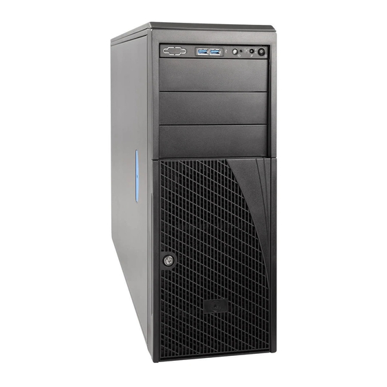
Intel P4304XXMFEN2 Manuals
Manuals and User Guides for Intel P4304XXMFEN2. We have
3
Intel P4304XXMFEN2 manuals available for free PDF download: Service Manual, Spares/Accessories List And Configuration Manual
Intel P4304XXMFEN2 Service Manual (194 pages)
Brand:
Intel
| Category:
Chassis
| Size: 23.45 MB
Table of Contents
Safety Information
5
Table of Contents
9
1 Server Building Block System Integration and Service
19
Intel® Server Chassis Identification
20
Figure 1. Intel® Server Chassis P4304XXMFEN2 - Features Overview
20
Figure 2. Intel® Server Chassis P4304XXMUXX - Optional Redundant Power Supplies
21
Server Building Block Installation
22
Chassis Side Cover Removal / Installation
22
Figure 3. Removing the Chassis Side Cover
22
Figure 4. Installing the Chassis Side Cover
23
Air Duct Removal / Installation
24
Figure 5. Installing the Air Duct 4/4
24
Figure 6. Installing the Air Duct 1/4
25
Figure 7. Installing the Air Duct 2/4
26
Figure 8. Installing the Air Duct 3/4
26
Installing the IO Shield
27
Figure 9. Installing the I/O Shield
27
Installing the Stand-Off Screws
28
Figure 10. Standoff Positions on Chassis
28
Server Board Installation
29
Figure 11. Bumper Position on Server Board
29
Figure 12. Server Board Installation
30
Power Supply Installation (P4304XXMUXX Chassis)
31
Figure 13. Installing 750W Power Supply
31
1600W Power Supply Installation (P4304XXMUXX Chassis)
32
Figure 14. PDB Location for 750W PSU
32
Figure 15. PDB Location for 1600W PSU
32
Cable Connections
33
Connecting the Power Cables to the Server Board
33
Figure 16. Installing 1600W Power Supply
33
Figure 17. Connecting Power Cables - S2600CW Server Board Family
33
Connecting the System Fan Cables to the Server Board
34
Figure 18. Connecting System Fan Cables
34
Connecting Cables from Front Panel to Server Board
35
Figure 19. Connecting Front Panel Cables - S2600CW Board Family
35
Figure 20. Connecting Front Panel - S2600ST Board Family
35
2 Essential System Component Installation
36
Processor Installation / Removal
37
For S2600CW Server Board Family
37
Figure 21. Processor Heatsink Removal
37
Figure 22. Processor Installation - Open the Socket Lever
38
Figure 23. Processor Installation - Open the Load Plate
38
Figure 24. Processor Installation - Install the Processor
39
Figure 25. Processor Installation - Remove the Socket Cover
39
Figure 26. Processor Installation - Close the Load Plate
40
Figure 27. Processor Installation - Latch the Locking Lever
40
Figure 28. Processor Heatsink Installation
41
For S2600ST Server Board Family
42
Figure 29. Processor Heat Sink Module (PHM) and Processor Socket Reference Diagram
42
Figure 30. Processor Reference Diagram - Top and Bottom Views of Processor
43
Figure 31. Processor Heat Sink
44
Figure 32. Alignment Features
45
Figure 33. Processor Carrier Clip Assembly
46
Figure 34. Processor Carrier Clip Sub-Assembly
46
Figure 35. Processor and Carrierclip Sub-Assembly to Heat Sink
47
Figure 36. Processor Heat Sink Module (PHM)
47
Figure 37. Removing the Plastic Socket Cover
48
Figure 38. PHM Alignment to Bolster Plate
49
Figure 39. Correct Placement of Processor Socket Pin
50
Figure 40. Installing the PHM
51
Figure 41. Uninstalling the PHM
52
Figure 42. Plastic Socket Cover Installation
52
Figure 43. PHM Disassembly
53
Figure 44. Releasing the Processor Carrier Clip from the Heat Sink
54
Figure 45. Releasing Processor from Carrier Clip
54
Memory Installation and Removal
55
Memory Slot Population Requirements
55
Figure 46. Intel® Server Board S2600CW DIMM Slot Layout
55
Figure 47. Intel® Server Board S2600ST Product Family Memory Slot Layout
56
Memory Installation
57
Removing Memory
57
Figure 48. Installing Memory
57
Figure 49. Removing Memory
57
Storage Device Installation/Upgrade
58
Removing the Front Bezel
62
Figure 50. Removing the Front Bezel
62
Installing the Front Bezel
63
Figure 51. Installing the Front Bezel
63
Installing a Fixed Mount Drive
64
Figure 52. Removing the EMI Cover
64
Figure 53. Releasing the Fixed Drive Trays
65
Figure 54. Securing 3.5"/2.5" Drives on a Fixed Drive Bay
65
Figure 55. Installing a Populated Fixed Drive Tray
66
Figure 56. Installing the EMI Cover
66
Figure 57. Data Cable for Fixed Storage Drives Ipc- AXXCBL450HD7S
67
Figure 58. Connecting Fixed Drive Data Cables
67
Upgrading the Fixed Drive Storage to 4X3.5" or 8X2.5" Hot-Swap Drive Bay Storage
68
Figure 59. Removing the Fixed Drive Trays
68
Figure 60. Installing the EMI Cover
69
Figure 61. Installing a 4X3.5" or 8X2.5" Hot-Swap Drive Bay Kit
69
Figure 62. Connecting Data Cables for Hot-Swap Drive Bay Kit - S2600CW Board Family
70
Figure 63. Connecting Data Cables for Hot-Swap Drive Bay Kit - S2600ST Board Family
70
Figure 64. Data Cable for Hot-Swap Drive Bay Kit Ipc- AXXCBL380HDHD
71
Figure 65. 5P to 3P I²C Cable - for S2600CW Board Family
71
Figure 66. 6P to 4P I²C Cable - for S2600ST Board Family
71
Figure 67. Backplane Connections
71
Upgrading the Fixed Drive Storage to 8X2.5" Pcie* SSD (Nvme) Combo Drive Bay Storage
72
Figure 68. Installing an Nvme Add-In Card - S2600CW Board Family
72
Figure 69. 8X2.5" Pcie* SSD (Nvme) Combo Backplane Features - Only for S2600CW Board Family
73
Figure 70. 8X2.5" Pcie* SSD (Nvme) Combo Backplane Front Side -S2600CW Board Family Only
74
Figure 71. Nvme Data Cables for 8X2.5" Pcie* SSD (Nvme) Combo Drive Bay Kit
74
Figure 72. Data Cable Connectors for Pcie* SSD Combo HSBP - S2600ST Board Family Only
76
Figure 73. 8X2.5" Pcie* SSD (Nvme) Combo Backplane Features -For S2600ST Board Family Only
77
Figure 74. Oculink Data Cable for Pcie* SSD Drives - Only for S2600ST Board Family
77
Figure 75. Backplane Cabling from Two Pcie Sources
78
Upgrading the Fixed Drive Storage to 8X3.5" Hot-Swap Drive Bay Storage
82
Figure 76. Installing Two 4X3.5" Hot-Swap Drive Bay Kits
82
Figure 77. Interconnection Diagram for Two 4X3.5" Hot-Swap Drive Bay Kits
83
Upgrading the Fixed Drive Storage to 16X2.5" Hot-Swap Drive Bay Storage
84
Figure 78. Installing Two 4X3.5" Hot-Swap Drive Bay Kits
84
Figure 79. Connecting Data Cables for Two 8X2.5" Hot-Swap Drive Bay Kits - 2600CW Board Family
85
Figure 80. Interconnect Diagram for Two 8X2.5" Hot-Swap Drive Bay Kits - S2600CW Board Family
86
Drive Carrier Extraction, Installation, and Assembly for Standard Carrieers
87
Figure 81. Installing Hot-Swap Storage Devices - Carrier Extraction
87
Figure 82. Hard Disk Drive Installation - Drive Carrier Insertion
87
Figure 83. 3.5" Hard Disk Drive Installation - Removing the Drive Blank
88
Figure 84. 3.5" Hard Disk Drive Installation - Mounting the Drive to the Carrier
88
Figure 85. Option to Install a 2.5" SSD into a 3.5" Carrier
89
Figure 86. 2.5" Storage Device Installation - Removing the Drive Blank
89
Drive Carrier Extraction, Installation, and Assembly for Tool-Less Drive Carriers
90
Figure 87. 2.5" Storage Device Installation - Mounting the Drive to the Carrier
90
Figure 88. Drive Carrier Extraction from Chassis
90
Figure 89. Drive Carrier into Chassis Installation
91
Figure 90. 2.5" Drive Carrier Assembly - Drive / Drive Blank Removal
91
Figure 91. 2.5" Drive Carrier Assembly - Drive Installation to Carrier
92
Figure 92. 2.5" Drive Carrier Assembly - Alignment Features
92
Figure 93. 3.5" Drive Carrier Assembly - Drive / Drive Blank Removal
93
Figure 94. 3.5" Drive Carrier Assembly - Drive Installation to Carrier
93
Figure 95. 3.5" Drive Carrier Assembly - Drive Blank Removal
94
Figure 96. 3.5" Drive Carrier to 2.5" SSD Bracket - Tab Removal
94
Figure 97. 3.5" Drive Carrier to 2.5" SSD Bracket - Mount SSD to Bracket
95
Figure 98. 3.5" Drive Carrier to 2.5" SSD Bracket - Mount Bracket Assembly to Carrier
95
Figure 99. 3.5" Drive Carrier to 2.5" SSD Bracket - Secure SSD to Carrier
96
Converting the Pedestal Chassis to Rack Mount Chassis
97
Removing the Front Panel Module
97
Removing the EMI Shields for 5.25" Drive Slots
97
Figure 100. Removing the Front Panel Module
97
Figure 101. Removing the EMI Shields for 5.25" Drive Slots
97
Removing the Cosmetic Top Board
98
Installing the Front Panel Module
98
Figure 102. Removing the Cosmetic Top Board
98
Figure 103. Installing the Front Panel Module
98
Installing a 5.25" Drive (Optional)
99
Installing the Rack Bezel Frame
99
Figure 104. Installing a 5.25" Drive
99
Figure 105. Installing the Rack Bezel Frame
99
Installing the Rack Mount Handles and Bezel
100
Figure 106. Installing the Rack Mount Handles
100
Figure 107. Installing the Rack Mount Bezel
100
Figure 108. Locking the Rack Mount Bezel
101
3 Option and Accessory Kit Integration and Service
102
Optical Drive - Installation and Removal
103
Optical Drive Installation
103
Figure 109. Removing the EMI Shield
103
Optical Drive Removal
104
Figure 110. Installing the Optical Drive
104
Figure 111. Removing the Optical Drive
104
ESRT2 RAID5 Key - Installation / Removal
105
Installing the ESRT2 RAID 5 Key
105
Figure 112. Re-Inserting the Empty EMI Shield
105
Figure 113. ESRT2 RAID 5 Key Location
105
Removing the ESRT2 RAID 5 Key
106
Intel® VROC Key Installation/Removal (S2600ST Server Board Family Only)
106
Installing the Intel® VROC Key
106
Removing the Intel® VROC Key
106
Figure 114. VROC Key Location
106
LSI IMR RAID5 Key - Installation / Removal (S2600CW Server Board Family Only)
107
Installing the LSI IMR RAID 5 Key
107
Removing the LSI IMR RAID 5 Key
107
Figure 115. IMR RAID 5 Key Location
107
Intel® Remote Management Module 4 Lite Key - Installation / Removal
108
Intel® RMM4 Lite Key Installation
108
Intel® RMM4 Lite Key Removal
108
Figure 116. Installing the Intel
108
Trusted Platform Module (TPM) Installation
109
For S2600CW Server Board Family
109
For S2600ST Server Board Family
109
Figure 117. Platform Module (TPM) Installation - S2600CW Board Family
109
Figure 118. Trusted Platform Module (TPM) Installation - S2600ST Board Family
109
M.2 Storage Device Installation
110
For S2600CW Server Board Family
110
Figure 119. M.2 Storage Device Installation - S2600CW Board Family
110
For S2600ST Server Board Family
111
Figure 120. M.2 Storage Device Installation - S2600ST Board Family
111
Figure 121. Installing One M.2 Storage Device - S2600ST Board Family
111
Figure 122. Installing Two M.2 Storage Devices (Dual Configuration)
112
LAN Riser Installation (S2600ST Server Board Family Only)
113
Figure 123. Dedicated Riser Slot Location
113
Figure 124. Installing the LAN Riser 1/3
114
Figure 125. Installing the LAN Riser 2/3
115
Figure 126. Installing the LAN Riser 3/3
115
BBU Bracket Installation / Removal
116
BBU Bracket Installation
116
Figure 127. Installing the BBU Bracket
116
BBU Bracket Removal
117
Figure 128. Removing the BBU Bracket
117
Connecting the Aux Power-In Cable
118
Chassis Only)
118
Figure 129. Connecting Aux Power-In Cable - Only for S2600ST Server Board Family
118
4 System Software Updates and Configuration
119
Updating the System Software Stack
119
Using the BIOS Setup Utility
119
Entering BIOS Setup
119
No Access to the BIOS Setup Utility
119
Navigating the BIOS Setup Utility
120
Table 3. BIOS Setup: Keyboard Command Bar
120
5 System Packaging Assembly Instructions
122
6 System Service - System Features Overview
126
System Feature Reference Diagrams
126
Figure 130. Intel® Server Chassis P4304XXMFEN2 Overview
126
Figure 131. Intel® Server Chassis P4304XXMUXX Overview
127
Front Drive Bay Options
127
Control Panel Features
131
Figure 132. P4304XXMFEN2/P4304XXMUXX Front Panel
131
Back Panel Features
132
Figure 133. P4304XXMFEN2 Back Panel
132
Figure 134. P4304XXMUXX Back Panel
132
Figure 135. Server Board Feature Identification
133
Server Board Features
133
Figure 136. Intel® Light-Guided Diagnostic Leds - Server Board
134
Figure 137. DIMM Fault Leds
135
Figure 138. Server Board Feature Identification
136
Figure 139. Intel® Light-Guided Diagnostic Leds - Server Board
137
Figure 140. DIMM Fault Leds
138
System Configuration and Recovery Jumpers
139
S2600CW Server Board Family
139
Figure 141. System Configuration and Recovery Jumpers
139
S2600ST Server Board Family
141
Figure 142. Configuration and Recovery Jumpers
141
7 System Service - FRU Replacement
145
System Fan Assembly Removal / Installation
145
System Fan Assembly Removal
145
Figure 143. Hot-Swap System Fan Removal
145
Figure 144. Fixed System Fan Removal
146
System Fan Assembly Installation
147
Figure 145. Hot-Swap System Fan Installation
147
Figure 146. Fixed System Fan Installation
148
Replacing the System Battery
149
Figure 147. Replacing the Backup Battery
150
Replacing the Standard Front Panel
151
Removing the Front Panel
151
Figure 148. Disconnecting the Front Panel Module
151
Figure 149. Removing the Front Panel Module
151
Installing the Front Panel Module
152
Figure 150. Removing the Front Panel Board
152
Figure 151. Installing the Front Panel Board
152
Figure 152. Installing the Front Panel
153
Figure 153. Connecting the Front Panel
153
Replacing the Server Board
154
Server Board Removal
154
Figure 154. Server Board Removal
154
Server Board Installation
155
Figure 155. Bumper Position on Server Board
155
Figure 156. Server Board Installation
156
Appendix A: Getting Help
157
Appendix B: System Cabling Routing Diagrams
158
Figure 157. P4304XXMFEN2 Cable Routing - S2600CW Server Board Family
158
Figure 158. P4304XXMUXX Cable Routing - S2600CW Server Board Family
159
Figure 159. P4304XXMFEN2 Cable Routing - S2600ST Server Board Family
160
Figure 160. P4304XXMUXX Cable Routing - S2600ST Server Board Family
160
Appendix C: System Status LED Operating States and Definition
161
Table 4. System Status LED State Definitions
161
Appendix D: POST Code Diagnostic LED Decoder Table for S2600CW Server Board Family
163
Figure 161. POST Diagnostic LED Location
163
Table 5. POST Progress Code LED Example
164
Table 6. MRC Progress Codes
165
Table 7. MRC Fatal Error Codes
166
Table 8. POST Progress Codes
167
Appendix E: POST Code Diagnostic LED Decoder Table for S2600ST Server Board Family
170
Figure 162. POST Diagnostic LED Location
170
Table 9. POST Progress Code LED Example
171
Table 10. MRC Progress Codes
171
Table 11. MRC Fatal Error Codes
174
Table 12. POST Progress Codes
175
Appendix F: POST Code Errors
184
Table 13. POST Error Codes and Messages
185
Table 14. Post Error Beep Codes
191
Table 15. Integrated BMC Beep Codes
192
Appendix G: Glossary
193
Advertisement
Intel P4304XXMFEN2 Service Manual (108 pages)
Server Chassis
Brand:
Intel
| Category:
Chassis
| Size: 12.74 MB
Table of Contents
Table of Contents
7
Server Building Block System Integration
13
Intel® Server Chassis Identification
14
Figure 1. Intel® Server Chassis P4304XXMFEN2 - Fixed Power Supply
14
Figure 2. Intel® Server Chassis P4304XXMUXX - Optional Redudant Power Supplies
14
Server Building Block Installation
15
Removing the Chassis Side Cover
15
Installing the IO Shield
15
Installing the Chassis Stand-Off
15
Server Board Installation
17
Figure 3. Server Board Installation
17
Power Supply Installation (Optional)
18
1600W Power Supply Installation (Optional)
18
Figure 4. Installing 750W Power Supply
18
Figure 5. Installing 1600W Power Supply
20
Cable Routing and Connection
21
Routing the Cables
21
Figure 6. P4304XXMFEN2 Cable Routing
21
Figure 7. P4304XXMUXX Cable Routing
22
Connecting the Power Cables to the Server Board
23
Figure 8. Connecting Power Cables
23
Connecting the System Fan Cables to the Server Board
24
Figure 9. Connecting System Fan Cables
24
Connecting the Cables to the Front Panel
25
Essential System Component Installation and Service
26
Internal Cable Routing
27
Figure 10. Internal Cable Routing
28
Chassis Side Cover Removal / Installation
29
Chassis Side Cover Removal
29
Chassis Side Cover Installation
30
Air Duct Removal / Installation
31
Air Duct Installation
31
Air Duct Removal
31
System Fan Assembly Removal / Installation
32
System Fan Assembly Removal
32
Figure 11. System Fan Assembly Removal
32
System Fan Assembly Installation
34
Figure 12. System Fan Assembly Installation
34
Processor Installation / Removal
36
Processor Heatsink(S) Removal
36
Figure 13. Processor Heatsink Removal
36
Processor Installation
37
Figure 14. Processor Installation - Open the Socket Lever
37
Figure 15. Processor Installation- Open the Load Plate
37
Figure 16. Processor Installation - Install the Processor
38
Figure 17. Processor Installation - Remove the Socket Cover
38
Figure 18. Processor Installation - Close the Load Plate
39
Figure 19. Processor Installation - Latch the Locking Lever
39
Processor Heatsink Installation
40
Removing the Processor
40
Figure 20. Processor Heatsink Installation
40
Memory Installation and Removal
41
Memory Slot Population Requirements
41
Memory Installation
41
Figure 21. Installing Memory
41
Removing Memory
42
Figure 22. Removing Memory
42
Storage Device Installation/Upgrade
43
Removing the Front Bezel
45
Installing the Front Bezel
46
Converting the Pedestal Chassis to Rack Mount Chassis
46
Installing the Fixed Drive Storage
51
Upgrading the Fixed Drive Storage to 4X3.5" or 8X2.5" Hot-Swap Drive Bay Storage
55
Upgrading the Fixed Drive Storage to 8X2.5" Pcie SSD (Nvme) Combo Drive Bay Storage
58
Upgrading the Fixed Drive Storage to 8X3.5" Hot-Swap Drive Bay Storage
62
Upgrading the Fixed Drive Storage to 16X2.5" Hot-Swap Drive Bay Storage
64
X 3.5" Front Drive Bay Storage
66
Figure 23. Installing Hot-Swap Storage Devices - 3.5" Carrier Extraction
66
Figure 24. 3.5" Hard Disk Drive Installation - Removing the Drive Blank
66
Figure 25. 3.5" Hard Disk Drive Installation - Mounting the Drive to the Carrier
67
Figure 26. Option to Install a 2.5" SSD into a 3.5" Carrier
67
Figure 27. Hard Disk Drive Installation - Inserting the 3.5" HDD Assembly
68
X 2.5" Front Drive Bay Storage
69
Figure 28. Installing Hot-Swap Storage Devices - 2.5" Carrier Extraction
69
Figure 29. 2.5" Storage Device Installation - Removing the Drive Blank
69
Figure 30. 2.5" Storage Device Installation - Mounting the Drive to the Carrier
70
Figure 31. 2.5" Storage Device Installation - Inserting the 2.5" Drive Assembly
70
Option and Accessory Kit Integration and Service
71
Optical Drive - Installation and Removal
72
Optical Drive Installation
72
Figure 32. Removing the EMI Shield
72
Figure 33. Installing the Optical Drive
72
Optical Drive Removal
73
Figure 34. Removing the Optical Drive
73
Figure 35. Re-Inserting the Empty EMI Shield
73
ESRT2 RAID5 Key - Installation / Removal
74
Installing the ESRT2 RAID 5 Key
74
Removing the ESRT2 RAID 5 Key
74
Figure 36. ESRT2 RAID 5 Key Location
74
LSI IMR RAID5 Key - Installation / Removal
75
Installing the LSI IMR RAID 5 Key
75
Removing the LSI IMR RAID 5 Key
75
Figure 37. IMR RAID 5 Key Location
75
Intel® RAID Smart Battery AXXRSBBU9 - Installation / Removal
76
Intel® RAID Smart Battery Pre-Installation Considerations
76
Installing the Intel® RAID Smart Battery
76
Figure 38. BBU Unit Connection to the RAID Card
76
Figure 39. Installing the RAID Card Again
77
Connecting the Plastic Battery Holder to the Chassis
78
Figure 40. Align the Tabs with Battery Holder
78
Removing the Intel® RAID Smart Battery
79
Figure 41. Slide the Battery Holder
79
Intel® Remote Management Module 4 Lite Key - Installation / Removal
80
Intel® RMM4 Lite Key Installation
80
Intel® RMM4 Lite Key Removal
80
Figure 42. Installing the Intel RMM4 Lite
80
Trusted Platform Module (TPM) Installation
81
Installation
81
System Software Updates and Configuration
82
Updating the System Software Stack
82
Using the BIOS Setup Utility
82
Entering BIOS Setup
82
No Access to the BIOS Setup Utility
82
Navigating the BIOS Setup Utility
83
Table 2. BIOS Setup: Keyboard Command Bar
83
System Features Overview
85
System Feature Reference Diagrams
85
Figure 43. Intel® Server Chassis P4304XXMFEN2 Features Overview
85
Front Drive Bay Options
86
Figure 44. Intel® Server Chassis P4304XXMUXX Features Overview
86
Figure 45. no Front Drive Bay Configuration - Chassis-Only Building Block
86
Control Panel Features
87
Back Panel Features
87
Figure 46. P4304XXMFEN2/P4304XXMUXX Front Panel
87
Figure 47. P4304XXMFEN2 Back Panel
87
Figure 48. P4304XXMUXX Back Panel
88
Server Board Features
89
Figure 49. Server Board Feature Identification
89
Figure 50. Intel® Light-Guided Diagnostic Leds - Server Board
90
Figure 51. DIMM Fault Leds
91
System Configuration and Recovery Jumpers
92
Figure 52. System Configuration and Recovery Jumpers
92
Figure 53. POST Diagnostic LED Location
95
Table 3. POST Progress Code LED Example
96
Table 4. MRC Progress Codes
96
Table 5. MRC Fatal Error Codes
97
Table 6. POST Progress Codes
98
Table 7. POST Error Codes and Messages
101
Table 8. POST Error Beep Codes
106
Table 9. Integrated BMC Beep Codes
107
Intel P4304XXMFEN2 Spares/Accessories List And Configuration Manual (54 pages)
Server Board/Chassis
Brand:
Intel
| Category:
Server
| Size: 2.18 MB
Table of Contents
Document Revision History
2
Table of Contents
4
1 Intel® Server Family Overview
9
Table 1. Product Family Reference Collaterals
10
Product Family Summary Chart
14
Table 2. Server Board Product Family Summary
14
Table 3. Server Chassis & Server System Product Family Summary
14
2 Server Building Block Configuration
15
Intel® Server Board S2600CW Product Family Skus
16
Ipc - DBS2600CW2R
16
Ipc - DBS2600CWTR
16
Table 4. Intel® Server Board S2600CW Product Family Skus
16
Ipc - DBS2600CW2SR
17
Ipc - DBS2600CWTSR
17
Intel® Chassis P4000 Product Family Skus
18
Ipc - P4304XXMFEN2
19
Table 5. Intel® Server Chassis P4000 Product Family Skus
19
Ipc - P4304XXMUXX
20
3 Sas/Sata Data Cable Guide
21
Sas/Sata Data Cable Connector Types
21
Table 6. Single Port SATA Connector
21
Table 7. Multiple Channel Minisas HD Connectors
21
Server System Cable Guide
22
Table 8. Multiple Channel Minisas Connectors
22
Table 9. Cable Connector Types
22
3.2.1 Fixed Hdds SAS/SATA Cable Guide
23
Table 10. Fixed HDD Configuration SATA Cable Guide
23
3.2.2 4X3.5" Hot-Swap HDD SAS/SATA Cable Guide
25
Table 11. 4X3.5" Hot-Swap HDD Configuration Cable Guide
25
3.2.3 8X3.5" Hot-Swap HDD SAS/SATA Cable Guide
26
Table 12. 8X3.5" Hot-Swap HDD Configuration Cable Guide
26
3.2.4 8X2.5" Hot-Swap HDD SAS/SATA Cable Guide
27
Table 13. 8X2.5" Hot-Swap HDD Configuration Cable Guide
27
3.2.5 16X2.5" Hot-Swap SAS/SATA HDD Cable Guide
28
Table 14. 16X2.5" Hot-Swap HDD Cable Guide (with no SAS Expander)
28
Ipc - RES3FV288
29
Ipc - RES3TV360
29
Table 15. SAS Expanders Compatible with Intel® Server Boards S2600CW Family
29
Table 16. Hot-Swap HDD Cable Guide (with SAS Expander)
30
8X2.5" Hot-Swap HDD SAS/SATA Cable Guide for Combo Pcie* SFF (Nvme) SSD / SAS Backplane (Ipc FUP8X25S3HSDK)
31
Table 17. Combo Backplane Module Placement - 8 X 2.5" Front Drive Configurations
31
3.2.7 16X2.5" Hot-Swap SAS/SATA HDD with Combo Pcie* SFF (Nvme) SSD / SAS Backplane (Ipc FUP8X25S3HSDK) Cable Guide
32
Table 18. Combo Backplane Module Placement - 16 X 2.5" Front Drive Configurations
32
Intel® SAS / SATA Data Cable Kits
33
Table 19. Storage Data Cable Kit Description and Order Information
33
Product Description
34
4 Intel Server System Configuration Options
35
Intel® SAS/SATA Backplane Options
35
Ipc - FUP4X35S3HSBP
35
Ipc - FXX8X25S3HSBP
35
Ipc - FUP4X35S3HSDK
35
Ipc - FUP8X25S3HSDK
35
Table 20. Intel® SAS Bridge Board
35
Ipc - FUP8X25S3NVDK
36
Ipc - FXX35HSADPB
36
Ipc - FXX25HSCAR
36
Locking Front Bezel Accessory Kit
37
Ipc - FUPBEZELHSD2
37
Table 21. List of Front Bezel Accessory Kit
37
Intel® SAS RAID Add-In Cards, Expanders and Accessories
38
Intel® RAID Controller Add-In Cards - SAS 3.0 (12Gb/S)
38
Ipc - RS3GC008
38
Ipc - RS3SC008
38
Table 22. List of Intel® RAID Controller Add-In Cards - SAS 3.0 (12Gb/S)
38
4.3.2 Intel® SAS Expanders
39
Ipc - RES3FV288
39
Ipc - RES3TV360
39
Table 23. SAS Expanders Compatible with Intel® Server Boards S2600CW Family
39
4.3.3 Intel® RAID Accessoried Options
40
Ipc - RKSATA4R5
40
Ipc - AXXRPFKHY5
40
Ipc - RMS25KB080
40
Ipc - RMS25KB040
40
Table 24. List of Intel® RAID Accessoried Options
40
Ipc - RMS25PB080
41
Ipc - RMS25PB040
41
Ipc - RMT3PB080
41
Ipc - AXXRMFBU2
41
Ipc - AXXRSBBU9
41
Intel® Power Supply Module and Power Cords
42
Ipc - FXX750PCRPS
42
Ipc - FXX1600PCRPS
42
Ipc - FUPNRPSADP
42
Ipc - FUPCRPSCAGE
42
Table 25. Intel® Power Supply Module and Power Cords
42
Ipc - FUPPDBHC2
43
Ipc - FPWRCABLENA
43
Rack Options
44
4.5.1 Rack Bezel Accessories
44
Ipc - AUPBEZEL4UF
44
Ipc - AUPBEZEL4UD
44
Table 26. List of Rack Bezel Accessories
44
4.5.2 Rack Mount Kits
45
Ipc - AXXELVRAIL
45
Ipc -AXX3U5UPRAIL
45
Ipc -AXX3U5UCMA
45
Table 27. List of Rack Mount Kits
45
5 Miscellaneous Accessory Options
46
Ipc - AXXRMM4LITE
46
Ipc - AXXTPME5
46
Table 28. List of Miscellaneous Accessory Options
46
Ipc - AXXTPME6
47
Ipc - AXXTPME7
47
Ipc - BXSTS200C
48
Ipc - BXSTS200P
48
Ipc - AUPCWPBTP
48
Ipc - AUPMCOPROBR
48
6 Spare and Replacement Parts (Frus)
49
Ipc -FUP550SNRPS
49
Ipc - FXXFPANEL
49
Ipc - FUPBEZELFIX2
49
Ipc - A4UCWDUCT
49
Ipc - AXXCWIOS
49
Table 29. List of Spare and Replacement Parts
49
Ipc - FUP4X35NHDK
50
Ipc - FUPMMSK
50
Ipc - FUPMESK
50
Ipc - FUPMLHSFAN
50
Ipc - FUPNHFANCPU
51
Ipc - FUPMNHFANPCI
51
7 Software Security - Mcafee® Antivirus for Intel® Server Systems
52
How to Order It
52
Mcafee® Antivirus for Intel® Server Systems Skus
52
Table 30. Mcafee® Antivirus for Intel® Server Systems Skus
52
8 Extended Warranty
53
Table 31. Extended Warranty
53
Table 32. a List of Acronyms and Terms Used Throughout this Document
54
Advertisement
Advertisement
Related Products
Intel P4304XXMUXX
Intel P4000S Series
Intel P4304 SFCN Series
Intel P4304XXSHCN
Intel P4304XXSFCN
Intel P4304SC2SFEN
Intel P4304SC2SHDR
Intel P4304BT series
Intel P4304CR2LFJNL
Intel P4304CR2LFKN
Intel Categories
Motherboard
Computer Hardware
Server
Server Board
Desktop
More Intel Manuals
Login
Sign In
OR
Sign in with Facebook
Sign in with Google
Upload manual
Upload from disk
Upload from URL