Table of Contents
Advertisement
Quick Links
Download this manual
See also:
Instruction Manual
Advertisement
Table of Contents

Related Manuals for Danfoss AAF00x


Summary of Contents for Danfoss AAF00x
- Page 1 MAKING MODERN LIVING POSSIBLE VLT® Active Filter AAF00x Operating Instructions...
-
Page 2: Table Of Contents
2.1.2 General Warning 2.1.3 Before Commencing Repair Work 2.1.4 Special Conditions 2.1.5 Avoid Unintended Start 2.1.6 IT Mains 3 Introduction to VLT Active Filter AAF00x 3.1.1 Working Principle 3.1.2 Filter Configurator 3.1.3 Ordering Form type code 4 How to Install 4.1 How to Get Started... - Page 3 7.3.6 The Data Field 7.3.8 Parameter Number (PNU) 7.3.9 Index (IND) 7.3.10 Parameter Value (PWE) 7.3.11 Data Types Supported by VLT AutomationDrive 7.3.12 Conversion 7.3.13 Process Words (PCD) 7.4 How to Access Parameters MG.90.V2.02 - VLT® is a registered Danfoss trademark...
- Page 4 Contents VLT Active Filter AAF 00x 7.4.1 Parameter Handling 7.4.3 IND 7.4.4 Text Blocks 7.4.5 Conversion Factor 7.4.6 Parameter Values 8 General Specifications 8.1 Electrical Data 8.1.1 Power Rating 9 Troubleshooting MG.90.V2.02 - VLT® is a registered Danfoss trademark...
-
Page 5: How To Read These Operating Instructions
In no event shall Danfoss be liable for direct, indirect, special, incidental, or consequential damages arising out of the use, or the inability to use information contained in this manual, even if advised of the possibility of such damages. -
Page 6: Safety
Installation at high altitudes Wait at least the amount of time indicated in NOTE section General Warning above At altitudes above 3km, please contact Danfoss Drives regarding PELV Failure to follow recommendations could result in death or serious injury. 2.1.4 Special Conditions... -
Page 7: Avoid Unintended Start
For 400V IT mains and delta earth (grounded leg), mains voltage may exceed 440V between phase and earth. 14-50 RFI Filter can be used to disconnect the internal RFI capacitors from the RFI filter to ground. MG.90.V2.02 - VLT® is a registered Danfoss trademark... -
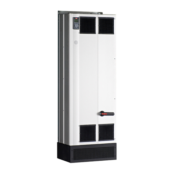
Page 8: Introduction To Vlt Active Filter Aaf00X
IGBT switches in real time feeding a DC-voltage into the grid. The compensated current waveform is ® Active Filter AAF00x is a device for harmonic current smoothened via a built-in LCL filter making sure that the mitigation and reactive current compensation. The unit is... -
Page 9: Filter Configurator
Furthermore, you can establish a project list with several products and send it to a Danfoss sales representative. The configurator can be found on the global Internet site: www.danfoss.com/drives. Filters will automatically be delivered with a language package relevant to the region from which it is ordered. -
Page 10: Ordering Form Type Code
AX: No A option B options 31-32 BX: No B option C-option configu- 33-37 CFxxx: CO-option occupied with ration Active Filter control card D options 38-39 DO: 24V backup DX: No Options MG.90.V2.02 - VLT® is a registered Danfoss trademark... -
Page 11: How To Install
Keep the filter on the pallet and boxed, as long as possible to avoid scratches and dents. Illustration 4.1 Diagram showing basic installation including mains and CTs. MG.90.V2.02 - VLT® is a registered Danfoss trademark... -
Page 12: Lifting
The lifting bar must be able to handle the weight of the unit. See Mechanical Dimensions for the weight of the different frame sizes. Maximum diameter for bar is 25mm (1 inch). The angle from the top of the unit to the lifting cable should be 60° or greater. MG.90.V2.02 - VLT® is a registered Danfoss trademark... -
Page 13: Mechanical Dimensions
The plinth of the D and E-frames filters should be mounted before the unit is lifted to its final position. 4.2.5 Mechanical Dimensions 1853,6 1733,6 [73] [68] 1553,4 [61] 200.0 377,8 [15] Illustration 4.4 Frame size D9, AAF05 MG.90.V2.02 - VLT® is a registered Danfoss trademark... - Page 14 VLT Active Filter AAF 00x 1732 [68.2] 1781 [70.1] 1553 [61.1] [7.9] [23.7] [14.9] Illustration 4.5 Frame size D13, AAF06 2119,8 2000,1 [83] [79] 1549,9 [61] 159,2 493,5 [19] Illustration 4.6 Frame size E7, AAF05 MG.90.V2.02 - VLT® is a registered Danfoss trademark...
- Page 15 How to Install VLT Active Filter AAF 00x 2000 [78,78] 1498 2004.50 mm [59,06] 1491.35 mm [7,68] 491,19 493.23 mm [19,43] Illustration 4.7 Frame size E9, AAF06 MG.90.V2.02 - VLT® is a registered Danfoss trademark...
- Page 16 Type 1 Nominal current rate 190A 250A Shipping Dimensions Height 1852 2111 (mm) Width 1118 1118 (mm) Depth (mm) Weight (kg) Filter Dimensions Height 1732 2000 (mm) Width (mm) Depth (mm) Weight (kg) MG.90.V2.02 - VLT® is a registered Danfoss trademark...
- Page 17 Type 1/12 Nominal current rate 190A 250, 310, 400A Shipping Dimensions Height (mm) Width (mm) Depth 1943 2203 (mm) Weight (kg) Filter Dimensions Height 1740 2000 (mm) Width (mm) Depth (mm) Weight (kg) MG.90.V2.02 - VLT® is a registered Danfoss trademark...
-
Page 18: Mechanical Installation
[33] 849.1 [33.4] 889,1 3x771.0 [35] [30.4] Illustration 4.8 Space in front of IP21/IP54 enclosure type, frame size D9 . Illustration 4.10 Space in front of IP21/IP54 enclosure type, frame size E7. MG.90.V2.02 - VLT® is a registered Danfoss trademark... -
Page 19: Terminal Locations - Frame Size D
4.3.3 Terminal Locations - Frame size D eration when designing the cable access. Consider the following position of the terminals when designing for cables access. 332.5 [13.1] [.0] Illustration 4.14 Terminal Location of Frame E7 MG.90.V2.02 - VLT® is a registered Danfoss trademark... -
Page 20: Cooling And Airflow
27.3 45.9 89.3 115.7 (Pa) Pressure Increase Illustration 4.16 D frame Derating vs. Pressure Change Air flow: 450 cfm (765 m MG.90.V2.02 - VLT® is a registered Danfoss trademark... - Page 21 74.6 84.6 [10] [.2] [3.5] 2X 112.75 202.75 [4.5] 20,0 2X 222.75 361.7 [14.5] 380,0 [15] Illustration 4.18 Frame Size D9 2X 200 2X 370 [2.5] [15] Illustration 4.21 Frame Size E9 MG.90.V2.02 - VLT® is a registered Danfoss trademark...
-
Page 22: Field Installation Of Options
Disconnect and Fuses & RFI Fuses, RFI & None Fuse Disconnect 177G2348 177G2344 177G2346 177G2347 177G2343 177G2345 176F0253 176F0255 176F0257 176F0258 176F0260 177G2348 177G2344 177G2346 177G2347 177G2343 177G2345 176F0253 176F0255 176F0257 176F0258 176F0260 MG.90.V2.02 - VLT® is a registered Danfoss trademark... -
Page 23: Electrical Installation
(4/0) 150mm (300MCM) 4x240mm (4x500MCM) 310A 240 mm (500MCM) 2*95mm (2*3/0) 4x240mm (4x500MCM) 400A 2*95mm (2*3/0) 2*150mm (2*300MCM) 4x240mm (8x900MCM) Table 4.2 Allowed Active Filter Mains Cable with Typical Cable Manufacturer Data MG.90.V2.02 - VLT® is a registered Danfoss trademark... - Page 24 Recommended fuses can be seen in the tables of the fuse section. Always ensure that proper fusing is made according to local regulation. Illustration 4.23 Frame size D9 LCL line reactor Mains wire connection LCL capacitors LCL filter reactor CT-wire connection point Input plate Fan/ SMPS fuse Backchannel fan MG.90.V2.02 - VLT® is a registered Danfoss trademark...
- Page 25 Illustration 4.24 Frame size D13 CT - connection terminal Mains contactor FC card Power card AFC card Mains wire connection RFI (input option plate) Back channel Fuse/disconnect (mains option) LCL circuitry LCL circuitry DC-capacitors MG.90.V2.02 - VLT® is a registered Danfoss trademark...
- Page 26 How to Install VLT Active Filter AAF 00x Illustration 4.25 Frame size E7 LCL line reactor Mains wire connection LCL capacitors LCL filter reactor CT-wire connection point Input plate Fan/ SMPS fuse Backchannel fan MG.90.V2.02 - VLT® is a registered Danfoss trademark...
- Page 27 CT - connection terminal Mains contactor FC card Power card AFC card Mains wire connection RFI (input option plate) Back channel Fuse/disconnect (mains option) LCL circuitry LCL circuitry DC-capacitors Table 4.3 Frames Sizes D13 MG.90.V2.02 - VLT® is a registered Danfoss trademark...
- Page 28 ELCB, RCD, GFCI relays or multiple protective earthings are often used as extra protection, or needed to provide compliance with local safety regulations. In case of an earth fault, a DC component may develop in the fault MG.90.V2.02 - VLT® is a registered Danfoss trademark...
-
Page 29: Current Transformer (Ct)
[VA] = 25*[Ohm/M] *[M]+1.25 The current transformers are not part of the filter package [Ohm/M] being the cable resistance in Ohm/meter, [M] and must be purchased separately. being the cable length in meters MG.90.V2.02 - VLT® is a registered Danfoss trademark... - Page 30 Individual or group compensation The compensation of the filter depends on the signal that is returned from the current transformers. The point of installation for these sensors is so determine the loads that are corrected. MG.90.V2.02 - VLT® is a registered Danfoss trademark...
- Page 31 PCC2 Illustration 4.31 Current transformers are installed in front of distribution bus 2 and one frequency converter and the filter only compensating currents for those. CT on load side. MG.90.V2.02 - VLT® is a registered Danfoss trademark...
-
Page 32: Auto Ct Detection
The Auto CT detection is pending on the follow conditions: Active Filter bigger than 10% of CT RMS rate CTs installed on source (PCC) side (auto CT not possible for load side CT installation) MG.90.V2.02 - VLT® is a registered Danfoss trademark... -
Page 33: Active Filter Operating With Capacitor Banks
Illustration 4.35 Summation CTs example for individual harmonic compensation (load side). Summation current transformers are available with multiple (2-5) inputs and common output. For application where summations CTs are used to add current from MG.90.V2.02 - VLT® is a registered Danfoss trademark... - Page 34 Summation CT can also be used to subtract two signals from each other and so subtract the capacitor bank corrected current from the total current PCC1 Illustration 4.37 Not allowed installation. Corrected capacitor current interacts with CT measurement. MG.90.V2.02 - VLT® is a registered Danfoss trademark...
-
Page 35: Fuses
The Active Filter must be protected against short-circuit to path inside the filter and tied down with other control avoid electrical or fire hazard. Danfoss recommends using wires (see Illustration 4.40 ). the fuses mentioned below to protect service personnel and equipment in case of an internal failure in the device. - Page 36 To remove the cable from the terminal: Insert a screw driver in the square hole. Pull out the cable. Illustration 4.40 Example of Control Card Wiring Path, D13. 1) Max. 0.4 x 2.5mm MG.90.V2.02 - VLT® is a registered Danfoss trademark...
-
Page 37: Unscreened Control Wires
Internal supply S, T The connector located on the power card provides the connection of line voltage for the cooling fans. The fans are connected from factory to be supplied form a common MG.90.V2.02 - VLT® is a registered Danfoss trademark... -
Page 38: Electrical Installation, Control Cables
Active Filter. MK108 1A CT-connection pin MK102 I/O connections MK101 5A CT-connection pin 91-93 Mains input MK103 Software communication RS-485 MG.90.V2.02 - VLT® is a registered Danfoss trademark... - Page 39 To comply with EMC emission specifications, screened cables are recommended. If an unscreened cable is used, see 4.5.15 Unscreened Control Wires. If unscreened control cables are used, it is recommended to use ferrite cores to improve EMC performance. MG.90.V2.02 - VLT® is a registered Danfoss trademark...
-
Page 40: Paralleling Of Active Filter Units
CT VA-rating. [M] = ([VA]-1,25) / (25*[Ohm/M]) See 4.5.1 Power Connections for more details. MG.90.V2.02 - VLT® is a registered Danfoss trademark... - Page 41 CT no other follower have the same follower ID. configuration. The automatic CT-detection is still effective for filters in master-follower configuration but it is recommend setting MG.90.V2.02 - VLT® is a registered Danfoss trademark...
-
Page 42: Final Set-Up And Test
300-29 Start Auto CT Detection. start operation. Filter supports all standard CTs with 1A or 5A secondary CT detection failed: rating. Danfoss CT auto detection support most standard CTs. The auto CT detection will not succeed if: • CTs are not wired correctly •... - Page 43 That means that 300-25 CT Polarity filter is ready to start it operation. To setup the filter need to be set for all three CTs individually. compensation mode and priority please consult the chapter How to programme. MG.90.V2.02 - VLT® is a registered Danfoss trademark...
- Page 44 - Record THDv and THDi improvements Performance available - RMS - True PF and displacement PF Check that THDi read out Check CT value is reduced to 5-9% settings again when lter is turned on MG.90.V2.02 - VLT® is a registered Danfoss trademark...
-
Page 45: How To Operate The Active Filter
0-20 Display Line 1.1 Small to 0-24 Display Line 3 Large, which can be accessed via [QUICK MENU], "Q3 Function Setups", "Q3-1 General Settings", "Q3-11 Display Settings". MG.90.V2.02 - VLT® is a registered Danfoss trademark... - Page 46 Press [status] and [▼] for brighter display The Main Menu parameters can be accessed immediately unless a password has been created via 0-60 Main Menu Password, 0-61 Access to Main Menu w/o Password, MG.90.V2.02 - VLT® is a registered Danfoss trademark...
- Page 47 [Hand on] – [Auto on]. [Reset] is used for resetting the filter after an alarm (trip). The key can be Enabled [1] or Disabled [0] via 0-43 [Reset] Key on LCP. MG.90.V2.02 - VLT® is a registered Danfoss trademark...
-
Page 48: Tips And Tricks
LCP or on a PC via MCT 10 key reduces the data value. Place the cursor on the value Set-up Software. to be saved and press [OK]. MG.90.V2.02 - VLT® is a registered Danfoss trademark... - Page 49 15-30 Alarm Log: Error Code to 15-32 Alarm Log: Time at both ends. If the unit is the first or the last device in the RS-485 loop, set the switch S801 on the control card for ON.. MG.90.V2.02 - VLT® is a registered Danfoss trademark...
- Page 50 MCT 10 Set-up Software has been designed as an easy to is connected via a standard (host/device) USB cable to use interactive tool for setting parameters in our Active both devices, or via the RS-485 interface Filters. The software can be downloaded from the Danfoss internet site http://www.Danfoss.com/BusinessAreas/Drives- NOTE Solutions/Softwaredownload/DDPC+Software +Program.htm.
- Page 51 Ordering number: Please order the CD containing MCT 10 Set-up Software using code number 130B1000. MCT 10 Set-up Software can also be downloaded from the Danfoss Internet: WWW.DANFOSS.COM, Business Area: Motion Controls. MG.90.V2.02 - VLT® is a registered Danfoss trademark...
-
Page 52: How To Programme
0-24 Display Line 3 Large Mains frequency 15-51 Frequency Converter Serial Number Efficient parameter set-up for most applications The parameters can easily be set up for most the applications only by using the [Quick Menu]. MG.90.V2.02 - VLT® is a registered Danfoss trademark... - Page 53 0-20 Display Line 1.1 Small Power Factor 0-21 Display Line 1.2 Small THD of current 0-22 Display Line 1.3 Small Mains Current 0-23 Display Line 2 Large Output Current 0-24 Display Line 3 Large Mains Frequency MG.90.V2.02 - VLT® is a registered Danfoss trademark...
- Page 54 After selecting a parameter group, choose a parameter with the navigation keys. The middle section on the GLCP display shows the parameter number and name as well as the selected parameter value. MG.90.V2.02 - VLT® is a registered Danfoss trademark...
-
Page 55: Main Menu
Part of Language package 2 enable quicker commissioning if similar parameter settings Turkish Part of Language package 4 are required in different setups. Trad.Chinese Part of Language package 2 Bulgarian Part of Language package 3 MG.90.V2.02 - VLT® is a registered Danfoss trademark... - Page 56 The link will functions. ensure synchronising of the ‘not changeable Factory setup Cannot be changed. It contains the Danfoss during operation’ parameter values when data set, and can be used as a data source moving from one set-up to another during when returning the other set-ups to a operation.
- Page 57 Alarm Word 2 One or more alarms in a Hex code. [1692] Warning Word One or more warnings in a Hex code. [1693] Warning Word 2 One or more warnings in a Hex code. MG.90.V2.02 - VLT® is a registered Danfoss trademark...
- Page 58 Password Avoids unauthorised start in Auto mode. If listed in 0-20 Display Line 1.1 Small. 0-42 [Auto on] Key on LCP is included in the Quick Menu, then define the password in 0-65 Quick Menu Password. MG.90.V2.02 - VLT® is a registered Danfoss trademark...
- Page 59 Menu w/o Password will be ignored. running. 0-51 Set-up Copy Option: Function: No copy No function Copy to set- Copies all parameters in the present up 1 Programming Set-up (defined in 0-11 Programming Set-up) to Set-up 1. MG.90.V2.02 - VLT® is a registered Danfoss trademark...
-
Page 60: Digital I/O Mode
PNP or NPN Option: Function: systems. No operation No reaction to signals transmitted to the PNP Action on positive directional pulses (↕). PNP systems terminal. are pulled down to GND. MG.90.V2.02 - VLT® is a registered Danfoss trademark... - Page 61 5-12 Terminal 27 Digital Input Option: Function: No Operation Functions are described under 5-1* Digital Inputs 5-13 Terminal 29 Digital Input Option: Function: No Operation Functions are described under 5-1* Digital Inputs MG.90.V2.02 - VLT® is a registered Danfoss trademark...
- Page 62 The unit is ready for operation and applies a supply signal on the control board. Enable / no Ready for operation. No start or stop warning command is been given (start/disable). No warnings are active. MG.90.V2.02 - VLT® is a registered Danfoss trademark...
- Page 63 P 5-41 P 5-42 Option: Function: If the selected Event condition changes before the on- or No operation off delay timer expires, the relay output is unaffected. [128] SC contactor [129] Mains contactor MG.90.V2.02 - VLT® is a registered Danfoss trademark...
-
Page 64: General Settings
8-06 Reset Control Timeout toggles. Then out. The time-out counter is triggered by the unit resumes its original set-up. a valid control word. Resume set- Resumes the set-up active prior to the time- out. MG.90.V2.02 - VLT® is a registered Danfoss trademark... - Page 65 Logic AND Activates the set-up selection via the fieldbus/ serial communication port, AND additionally Range: Function: via one of the digital inputs. Application [Application Specify the maximum dependent dependant] permissible delay time MG.90.V2.02 - VLT® is a registered Danfoss trademark...
- Page 66 Activate the set-up selection via the fieldbus/ serial communication port OR via one of the digital inputs. NOTE This parameter is active only when 8-01 Control Site is set to [0] Digital and control word. MG.90.V2.02 - VLT® is a registered Danfoss trademark...
-
Page 67: Trip Reset
14-20 Reset Mode is set to Automatic reset [1] - [13]. 14-22 Operation Mode Option: Function: Use this parameter to specify normal operation; to perform tests; or to initialise all parameters except 15-03 Power Up's, MG.90.V2.02 - VLT® is a registered Danfoss trademark... -
Page 68: Operating Data
15-10 Logging Source 6.7 15-0* Operating Data Array [4] Option: Function: Parameter group containing filter information such as Select which variables are to be operating data, hardware configuration and software logged. versions. None MG.90.V2.02 - VLT® is a registered Danfoss trademark... - Page 69 [0 - 100 ] Enter the percentage of all samples prior to a trigger event which are to be retained in the log. See also 15-12 Trigger Event and 15-13 Logging Mode. MG.90.V2.02 - VLT® is a registered Danfoss trademark...
- Page 70 10 fault logs can be viewed. [0] is the most recent logged version’) consisting of power SW and control SW. data, and [9] the oldest. Error codes, values, and time stamp can be viewed for all logged data. MG.90.V2.02 - VLT® is a registered Danfoss trademark...
- Page 71 [0 - 0 ] Shows the typecode string for the options (CXXXX if no option) and the translation i.e. >No option<. 15-61 Option SW Version Range: Function: [0 - 0 ] View the installed option software version. MG.90.V2.02 - VLT® is a registered Danfoss trademark...
-
Page 72: General Status
16-34 Heatsink Temp. Range: Function: [0 - 255 C] View the heatsink temperature. The cut-out limit is 90 ± 5 °C, and the filter cuts back in at 60 ± 5 °C. MG.90.V2.02 - VLT® is a registered Danfoss trademark... - Page 73 [0 - 4294967295 ] View the warning word sent via the serial communication port in hex code. 16-93 Warning Word 2 Range: Function: [0 - 4294967295 ] View the warning word sent via the serial communication port in hex code. MG.90.V2.02 - VLT® is a registered Danfoss trademark...
- Page 74 AF is a master or a follower active filter. 300-25 CT Polarity Follower Option: Function: Not Paralleled Normal Inverse Enter the polarity of the current transformers. Alternatively, this value can be determined by MG.90.V2.02 - VLT® is a registered Danfoss trademark...
- Page 75 5 sec. to avoid contact bounce. [0] Disabled Default filter does not use the sleep mode function. [1] Enabled The filter enters sleep mode at light loads or if triggered from external. MG.90.V2.02 - VLT® is a registered Danfoss trademark...
- Page 76 This value is estimated because the active filter does not measure the mains voltage. 301-12 Power Factor Range: Function: 0.00 [0.00 - 2.00 ] View the power factor, after compensation by the active filter. MG.90.V2.02 - VLT® is a registered Danfoss trademark...
-
Page 77: Parameter Lists
Integer 16 Int16 Integer 32 Int32 Unsigned 8 Uint8 Unsigned 16 Uint16 Unsigned 32 Uint32 Visible String VisStr Normalized value 2 bytes Bit sequence of 16 boolean variables Time difference w/o date TimD MG.90.V2.02 - VLT® is a registered Danfoss trademark... -
Page 78: Operation/Display 0
Access to Main Menu w/o Password [0] Full access 1 set-up TRUE Uint8 0-65 Quick Menu Password 200 N/A 1 set-up TRUE Int16 0-66 Access to Quick Menu w/o Password [0] Full access 1 set-up TRUE Uint8 MG.90.V2.02 - VLT® is a registered Danfoss trademark... -
Page 79: Digital In/Out 5
8-37 Max Inter-Char Delay 25 ms 1 set-up TRUE Uint16 8-5* Digital/Bus 8-53 Start Select [3] Logic OR All set-ups TRUE Uint8 8-55 Set-up Select [3] Logic OR All set-ups TRUE Uint8 MG.90.V2.02 - VLT® is a registered Danfoss trademark... -
Page 80: Special Functions 14
All set-ups TRUE Int32 14-5* Environment 14-50 RFI Filter [1] On 1 set-up FALSE Uint8 14-53 Fan Monitor [1] Warning All set-ups TRUE Uint8 14-54 Bus Partner 1 N/A 2 set-ups TRUE Uint16 MG.90.V2.02 - VLT® is a registered Danfoss trademark... -
Page 81: Fc Information
15-75 Slot C0 Option SW Version 0 N/A All set-ups FALSE VisStr[20] 15-76 Option in Slot C1 0 N/A All set-ups FALSE VisStr[30] 15-77 Slot C1 Option SW Version 0 N/A All set-ups FALSE VisStr[20] MG.90.V2.02 - VLT® is a registered Danfoss trademark... -
Page 82: Data Readouts
All set-ups FALSE Uint32 16-92 Warning Word 0 N/A All set-ups FALSE Uint32 16-93 Warning Word 2 0 N/A All set-ups FALSE Uint32 16-94 Ext. Status Word 0 N/A All set-ups FALSE Uint32 MG.90.V2.02 - VLT® is a registered Danfoss trademark... -
Page 83: Af Settings 300
All set-ups TRUE Uint32 301-2* Mains Status 301-20 Mains Current [A] All set-ups TRUE Int32 301-21 Mains Frequency 0 Hz All set-ups TRUE Uint8 301-22 Fund. Mains Current [A] All set-ups TRUE Int32 MG.90.V2.02 - VLT® is a registered Danfoss trademark... -
Page 84: Installation And Setup
7.1.3 RS-485 Bus Termination Screened, twisted-pair cables are recommended in order to reduce noise between conductors. Use the terminator dip switch on the main control board of the unit to terminate the RS-485 bus. MG.90.V2.02 - VLT® is a registered Danfoss trademark... -
Page 85: Network Configuration
VLT Active Filter AAF 00x NOTE The FC protocol, also referred to as FC bus or Standard bus, is the Danfoss standard fieldbus. It defines an access The factory setting for the dip switch is OFF. technique according to the master-slave principle for communications via a serial bus. -
Page 86: Telegram Length (Lge)
7.3.6 The Data Field The structure of data blocks depends on the type of telegram. There are three telegram types, and the type applies for both control telegrams (master=>slave) and response telegrams (slave=>master). MG.90.V2.02 - VLT® is a registered Danfoss trademark... - Page 87 Parameter value transferred (word) Parameter value transferred (double Bits no. 12-15 transfer parameter commands from master word) to slave and return processed slave responses to the master. Command cannot be performed text transferred MG.90.V2.02 - VLT® is a registered Danfoss trademark...
-
Page 88: Parameter Number (Pnu)
[4] corresponds to Danish, select the data value by 4-12 Motor Speed Low Limit [Hz] has a conversion factor of entering the value in the PWE block. See Example - 0.1. Selecting a data value. Serial communication is only MG.90.V2.02 - VLT® is a registered Danfoss trademark... -
Page 89: Process Words (Pcd)
(20 characters). The PNU (Parameter Number) is translated from the register address contained in the Modbus read or write message. The parameter number is translated to Modbus as (10 x parameter number) DECIMAL. MG.90.V2.02 - VLT® is a registered Danfoss trademark... -
Page 90: General Specifications
Minimum cross section to control terminals 0.25mm CT terminals specification: Needed CT number 3 (one for each phase) AAF's burden equals 2mΩ Secondary current rating 1A or 5A (hardware setup) Accuracy Class 0.5 or better MG.90.V2.02 - VLT® is a registered Danfoss trademark... - Page 91 EN 61800-3, EN 61000-6-3/4, EN 55011, IEC 61800-3 EN 61800-3, EN 61000-6-1/2, EMC standards, Immunity EN 61000-4-2, EN 61000-4-3, EN 61000-4-4, EN 61000-4-5, EN 61000-4-6 Control card performance: Scan interval : 5ms MG.90.V2.02 - VLT® is a registered Danfoss trademark...
- Page 92 21H2GCxx Total Current Losses Watt [kW] Needed Airflow 1230 1230 1230 Frame Nominal Reactive Nominal Harmonic Max individual harmonic compensation in back channel Nominal/ (maximum) Note: Numbers are rounded to nearest amp MG.90.V2.02 - VLT® is a registered Danfoss trademark...
- Page 93 1000 1500 2000 2500 3000 Altitude (meters above sea level)* Altitude (meters above sea level)* Derating of output current versus altitude at T for frame sizes D, E and F. AMB, MAX MG.90.V2.02 - VLT® is a registered Danfoss trademark...
-
Page 94: Troubleshooting
14-53 Heatsink temp Inrush fault fieldbus fault Option fault Internal fault Heatsink sensor Overload of Digital Output Terminal 27 5-00, 5-01 Overload of Digital Output Terminal 29 5-00, 5-02 Pwr. card supply MG.90.V2.02 - VLT® is a registered Danfoss trademark... - Page 95 A trip lock is an action when an alarm occurs, which may cause damage to the device or connected parts. A Trip Lock situation can only be reset by a power cycling. MG.90.V2.02 - VLT® is a registered Danfoss trademark...
- Page 96 See also 16-90 Alarm Word, 16-92 Warning Word and 16-94 Ext. Status Word. “Reserved” means that the bit is not guaranteed to be any particular value. Reserved bits should not be used for any purpose. MG.90.V2.02 - VLT® is a registered Danfoss trademark...
- Page 97 Change the ramp type 15-50 SW ID Power Card Activate the functions in 2-10 Brake Function 15-60 Option Mounted Increase 14-26 Trip Delay at Inverter Fault 15-61 Option SW Version (for each option slot) MG.90.V2.02 - VLT® is a registered Danfoss trademark...
- Page 98 Check for loose or missing wiring For the D, E, and F Frame filters, the regulated voltage to the fans is monitored. It may be necessary to contact your Danfoss supplier or service department. Note the code number for further Troubleshooting: troubleshooting directions.
- Page 99 The scaling card is the incorrect part number or not If a 24V DC power supply is used, verify proper installed. Also MK102 connector on the power card could supply power. not be installed. MG.90.V2.02 - VLT® is a registered Danfoss trademark...
- Page 100 ALARM 248, Illegal power section configuration This alarm is only for F Frame frequency converters. It is equivalent to Alarm 79. The report value in the alarm log indicates which power module generated the alarm: MG.90.V2.02 - VLT® is a registered Danfoss trademark...
- Page 101 Check that the CT parameter placement Verify if: (parameter 300-26) corresponds to the installation • • Ambient temperature is too high Perform the Mains Resonance Test () • Incorrect clearance above and below the unit MG.90.V2.02 - VLT® is a registered Danfoss trademark...
- Page 102 CTs. Program the CT parameters manually if auto CT detection fails. WARNING 318, CT ratio error The auto CT function could not determine the correct primary rating of the CTs. MG.90.V2.02 - VLT® is a registered Danfoss trademark...
- Page 103 130R0506 MG90V202 Rev. 2011-04-08 *MG90V202*...
Need help?
Do you have a question about the AAF00x and is the answer not in the manual?
Questions and answers