Advertisement
Installation Guide
SISO LCL and LC Filters
VACON® Power Options
1 Overview
SISO Filters
1.1
SISO (Sine In – Sine Out) LCL and LC filters combine both differential (DM) and common-mode (CM) filtering. SISO filters enable
installations without a transformer, for example, for marine and energy storage applications.
Two different types of the SISO filter are available:
SISO-LCL-0525-5-0-AFTP
l
SISO-LC-0525-5-0-AFTP
l
Table 1: Description of the Type Code
Code
SISO
LCL
0525
5
0
AF
TP
Contents of the Delivery
1.2
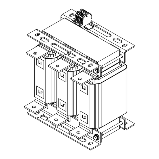
The filter consists of separate inductors and capacitor banks. The components are delivered separately.
Figure 1: Items Included in the Delivery
Danfoss Drives Oy © 2024.03
Description
This part is same for all the products.
Filter type:
• LCL filter
• LC filter
The current rating in amperes. For example, 0525 = 525 A
The mains voltage:
• 5 = 380–500 V
The protection rating:
• 0 = IP00
Cooling method:
• AF = Forced air cooling
Temperature measurement type:
• TP = Thermal relay and Pt100 temperature sensor
AN477036797705en-000101 / 172K2871A |
1
Advertisement
Table of Contents

Related Manuals for Danfoss VACON SISO LCL


Summary of Contents for Danfoss VACON SISO LCL
- Page 1 • TP = Thermal relay and Pt100 temperature sensor Contents of the Delivery The filter consists of separate inductors and capacitor banks. The components are delivered separately. Figure 1: Items Included in the Delivery Danfoss Drives Oy © 2024.03 AN477036797705en-000101 / 172K2871A |...
-
Page 2: Mechanical Installation
The personnel involved in the operation and maintenance of this filter must be aware of the necessary safety precautions for this type of equipment because of the high voltages required by the application. | Danfoss Drives Oy © 2024.03 AN477036797705en-000101 / 172K2871A... -
Page 3: Installation Requirements
The minimum airflow is 3 m/s (10 ft/s). Install air guides or ducts to guide the hot air from the inductors up, away from other components, and out of the enclosure. Danfoss Drives Oy © 2024.03 AN477036797705en-000101 / 172K2871A |... -
Page 4: Electrical Installation
The C capacitor is optional and not included in the delivery by default. The C capacitor is typically used in grounded networks, bypassing the excess high frequency noise from the load side. For further information, contact Danfoss. L1’ L1’ DC+’... - Page 5 The ground terminal size on the inductors is Ø11 mm (0.43 in). Use tightening torque 55 Nm (486 in-lb). The ground terminal size on the capacitor banks is M10. Use tightening torque 55 Nm (486 in-lb). See the terminal locations in Terminals. Danfoss Drives Oy © 2024.03 AN477036797705en-000101 / 172K2871A |...
- Page 6 L1, L2, L3 Drive AC L1' , L2' , L3' Drive DC +DC' , -DC' +DC, -DC Figure 5: Terminals on the Drive Side Inductor Figure 6: Terminals on the Grid Side Inductor | Danfoss Drives Oy © 2024.03 AN477036797705en-000101 / 172K2871A...
-
Page 7: Over Temperature Protection
Connect the sensor for DC windings to terminals 4.1 and 4.2. If the grid side inductor is included in the delivery, install the thermal relay and Pt100 temperature sensor wires to it. Danfoss Drives Oy © 2024.03 AN477036797705en-000101 / 172K2871A |... -
Page 8: Specifications
Protection level IP00 Pollution degree 3, IEC60664-1 Installation altitude < 1000 m (3280 ft) above sea-level without derating Standards EN 61558-2-20, IEC 61800-5-1, UL 61800-5-1, REACH, RoHS (2011/65/EU + 2015/863), IEC 62474 | Danfoss Drives Oy © 2024.03 AN477036797705en-000101 / 172K2871A... - Page 9 Installation Guide | SISO LCL and LC Filters Dimensions Figure 9: Dimensions of the Drive Side Inductor in mm (in) Figure 10: Dimensions of the Grid Side Inductor in mm (in) Danfoss Drives Oy © 2024.03 AN477036797705en-000101 / 172K2871A |...
-
Page 10: Maintenance
These conditions can include, for example, extreme temperature, dust, high humidity, hours of use, corrosive environment, and loading. For operation in stressful conditions, Danfoss offers the DrivePro® Preventive Maintenance service. DrivePro® services extend the lifetime and increase the performance of the product with scheduled maintenance including customized part replacements. DrivePro® services are tailored to your application and operating conditions. - Page 11 2) Defined as the time after the commissioning/start-up or the time from the previous service schedule actions. Recommended Disposal When the product reaches the end of its service life, its primary components can be recycled. Danfoss Drives Oy © 2024.03 AN477036797705en-000101 / 172K2871A |...
- Page 12 Danfoss reserves the right to alter its products without notice. This also applies to products ordered but not delivered provided that such alterations can be made without changes to form, fit or function of the product. All trademarks in this material are property of Danfoss A/S or Danfoss group companies.
Need help?
Do you have a question about the VACON SISO LCL and is the answer not in the manual?
Questions and answers