Table of Contents
Advertisement
Quick Links
Instruction Manual book
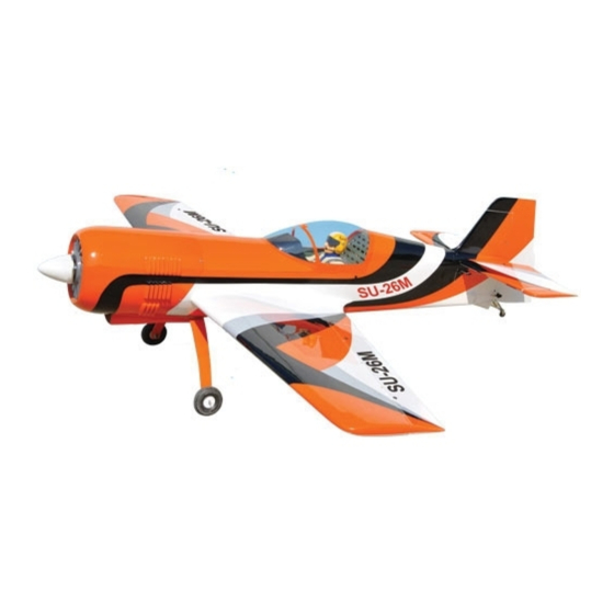
SPECIFICATION
Wingspan :
Length
Weight
Radio :
Servo :
Glow Engine : OSGT 55- 62cc gas.
2,240mm.
: 1,950 mm.
:
8.5kg.
8 channels.
8 servos.
(JR DS: 8321-FUTABA: BLS252).
ITEM CODE: BH96.
88.19 in.
76.77 in.
18.7 lbs.
Made in Vietnam.
Advertisement
Table of Contents

Related Manuals for Black Horse Model SU-26M


Summary of Contents for Black Horse Model SU-26M
- Page 1 Instruction Manual book ITEM CODE: BH96. SPECIFICATION Wingspan : 2,240mm. 88.19 in. Length : 1,950 mm. 76.77 in. Weight 8.5kg. 18.7 lbs. Radio : 8 channels.
-
Page 2: Parts List
Instruction Manual ITEM CODE: BH96. This instruction manual is designed to help you build a great flying aeroplane. Please read this manual thoroughly before starting assembly of your SU-26M. Use the parts listing below to identify all parts. WARNING. Please be aware that this aeroplane is not a toy and if assembled or used incorrectly it is capable of causing injury to people or property. -
Page 3: Safety Precaution
SU-26M - Instruction Manual ITEM CODE: BH96. Caution: this model is not a toy! Caution! do not heat the film more than is absolutely necessary. If the air or the iron is If you are a beginner to this type of powered... - Page 4 SU-26M - Instruction Manual ITEM CODE: BH96. REPLACEMENT SMALL PARTS 1. Aluminium landing gear. INSTALLING THE AILERON SERVOS 1. 2. Wheels. 1. Install the rubber grommets and brass eyelets onto the aileron servo. 3. Plastic parts for rudder pushrod.
- Page 5 SU-26M - Instruction Manual ITEM CODE: BH96. 2 x 12 mm. Servo tray. Secure. Repeat the procedure for the other wing half. Secure. INSTALLING THE AILERON CONTROL HORN 1 3. Using the thread as a guide and using masking tape, tape the servo lead to the end of the thread: carefully pull the thread out.
-
Page 6: Installing The Aileron Servos
SU-26M - Instruction Manual ITEM CODE: BH96. INSTALLING THE AILERON SERVOS 2. INSTALLING THE AILERON LINKAGES 1. Installing the aileron linkages as pictures below. 96 mm 3x15mm Attach the clevis to the outer hole in the con- trol horn. Secure 2 x 12 mm. -
Page 7: Installing The Aileron Linkages
SU-26M - Instruction Manual ITEM CODE: BH96. Bottom side. Repeat the procedure for the other wing half. MAIN GEAR INSTALATION. PARTS REQUIRED 1. Assemble and mounting the wheel pants as shown in the following pictures. Elevator control horn 2. -
Page 8: Installing The Engine Mount
SU-26M - Instruction Manual ITEM CODE: BH96. INSTALLING THE ENGINE MOUNT. See pictures below: Secure Drill a hole 6mm diameter. Secure FUEL TANK. INSTALLING THE STOPPER ASSEMBLY 1. The stopper has been pre-assembled at the factory. Bottom side ... - Page 9 SU-26M - Instruction Manual ITEM CODE: BH96. 4. Carefully bend the third nylon tube down 6. When satisfied with the alignment of the at a 45 degree angle (using a cigarette lighter). stopper assembly tighten the 3mm x 20mm This tube will be vent tube to the fueling valve.
- Page 10 SU-26M - Instruction Manual ITEM CODE: BH96. Do not secure the tank into place perma- INSTALLING THE ENGINE- nently until after balancing the airplane. THROTTLE. You may need to remove the tank to mount the battery in the fuel tank compartment.
-
Page 11: Installing The Throttle - Cable
SU-26M - Instruction Manual ITEM CODE: BH96. Secure Right side. Right side. INSTALLING THE THROTTLE - CABLE. Tie wrap. 1. Install one adjustable metal connector through the third hole out from the center of one servo arm, enlarge the hole in the servo arm using a 2mm drill bit to accommodate the servo connector. - Page 12 SU-26M - Instruction Manual ITEM CODE: BH96. COWLING. Throttle - cable 1. Slide the fiberglass cowl over the en- gine and line up the back edge of the cowl with the marks you made on the fuselage. Top side Bottom side.
-
Page 13: Installing The Spinner
SU-26M - Instruction Manual ITEM CODE: BH96. Trim and cut. Front view. Trim and cut. INSTALLING THE SPINNER. Install the spinner backplate, propeller and spinner cone. The spinner cone is held in place using two 3mm x 8mm machine screws. -
Page 14: Installing The Elevator Servos
SU-26M - Instruction Manual ITEM CODE: BH96. Secure INSTALLING THE ELEVATOR HORIZONTAL STABILIZER. SERVOS. Horizontal stabilizer installation See picture below. 1. Install the rubber grommets and brass collets into the elevator servo. Test fit the servo into the servo tray. -
Page 15: Elevator Control Horn Installation
SU-26M - Instruction Manual ITEM CODE: BH96. ELEVATOR CONTROL HORN INSTALLATION. Elevator control horn install as same as the way of aileron control horn. Please see pic- tures below. 3 x 25 mm. 3 x 15mm Elevator control horn. Secure ELEVATOR PUSHROD INSTALLATION. -
Page 16: Mounting The Tail Wheel Bracket
SU-26M - Instruction Manual ITEM CODE: BH96. Secure MOUNTING THE TAIL WHEEL BRACKET. 3x12mm 3x15mm Elevator Elevator Pushrod Pushrod Secure VERTICAL INSTALLATION. Rudder servo install as same as method of elevator servo. See picture below:... - Page 17 SU-26M - Instruction Manual ITEM CODE: BH96. 3x15mm Drill a hole 3mm diameter A+B Epoxy Plus glue. Secure Top side.
-
Page 18: Rudder Pushrod Installation
SU-26M - Instruction Manual ITEM CODE: BH96. RUDDER PUSHROD INSTALLATION. 1. Rudder push - pull system install as same as picture below. 3 x 15mm Bottom side. RUDDER CONTROL HORN INSTALLA- TION. Secure Rudder control horn install as same as the way of aileron control horn. -
Page 19: Installing The Receiver And Battery
SU-26M - Instruction Manual ITEM CODE: BH96. UBEC. INSTALLING THE RECEIVER AND BATTERY. 1. Plug the servo leads and the switch lead into the receiver. You may want to plug an aileron extension into the receiver to make... -
Page 20: Wing Attachment
SU-26M - Instruction Manual ITEM CODE: BH96. Wing bolt. Receiver Wing bolt. UBEC. WING ATTACHMENT. Locate the aluminium wing dihedral brace. 1,070 mm Right wing. 880 mm Drill a hole *** Test fit the aluminium tube dihedral brace 3mm diameter into each wing haft. - Page 21 SU-26M - Instruction Manual ITEM CODE: BH96. Secure. Top side. Plastic part bottom side fuselage Drill a hole 3mm diameter Left wing. Secure Cut.
- Page 22 SU-26M - Instruction Manual ITEM CODE: BH96. C/A glue Plastic part for tail gear. C/A glue Plastic parts of rudder pushrod. Mark point Cut. R e m o v e covering...
-
Page 23: Control Throws
SU-26M - Instruction Manual ITEM CODE: BH96. Lift the model. If the tail drops when you lift, the model is “tail heavy” and you must add weigh* to the nose. If the nose drops, it is “nose heavy” and you must add weight* to the tail to C/A glue balance. -
Page 24: Pre-Flight Check
5. Check the receiver antenna . It should be fully extended and not coiled up inside the fuselage. 6. Properly balance the propeller. We wish you many safe and enjoy- able flights with your SU-26M...
Need help?
Do you have a question about the SU-26M and is the answer not in the manual?
Questions and answers