Salda Ptouch Service Manual
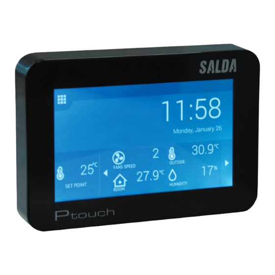
Remote control panel
Source: salda.lt/en, vetter-lufttechnik.de
Hide thumbs
Also See for Ptouch:
- Service manual (19 pages) ,
- User manual (111 pages) ,
- User manual (21 pages)

Related Manuals for Salda Ptouch


Summary of Contents for Salda Ptouch
- Page 1 • Remote control panel Ptouch Service manual Ragainės g. 100, LT-78109 Šiauliai, Lithuania Tel. (+370 41) 540415 Art.-no. PRGPU081 Fax. (+370 41) 540417 office@salda.lt MCB_P0096_AZ_0001 www.salda.lt...
-
Page 2: Table Of Contents
TABLE OF 1. GENERAL INFORMATION ....................4 CONTENTS 2. DIMENSIONS ..........................4 3. INSTALLATION ........................5 4. SERVICE ............................6 4.1. Service login ........................6 4.2. Service menu ........................6 4.3. Main settings menu ....................... 8 4.3.1. System blocking settings ................... 9 5. AIR TEMPERATURE CONTROL SETTINGS ..............10 6. AIR TEMPERATURE PROTECTION SETTINGS ............11 7. SYSTEM MODE SWITCH SETTINGS ................12 8. FAN SPEED SWITCH SETTINGS ..................13 9. AIR FILTER PROTECTION SETTINGS ................. - Page 3 19. HEAT EXCHANGER SETTINGS ..................25 20. HEATER SETTINGS ......................26 20.1. Supplied air heater settings ................... 26 21. FRESH AIR PRE-HEATER SETTINGS ................. 27 22. ELECTRICAL HEATERS COOLING SETTINGS ............28 23. HYDRAULIC HEATER PROTECTION ................. 29 24. COOLER SETTINGS ......................30 25. DIGITAL INPUT SETTINGS .................... 31 25.1. External control input settings ................32 26. FAN PROTECTION INPUT SETTINGS ............... 33 27. HEATER PROTECTION INPUT SETTINGS ............... 34 28. COOLER PROTECTION INPUT SETTINGS .............. 35 29. FILTER PRESSURE RELAY INPUT SETTINGS ............35 30. FIRE DAMPER SWITCH INPUT SETTINGS ............. 36 31. BYPASS SWITCH INPUT SETTINGS ................37 32. SENSOR SETTINGS ......................
-
Page 4: Table Of 1. General Information
1. GENERAL INFORMATION Ptouch remote control panel is designed for: • SALDA ventilation units and other devices based on PRV, MCB or ECO controllers; • Modbus-controlled devices. Remote control panels guarantee optimal comfort of operation, monitoring, maintenance and service. All operations can be performed using remote panel, which displays the status of the system, fault reports and service settings. -
Page 5: Installation
3. Ptouch installation on a plaster-board wall: Ptouch installation on a plaster-board wall: IMPORTANT: IT IS FORBID- DEN to leave the remaining remote controller’s cable in the AHU’s control box! 1-2 Turn over the panel. Use a screwdriver to lift the cover as shown in fig. 2. 3 Take the cover apart. 4 Put it at desired location on the wall. The arrow must point upwards. Mark the positions of mounting holes (distance center-to-center is 106 ±... -
Page 6: Service
4. SERVICE 4.1. Service login Number Function Entered code (masked) 2200 Number Function Clear last entered digit Confirm entered code 4.2. Service menu... - Page 7 Number Function Main settings. Fan settings. Damper settings. Heat exchanger settings. Heater settings. Cooler settings. Digital input settings. Sensor settings. Communication settings.
-
Page 8: Main Settings Menu
4.3. Main settings menu Number Function System blocking settings. Air temperature control settings. Air temperature protection settings. System mode switch settings. Fan speed settings. Air filter protection settings. Fire protection settings. Controller box heating settings. Fans speed switch settings. Air filters protections settings. -
Page 9: System Blocking Settings
Fire protection settings. Controller box heating settings. CO2 reduction settings. 4.3.1. System blocking settings Number Function Current setting indication. Number Function Block automatic control: Auto: automatic control is enabled; Block: automatic control is disabled. Standby blocking mode: Never: standby is allowed; Always: standby is not allowed; Heating season: standby is prohibited during heating season;... -
Page 10: Air Temperature Control Settings
5. AIR TEMPERATURE CONTROL SETTINGS Number Function Current setting indication. Number Function Temperature control type: By supply air: supplied air temperature is equal to set desired temperature; Extract (room) air: supplied air temperature is variable and includes supply temperature compensation. Supply temperature compensation. Only available if temperature con- trol type is “extract (room) air”. -
Page 11: Air Temperature Protection Settings
6. AIR TEMPERATURE PROTECTION SETTINGS Number Function Current setting indication. Number Function Supply temperature low limit (in °C * 10). Protects from supplying too cold air. Range: [0-200 °C] (0-20.0 °C) Supply temperature high limit (in °C * 10). Protects from supplying too hot air. Range: [200-600 °C] (20.0-60.0 °C) Supply temperature limit timeout. -
Page 12: System Mode Switch Settings
7. SYSTEM MODE SWITCH SETTINGS Number Function Current setting indication. Number Function Remote switch type: None: no remote switch; Push: push-button type switch; On/Off: normal switch; PIR: passive infrared sensor. Mode selected using the remote switch: Standby; Building protection; Economy; Comfort. -
Page 13: Fan Speed Switch Settings
8. FAN SPEED SWITCH SETTINGS Number Function Current setting indication. Number Function Remote switch type: None: no remote switch; CUSTOM Push: push-button type switch for enabling custom fan speeds; CUSTOM On/Off: normal switch for enabling custom fan speeds; BOOST Push: push-button type switch for operating fans at their maximum speeds;... -
Page 14: Air Filter Protection Settings
9. AIR FILTER PROTECTION SETTINGS Number Function Current setting indication. Number Function Filters press relay type: None: no pressure relays for filter-contamination detection; Supply: one pressure relay in supplied air duct; Extract: one pressure relay in extracted air duct; Both: two pressure relays. Number of days between filter replacements. Range: [0-365 d.]... -
Page 15: Fire Protection Settings
10. FIRE PROTECTION SETTINGS Number Function Current setting indication. Number Function Fire protection action: Stop system: fans are stopped, alert is risen; Boost supply air: supply fan is operated at full speed, extract fan is stopped; Boost extract air: supply fan is stopped, extract fan is operated at full speed;... -
Page 16: Controler Box Heating Settings
11. CONTROLER BOX HEATING SETTINGS Number Function Current setting indication. Number Function AHU Control box heating: Enabled; Disabled. Control box heating temperature set point. Range: [0-20 °C]... -
Page 17: Co2 Reduction Settings
12. CO2 REDUCTION SETTINGS Number Function Current setting indication. Number Function CO2 Level protection: Enabled; Disabled. Optimal CO2 level. Range: [0-1000 ppm] Allowed CO2 level range around the desired CO2 level. Range: [0-1000 ppm]... -
Page 18: Fan Settings
13. FAN SETTINGS Number Function Fan speed settings. Fan voltage settings. Fan protection settings. 13.1. Fan speed control settings... - Page 19 Number Function Current setting indication Number Function Control using fixed fan speeds: Yes: use operating modes; No: use control by speed. Fans control type: Percent’s: control linearly by voltage (within specified minimum and maximum voltages); Pressure: control using pressure sensor signals (using maximum air pressure setting);...
-
Page 20: Fan Voltage Settings
Number Function Maximum air flow pressure (when Fan control type is Pressure). Range: [0-1000 Pa] 14. FAN VOLTAGE SETTINGS Number Function Current setting indication. Number Function Minimal fan voltage (in V/100). Used as a limiting value. Range: [0-1000] (0-10.00 V) Maximal supply fan voltage (in V/100). Used as a limiting value or (when Fan control type is Percent’s) as maximum air flow level. -
Page 21: Fan Protection Settings
15. FAN PROTECTION SETTINGS Number Function Current setting indication Number Function Halted fan protection by monitoring its speed: Enabled: alert is risen and system is stopped if after fan start signal its speed remains 0 rpm for at least 10 s; Disabled: fan speed monitoring is off. Halted fan protection by monitoring duct pressure: Enabled: alert is risen and system is stopped if pressure in a duct does not increase after fan start;... -
Page 22: Damper Settings
16. DAMPER SETTINGS Number Function Supply/extract damper settings. Recirculation damper settings. Fire damper settings. 16.1. Supply/extract damper settings... -
Page 23: Recirculation Damper Settings
Number Function Current setting indication. Number Function Supply/extract damper type: None; On/off: one-terminal controlled damper. Closes mechanically if no signal is provided; OpenClose: two-terminal controlled damper. Stays still if no signal is provided. Can be opened or closed partially. Time required for supply/extract damper to fully open (in seconds). Range: [0-255 s] 17. RECIRCULATION DAMPER SETTINGS Number... -
Page 24: Fire Damper Settings
18. FIRE DAMPER SETTINGs Number Function Current setting indication Number Function Fire damper type: None; One switch; Two switches. Time required for fire damper to fully open (in seconds). Range: [0-255 s] Fire damper testing: Enabled; Disabled. Fire damper testing interval (in days). Range: [0-130 days] Fire damper action on fire alarm: Open;... -
Page 25: Heat Exchanger Settings
19. HEAT EXCHANGER SETTINGS Number Function Current setting indication. Number Function Heat exchanger type: None; Plate; Rotor. Plate heat exchanger frost protection strategy: None; Pre-heating by set point; Pre-heating by frost point; Recirculating by set point; Recirculating by frost point. Set point (as a difference from frost point). Range: [-30-10 °C]... -
Page 26: Heater Settings
20. HEATER SETTINGS Number Function Supplied air heater settings. Fresh air pre-heater settings. Electrical heaters cooling settings. Hydraulic heater protection. 19.1. Supplied air heater settings... -
Page 27: Fresh Air Pre-Heater Settings
Number Function Current setting indication. Number Function Supplied air heater type: None; Electrical 0-10VDC; Electrical on/off; Hydraulic. Electrical pre-heater PWM time interval (if pre-heater type is Electri- cal on/off). Range: [0-300 s] Alarm overheat action: None; Stop system; Intensive ventilation. 21. FRESH AIR PRE-HEATER SETTINGS Number Function... -
Page 28: Electrical Heaters Cooling Settings
Number Function Fresh air pre-heater type: None; Electrical 0-10VDC; Electrical on/off; Hydraulic. Electrical pre-heater PWM time interval (if pre-heater type is Electri- cal on/off). Range: [0-300 s] Alarm overheat action: None; Stop system; Intensive ventilation. 22. ELECTRICAL HEATERS COOLING SETTINGS Number Function Current setting indication. Number Function Electrical heating components cooling time. -
Page 29: Hydraulic Heater Protection
23. HYDRAULIC HEATER PROTECTION Number Function Current setting indication. Number Function Hydraulic heating components preparation time. Fluid heating time before initial fan start (during heating season). Range: [0-100 s] Hydraulic heater frost temperature. In a case of lower supplied air temperature, system is stopped. Range: [-30-10 °C] Water temperature low limit. -
Page 30: Cooler Settings
24. COOLER SETTINGS Number Function Current setting indication Number Function Hydraulic cooler: Enabled; Disabled. Hydraulic cooler frost temperature. In a case of lower supplied air temperature, system is stopped. Range: [-30-10 °C] DX cooler: Enabled; Disabled. DX cooler minimum off time. Range: [1-30 min]... -
Page 31: Digital Input Settings
25. DIGITAL INPUT SETTINGS Number Function External control input settings. Fan protection input settings. Heater protection input settings. Cooler protection input settings. Filter pressure relay settings. Fire damper switch input settings. Bypass switch input settings. -
Page 32: External Control Input Settings
25.1. External control input settings Number Function Current setting indication Number Function Fire protection input: NO: normally open; NC: normally closed. System mode switch input: NO: normally open; NC: normally closed. Fan speed switch input: NO: normally open; NC: normally closed. -
Page 33: Fan Protection Input Settings
26. FAN PROTECTION INPUT SETTINGS Number Function Current setting indication. Number Function Supply fan protection input: NO: normally open; NC: normally closed. Extract fan protection input: NO: normally open; NC: normally closed. -
Page 34: Heater Protection Input Settings
27. HEATER PROTECTION INPUT SETTINGS Number Function Current setting indication Number Function Heater manual protection input: NO: normally open; NC: normally closed. Heater automatic protection input: NO: normally open; NC: normally closed. Pre-heater manual protection input: NO: normally open; NC: normally closed. Pre-heater automatic protection input: NO: normally open;... -
Page 35: Cooler Protection Input Settings
28. COOLER PROTECTION INPUT SETTINGS Number Function Current setting indication. Number Function DX cooler protection input: NO: normally open; NC: normally closed. 29. FILTER PRESSURE RELAY INPUT SETTINGS... -
Page 36: Fire Damper Switch Input Settings
Number Function Current setting indication. Number Function Supply filter pressure relay input: NO: normally open; NC: normally closed. Extract filter pressure relay input: NO: normally open; NC: normally closed. 30. FIRE DAMPER SWITCH INPUT SETTINGS Number Function Current setting indication. Number Function Fire damper opened input: NO: normally open;... -
Page 37: Bypass Switch Input Settings
31. BYPASS SWITCH INPUT SETTINGS Number Function Current setting indication. Number Function Bypass opened input: NO: normally open; NC: normally closed. Bypass closed input: NO: normally open; NC: normally closed. 32. SENSOR SETTINGS... -
Page 38: 0-10Vdc Sensor Settings
Number Function 0-10VDC sensor settings. Temperature sensor settings. 32.1. 0-10VDC sensor settings Number Function Supplied air quality sensor settings. Extracted air quality sensor settings. 33. SUPPLIED AIR QUALITY SENSOR SETTINGS... -
Page 39: Extracted Air Quality Sensor Settings
Number Function Current setting indication Number Function Supplied air quality sensor type: None; RH: Relative humidity sensor; CO2: Carbon dioxide sensor. CO2 level (in ppm) at minimum voltage (0 VDC). Range: [0-2000 ppm] CO2 level (in ppm) at maximum voltage (10 VDC). Range: [0-2000 ppm] 34. EXTRACTED AIR QUALITY SENSOR SETTINGS Number... -
Page 40: Temperature Sensor Settings
35. TEMPERATURE SENSOR SETTINGS Number Function Supplied air temperature sensor settings. Extracted air temperature sensor settings. Exhausted air temperature sensor settings. Outdoor air temperature sensor settings. Hydraulic heater water temperature sensor settings. Hydraulic pre-heater water temperature sensor settings. Hydraulic cooler water temperature sensor settings. Control box temperature sensor settings. - Page 41 NOTE: This screen is applicable for all temperature sensor settings. Number Function Current setting indication. Number Function Temperature sensor type: None; Remote: temperature values are received over communication interface (using Modbus); NTC 3997: thermo-resistive sensor. Temperature sensor alarm (activated if temperature sensor value is less than -50 °C or more than +50 °C): None;...
-
Page 42: Communication Settings
36. COMMUNICATION SETTINGS Number Function Internal Modbus port settings. BMS Modbus port settings. 36.1. Internal modbus port settings Number Function Current setting indication... -
Page 43: Bms Modbus Port Settings
Number Function AHU Control unit Modbus address. Range: [1-247] Baud rate: 1200; 2400; 4800; 9600; 19200; 38400; 57600; 115200. Frame settings: N-8-1: No parity – 8 data bits – 1 stop bit; E-8-1: Even parity – 8 data bits – 1 stop bit; O-8-1: Odd parity –... - Page 44 Frame settings: N-8-1: No parity – 8 data bits – 1 stop bit; E-8-1: Even parity – 8 data bits – 1 stop bit; O-8-1: Odd parity – 8 data bits – 1 stop bit; N-8-2: No parity – 8 data bits – 2 stop bits; E-8-2: Even parity –...
Need help?
Do you have a question about the Ptouch and is the answer not in the manual?
Questions and answers