Table of Contents
Advertisement
Quick Links
Advertisement
Table of Contents

Related Manuals for Fujitsu Siemens Computers PRIMERGY BX600 S2


Summary of Contents for Fujitsu Siemens Computers PRIMERGY BX600 S2
-
Page 1: Primergy Bx600 S2 Basic Unit
PRIMERGY BX600 S2 Basic Unit Operating Manual Edition March 2007... -
Page 2: Copyright And Trademarks
Gesellschaft für Technik-Dokumentation mbH www.cognitas.de Copyright and Trademarks Copyright © 2007 Fujitsu Siemens Computers GmbH. All rights reserved. Delivery subject to availability; right of technical modifications reserved. All hardware and software names used are trademarks of their respective manufacturers. -
Page 3: Table Of Contents
Cable Routing ......43 4.4.2 Instructions on Connecting and Disconnecting Cables ..45 Connecting the System to the Mains ... . . 46 PRIMERGY BX600 S2 Basic Unit... - Page 4 Port Assignment of the LAN Switch Blades ..90 Installing a LAN Switch Blade ....93 PRIMERGY BX600 S2 Basic Unit...
- Page 5 Adv. KVM Blade ......135 13.3 Digital KVM Blade ..... . . 137 PRIMERGY BX600 S2 Basic Unit...
- Page 6 ........169 PRIMERGY BX600 S2 Basic Unit...
-
Page 7: Introduction
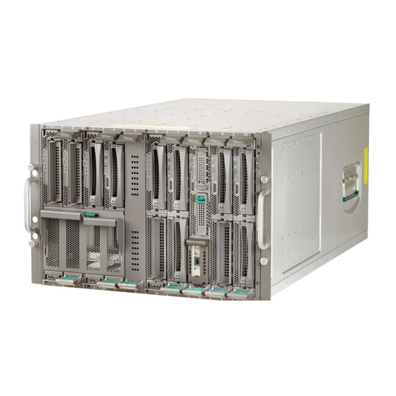
19-inch rack systems. Figure 1: PRIMERGY BX600 S2 Basic Unit The PRIMERGY BX600 S2 basic unit occupies seven height units in the rack and can accommodate up to ten server blades of different models and configu- rations. -
Page 8: Overview Of The Documentation
This operating manual is intended for those responsible for installing the hardware and operating the system. The manual contains all the information required for mounting and operating your PRIMERGY BX600 S2 basic unit. For a brief overview of the installation steps please see chapter 2 on page 19ff. - Page 9 – the ServerView Server Management manual – the manual for the Remote Test and Diagnostic System RemoteView – your operating system documentation – the information files of your operating system (see also “Related Publications” on page 165). PRIMERGY BX600 S2 Basic Unit...
-
Page 10: Features
165. Communication interfaces The PRIMERGY BX600 S2 basic unit has four slots on the back for installing different types of communication blades which allow the installed server blades to be connected to the Ethernet LAN or to SAN environments. The connections can be implemented via switch blades and/or pass-thru blades. - Page 11 The Ethernet LAN Pass-Thru-Blade has ten RJ45 connectors. Fibre Channel pass-thru blade The PRIMERGY BX600 S2 basic unit can have one or two Fibre Channel pass-thru blades to provide Fibre Channel functionality for the installed server blades. A Fibre Channel (FC) pass-thru blade offers 10 ports for bypass connections between FC daughter cards installed in the server blades and the optical transceivers for serial FC I/O and general I/O signals.
- Page 12 Features Introduction KVM-Blade For administering the server blades, the PRIMERGY BX600 S2 basic unit offers a KVM blade, which allows the individual server blades to be connected to a console. – The standard KVM blade allows a monitor, PS2 keyboard and PS2 mouse to be connected for local administration of the server blades.
- Page 13 PRIMERGY servers are service-friendly and modular, thus allowing quick and easy maintenance. For easy and immediate recognition, the levers or handles and locking buttons (touch points) of the locking mechanisms for the different compo- nents have the color green. PRIMERGY BX600 S2 Basic Unit...
-
Page 14: Notational Conventions
Pay particular attention to text marked with this symbol. Failure to observe this warning may endanger your life, damage the server, or lead to loss of data. This symbol introduces supplementary information, remarks and tips. Table 1: Notational conventions PRIMERGY BX600 S2 Basic Unit... -
Page 15: Technical Data
Electromagnetic compatibility FCC class A Emitted interference EN 55022 class A Harmonic current EN 61000-3-2 Noise immunity EN 55024 CE label Low-Voltage Directive 73/23/EEC according to EU directives Electromagnetic Compatibility 89/336/EEC Certification Product safety Global PRIMERGY BX600 S2 Basic Unit... - Page 16 Technical Data Introduction Europe ENEC Germany USA/Canada / CSA Japan VCCI Mechanical Values Width 446 mm Installation depth 740 mm Height 307 mm oder 7 HE Weight max. 131.5 kg (depending on the configuration) PRIMERGY BX600 S2 Basic Unit...
- Page 17 -20 °C ..60 °C Relative humidity 10%...85% Condensation during operation must be avoided. Noise Level Sound power level L (ISO 7779) 7.8 BA ≤ 59 dB(A) (in the Sound pressure level at bystander position (ISO 9296) standard configuration) PRIMERGY BX600 S2 Basic Unit...
-
Page 19: Overview: Basic Unit Installation Steps
– Cloning a server blade from a remote image server with RemoteDeploy Recommended if the following requirements are satisfied: – the RemoteDeploy software is available – an appropriate cloning image is available – deployment server and LAN connection are available PRIMERGY BX600 S2 Basic Unit... - Page 20 BX600 S2 basic unit. A PDF version of the manual is contained on the PRIMERGY ServerBooks DVD. Cloning of server blades is described in the RemoteDeploy manual (print version delivered with RemoteDeploy, PDF version contained on the PRIMERGY ServerBooks DVD). PRIMERGY BX600 S2 Basic Unit...
-
Page 21: Important Notes
If you have any questions, please contact your sales outlet or the customer service center of Fujitsu Siemens Computers. CAUTION! The actions described in these instructions should only be performed by technicians, service personnel or technical specialists. - Page 22 (public) power supply networks for the type-A connector. For the PRIMERGY BX600 S2 basic unit only 2100W PSUs are allowed (Product no. A3C40073262)! The 1200W PSUs of the PRIMERGY BX600 S1 basic unit is not allowed for the PRIMERGY BX600 S2 basic unit.
- Page 23 Important Notes Notes on Safety Make sure that the PRIMERGY BX600 S2 basic unit is connected to the mains for at least one minute before pressing the power ON/OFF button to switch the system ON. CAUTION! The server automatically adjusts to a mains voltage of 200 - 240 V.
- Page 24 Hg Mercury Pb Lead Other Important Notes: Keep this operating manual and all additional documentation together with the device. If you pass on the device to third parties, you should also pass on the complete documentation. PRIMERGY BX600 S2 Basic Unit...
-
Page 25: Components With Electrostatic-Sensitive Devices
ANSI/ESD S20.20). CE Certificate The shipped version of this device complies with the requirements of the EEC directives 89/336/EEC “Electromagnetic compatibility” and 73/23/EEC “Low voltage directive”. The device therefore qualifies for the CE certificate (CE=Communauté Européenne). PRIMERGY BX600 S2 Basic Unit... -
Page 26: Fcc Class A Compliance Statement
Consult the dealer or an experienced radio/TV technician for help. Fujitsu Siemens Computers is not responsible for any radio or television inter- ference caused by unauthorized modifications of this equipment or the substi- tution or attachment of connecting cables and equipment other than those specified by Fujitsu Siemens Computers. -
Page 27: Transporting The Basic Unit
Transporting the Basic Unit CAUTION! Transport the PRIMERGY BX600 S2 basic unit only in its original packaging or in a packaging which protects it from knocks and jolts. Do not unpack the basic unit until you have finished transporting it. -
Page 28: Notes On Installing In The Rack
(public) power supply protection must comply with the requirements for the non-industrial (public) power supply networks for the type-A connector. The power supply for the rack should be divided amongst the three phases of a three-phase power connection. PRIMERGY BX600 S2 Basic Unit... -
Page 29: Environmental Protection
(see also “Returning Batteries” on page 31). Notes on Labeling Plastic Housing Parts Please avoid attaching your own labels to plastic housing parts wherever possible, since this makes it difficult to recycle them. PRIMERGY BX600 S2 Basic Unit... - Page 30 – Meaning of the symbol "Crossed out rubbish bin on wheels" Electrical (electronic) devices which are marked with one of the following symbols may not be disposed of with household refuse in accordance with the EU directive. Figure 3: Symbols for electrical (electronic) devices PRIMERGY BX600 S2 Basic Unit...
- Page 31 Local Contacts For details on take-back and reuse of devices and consumables within Europe, contact your Fujitsu Siemens Computers branch office/subsidiary or our recycling centre in Paderborn: Fujitsu Siemens Computers...
-
Page 33: Installing The Hardware
CAUTION! Please note the safety instructions in the chapter “Important Notes” on page Do not expose the PRIMERGY BX600 S2 basic unit to extreme environ- mental conditions (see section “Technical Data” on page 15). Protect it from dust, moisture, and heat. -
Page 34: Unpacking The Basic Unit
Please note the safety instructions in the chapter “Important Notes” on page Do not unpack the PRIMERGY BX600 S2 basic unit until you have finished transporting it. We recommend that you do not throw away the original packaging material! It may be required for future transportation. -
Page 35: Installing The System In The Rack
Installing the System in the Rack CAUTION! For safety reasons, at least two people are required to install the PRIMERGY BX600 S2 basic unit because of its weight and size. Please observe the safety precautions and references to rack instal- lation in the chapter “Important Notes”... - Page 36 The rails have with a linear alignment option to also allow adjustment to different rack depths. – No support for the cable management delivered with the mounting kit. This cable management is customized for the Fujitsu Siemens Computers PRIMECENTER rack. – Climatic conditions.
- Page 37 (air flow from the front to the rear). – Power supply. For installation in 3rd-party racks, you must ensure that appropriate socket strips are present. Figure 5: Mechanical conditions PRIMERGY BX600 S2 Basic Unit...
-
Page 38: Mounting The Assembly Kit
“Related Publications” on page 165). To mount the PRIMERGY BX600 S2 basic unit in the rack, you must first mount two support brackets on the rear left support upright of the rack. The first one must be mounted level with the lower edge of the device, while the second must be mounted level with the upper edge of the first. - Page 39 Ê Pull the carrier rail of the rack-mounting kit forward as far as possible in the direction of the arrow (2). Ê Fasten the six screws for adjusting the rail length (1). Ê Repeat the procedure for the second rail. Note that for this rail no support bracket is necessary. PRIMERGY BX600 S2 Basic Unit...
-
Page 40: Mounting/Removing The Basic Unit
Mounting/Removing the Basic Unit CAUTION! For safety reasons, at least two people are required to mount or remove the PRIMERGY BX600 S2 basic unit because of its weight and size. Please note the relevant safety instructions in section “Notes on Installing in the Rack”... -
Page 41: Connecting External Devices
Ê Pull out the basic unit and carefully remove it from the rack. Connecting External Devices The external connectors of the PRIMERGY BX600 S2 basic unit are located on the rear of the basic unit. The external connectors of the server blades are located on the front of the basic unit. - Page 42 KVM connector on rear KVM blade, which offers VGA, PS2 keyboard and mouse support via a special cable (see figure 10 below). The Adv. KVM bladeand the digital KVM blade also offers a LAN connectors (RJ45, 10 Mb) (see also figure 85 on page 134). PRIMERGY BX600 S2 Basic Unit...
-
Page 43: Cable Routing
11 below. You may also route the cable to the back of the rack, using the space below the basic unit. PRIMERGY BX600 S2 Basic Unit... - Page 44 SCSI cable. The curved design of the PRIMECENTER rack door ensures that there is sufficient room for slots 5 and 6. 1 0 0 m m Figure 12: Routing a SCSI cable PRIMERGY BX600 S2 Basic Unit...
-
Page 45: Instructions On Connecting And Disconnecting Cables
Ê Pull all power plugs out of grounded power sockets or CEE sockets. Ê Unplug all data communication cables from the utility sockets. Ê Undo the nut retention on the connector housings and pull the corre- sponding cables out of the basic unit and the peripherals. PRIMERGY BX600 S2 Basic Unit... -
Page 46: Connecting The System To The Mains
(1), and then plug the power plug (2) into the USV, Power Distribution Unit (PDU) or into an external socket. CAUTION! Always connect the power cable to the power supply units first, and then to the mains. PRIMERGY BX600 S2 Basic Unit... - Page 47 Phase redundancy is possible in regions, where a single phase provides 200 - 240V; in other regions with lower single phase voltage, two phases must be coupled and complete phase redundancy thus is not possible. PRIMERGY BX600 S2 Basic Unit...
-
Page 49: Preparation For Use And Operation
All unoccupied component slots are fitted with corresponding dummy modules to ensure that the electromagnetic emission properties of the system are observed and that the system components are cooled properly. Figure 14: PRIMERGY BX600 S2 basic unit PRIMERGY BX600 S2 Basic Unit... -
Page 50: Operating And Indicator Elements Of The Basic Unit
When the basic unit is operating and the button is kept pressed for 4 seconds, the basic unit will be gracefully shut down. When the basic unit is switched ON, pressing the power button for 10 seconds will switch it OFF. PRIMERGY BX600 S2 Basic Unit... - Page 51 The system is directly controlled via the management blade user interface. SUM error: A malfunction has occurred in the system. Front identify button Pressing this button lights up the integrated front identify indicator. The front and rear identify indicators will be synchronized. PRIMERGY BX600 S2 Basic Unit...
-
Page 52: The Rear
SUM error: A malfunction has occurred in the system. Figure shows the operator panel of the standard KVM blade. For further information on this KVM blade and on the adv. KVM blade, see chapter “KVM Blade” on page 133. PRIMERGY BX600 S2 Basic Unit... -
Page 53: Switching The Basic Unit On/Off
Switching the Blade Server ON/OFF Switching the Basic Unit ON/OFF CAUTION! Make sure that the PRIMERGY BX600 S2 basic unit is connected to the mains for at least one minute before pressing the power ON/OFF button to switch the system ON. - Page 54 – Ring indicator The server blade is switched ON via an external modem. – After power failure The server blade automatically switches ON following a power failure (depending on the settings in the BIOS). PRIMERGY BX600 S2 Basic Unit...
-
Page 55: Management Blade Configuration
Preparation for Use and Operation Management Blade Configuration Management Blade Configuration The two redundant management blades provide functionality for remote control of the PRIMERGY BX600 S2 base unit over the LAN (see chapter “Management Blade” on page 125 and the „PRIMERGY BX Blade Server... - Page 56 6 (Username and Password) of the Management Agent menu (see figure 19 on page 57). When you have logged on, the main menu of the console menu will be displayed. Figure 18: Console menu PRIMERGY BX600 S2 Basic Unit...
- Page 57 The Management Agent menu looks like this: Figure 19: Management Agent menu. Ê Enter 1 to call up the Management Agent Information menu. The Management Agent Information menu provides access to the parameters required by the LAN connection. PRIMERGY BX600 S2 Basic Unit...
- Page 58 Ê Select 1 to set the IP address of the management blade. Ê Select 2 to enter the network mask of your subnet. Ê Select 3 to enter the IP address of your gateway. Ê Select 18 to call up the Agent NTC Duplex Mode menu. PRIMERGY BX600 S2 Basic Unit...
- Page 59 “PRIMERGY BX Blade Server Systems: RemoteView Management Blade - User Interface Description”. Information on the configuration of the various switch blade models can be found in sparate manuals, see “Related Publications” on page 165. PRIMERGY BX600 S2 Basic Unit...
-
Page 60: Updating System Components
Updating BX600 System Components Preparation for Use and Operation Updating System Components All files required for updating the PRIMERGY BX600 S2 basic unit components are available from http://www.fujitsu-siemens.com/support/downloads.html. 5.4.1 Updating the Server Blade Firmware (BIOS and BMC) You can update both the firmware of the server blade BIOS and the firmware of the server blade BMC. - Page 61 The progress of the update process is shown in a status screen. Ê Once the update process is complete, the server blade(s) is (are) restarted. Ê Repeat the procedure to update the BMC firmware (see figure 23). PRIMERGY BX600 S2 Basic Unit...
-
Page 62: Updating The Management Blade Firmware
1. In the management console (Telnet) select the TFTP Upgrade submenu. Activate the option Management Blade/TFTP Update. 2. In the web interface of the management blade, select the entry System Property - Environment Maintenance - Firmware Update - Management Blade BMC Update. PRIMERGY BX600 S2 Basic Unit... - Page 63 Slave, is now defined as the Master. Ê Repeat the update process for the second management blade. After the update process for the second management blade, the original Master-Slave configuration is automatically restored. PRIMERGY BX600 S2 Basic Unit...
-
Page 64: Updating The Switch Blade Firmware
(3) Set Return Hotkey , Ctrl+(a character) : 0 Enter selection or type (0) to quit: 2 Ê In the Console Redirection Table menu, select the menu item Console Redirect Switch Blade. PRIMERGY BX600 S2 Basic Unit... - Page 65 Ê Check the newly created LAN connection by pinging the switch blade on the client system. Ê Install your TFTP server software and start it. Ê Download the TFTP update package BX600 S2_TFTP- IMAGES_<version>.exe from the Fujitsu Siemens download server at http://www.fujitsu-siemens.com/support/downloads.html. PRIMERGY BX600 S2 Basic Unit...
- Page 66 If so, select the older one in the File Name list and click Remove File. Figure 25: Removing an operation code image file Ê Enter TFTP Server IP Address, Source File Name (*.bix) and Destination File Name. PRIMERGY BX600 S2 Basic Unit...
- Page 67 After resetting, the switch blade will reboot. However, all settings specified previously (IP address etc.) will be lost and must be reentered on the management console. Ê Repeat the firmware update procedure for each installed switch blade. PRIMERGY BX600 S2 Basic Unit...
-
Page 69: Property And Data Protection
This protection mechanism can be activated by setting a user password in the Security menu. Preventing Unauthorized Boot Process This protection mechanism can be activated by setting a password on boot in the Security menu. PRIMERGY BX600 S2 Basic Unit... -
Page 71: Server Blades
Server Blades This chapter describes how to install and uninstall server blades and server blade dummy modules in the PRIMERGY BX600 S2 basic unit, and what you need to be aware of when doing this. The information necessary for installing and operating the various server blade models can be found in separate manuals (see “Related Publications”... - Page 72 Server Blades The 4-way server blade is twice the height and occupies two slots (figure 29). Figure 29: PRIMERGY BX630 scalable server blade (4-way configuration PRIMERGY BX600 S2 Basic Unit...
-
Page 73: Installation Sequence
Server Blades Installation Sequence Installation Sequence On the front of the PRIMERGY BX600 S2 basic unit are ten slots for server blades (numbered 1 - 10 from left to right). Figure 30: BX600 S2 basic unit with ten 2-way server blades... - Page 74 – 2-way server blades with SCSI controller in a PCI extension module can only be installed in slots 5 and 6 because of the cabling arrangement in the rack (see section “Cable Routing” on page 43). Figure 31: Installation sequence for 2-way server blades PRIMERGY BX600 S2 Basic Unit...
- Page 75 2-way server blades with SCSI controller can only be fitted in slots 5 and 6. If only one 2-way server blade with SCSI controller is to be fitted, it must go in slot 5, with a dummy server blade in slot 6. PRIMERGY BX600 S2 Basic Unit...
-
Page 76: Adding A Server Blade To The Basic Unit
Removing the Dummy Module All unoccupied slots in the basic unit are fitted with dummy modules to ensure that the electromagnetic emission properties of the system are observed and that the system components are properly cooled. PRIMERGY BX600 S2 Basic Unit... - Page 77 Keep the dummy module for future use. If the server blade is removed and not replaced with a new server blade, then the dummy module must be reinstalled for cooling, to comply with the applicable EMC regulations (regulations on electromagnetic compatibility) and for fire protection. PRIMERGY BX600 S2 Basic Unit...
- Page 78 Figure 37: Turning the eject handles into the unlocked position (4-way server blade) How to install a server blade is described in the following using the example of a 2-way server blade. 4-way server blades are installed in the same way. PRIMERGY BX600 S2 Basic Unit...
- Page 79 Ê Push the server blade into the slot as far as possible while keeping the eject handles in the unlocked position. Please make sure you install the server blade in the right direction. The upper narrow side of the server blade is marked TOP-SIDE (1). PRIMERGY BX600 S2 Basic Unit...
- Page 80 When you remove the server blade and do not replace it with a new one, you must insert a dummy module in the empty slot. Make sure that the dummy module engages in the slot correctly. PRIMERGY BX600 S2 Basic Unit...
-
Page 81: Lan Switch Blades
Ethernet LAN Switch Blades This chapter outlines the main features of the switch blades available with the PRIMERGY BX600 S2 blade server. For each switch blade it describes the indicator and connection elements of the control and connection panel. This chapter also describes the port assignment to the server blades and how to install and uninstall the switch blades in the basic unit. -
Page 82: Gbit Ethernet Lan Switch Blade (Sb9) 6X1Gbit
Glows green: Port link at 100 Mbit/s Dark: Port link at 10 Mbit/s LED B: LAN link indicator (yellow LED) Glows yellow: Network link Blinks yellow: Network activity Dark: No network link or port disabled PRIMERGY BX600 S2 Basic Unit... - Page 83 The information necessary for configuring and operating the Gbit Ethernet LAN switch blade (SB9) 6x1Gbit can be found in the manual „PRIMERGY BX Blade Server Systems: LAN Router and Switch Blade - User Interface Description“, “Related Publications” on page 165). PRIMERGY BX600 S2 Basic Unit...
-
Page 84: Gbit Ethernet Lan Switch Blade (Sb9) 6X1 Gbit + 2X10 Gbit
Port link at 10 Mbit/s LED B: LAN link indicator (yellow LED) Glows yellow: Network link Glows yellow: Network activity Dark: No network link or port disabled 10 Gbit XFP connector 10 Gbit CX4 connector PRIMERGY BX600 S2 Basic Unit... - Page 85 The information necessary for configuring and operating the Gbit Ethernet LAN switch blade (SB9) 6x1 Gbit + 2x10 Gbit can be found in the manual „PRIMERGY BX Blade Server Systems: LAN Router and Switch Blade - User Interface Description“, see “Related Publications” on page 165). PRIMERGY BX600 S2 Basic Unit...
-
Page 86: Cisco Catalyst Blade Switch 3040
The blade switch console port is inactive; the management blade/backplane console is active. Glows green or Cisco IOS is operating normally. amber System status/ID indicator (green LED) Glows green: ID- The switch has been selected for identification by the management blade. PRIMERGY BX600 S2 Basic Unit... - Page 87 The information necessary for configuring and operating the Cisco Catalyst Blade Switch 3040 can be found in the manual „PRIMERGY BX Blade Server Systems: Cisco Catalyst Blade Switch 3040“, see “Related Publications” on page 165). PRIMERGY BX600 S2 Basic Unit...
-
Page 88: Gbit Switch Blade 10/2
The 10 Gbit switch blade 10/2 only supports server blades with a 10 GbE daughter card installed. 10 GbE daughter cards can be installed in server blades BX620 as of version S3 and BX630 as of version S2. PRIMERGY BX600 S2 Basic Unit... - Page 89 Blinks: Link active Power indicator (amber LED) Dark: Power enabled Glows: Power disabled ID indicator (green LED) Glows: Switch blade is operating Blinks: The switch blade has been selected for identification by the management blade. PRIMERGY BX600 S2 Basic Unit...
-
Page 90: Port Assignment Of The Lan Switch Blades
113) or FC switch blades (see page 105) must be installed in slot NET3 and/or slot NET4. Asynchronous balanced mode of Ethernet blades and fibre channel blades in slots NET3 and NET4 is not permitted. PRIMERGY BX600 S2 Basic Unit... - Page 91 Switch blade 1 Switch blade 2 A B A B A B A B A B A B A B A B A B A B Figure 45: LAN port assignment with ten 2-way server blades PRIMERGY BX600 S2 Basic Unit...
- Page 92 A B A B A B A B A B A B A B A B A B A B Server Server Server Server Server blade 5 blade 1 blade 2 blade 3 blade 4 Figure 46: LAN port assignment with five 4-way server blades PRIMERGY BX600 S2 Basic Unit...
-
Page 93: Installing A Lan Switch Blade
Read the safety information and the information on handling electro- static-sensitive components in the section “Components With Electrostatic-Sensitive Devices” on page LAN switch blades must always be installed in slots NET1 and NET3 first (see page 90). PRIMERGY BX600 S2 Basic Unit... - Page 94 Ê Press the spring (1) on the underside of the handle (a) to unlock it. Ê Swing the handle (a) in the direction of the arrow (2) until the locking mechanism of the dummy module disengages. PRIMERGY BX600 S2 Basic Unit...
- Page 95 Inserting the LAN Switch Blade CAUTION! Read the safety information and the information on handling electro- static-sensitive components in the section “Components With Electro- static-Sensitive Devices” on page Ê Remove the LAN switch blade from its package. PRIMERGY BX600 S2 Basic Unit...
- Page 96 Ê Push (1) the LAN switch blade as far as possible into the desired slot (here slot 2). Ê Swing up (2) the eject handle (a) of the switch blade until the locking mechanism of the LAN switch blade engages. PRIMERGY BX600 S2 Basic Unit...
- Page 97 EMC regulations (regulations on electromagnetic compatibility) and for fire protection. Make sure that the dummy module engages in the slot correctly. PRIMERGY BX600 S2 Basic Unit...
-
Page 99: Ethernet Pass-Thru Blade
The Ethernet LAN Pass-Thru-Blade provides ten RJ45 ports for direct (“pass- thru”) connections to the server blades. Figure 52: Ethernet LAN Pass-Thru-Blade The PRIMERGY BX600 S2 basic unit offers slots for up to four Ethernet LAN Pass-Thru-Blades on the back, see figure 54 on page 101. -
Page 100: Control And Connection Panel
(for server blade slot numbering see figure 30 on page 73). LAN activity indicator (orange LED) Blinks Active LAN connection amber: Dark Inactive LAN connection LAN connection indicator (green LED) Lights green: LAN connection available Dark No LAN connection PRIMERGY BX600 S2 Basic Unit... -
Page 101: Port Assignment Of The Gigabit Ethernet Pass-Thru Blades
Port Assignment Port Assignment of the Gigabit Ethernet Pass-Thru Blades The PRIMERGY BX600 S2 basic unit offers four slots for Ethernet LAN Pass- Thru-Blades on the back. The Ethernet LAN Pass-Thru-Blade in slot NET1 is connected to port A of the onboard LAN controller of the installed server blades. - Page 102 The Ethernet LAN Pass-Thru-Blades in slots NET3 and NET4 provide connec- tions to channels A and B of the optional Gigabit Ethernet I/O modules. The ports in a configuration with ten 2-way server blades are assigned according to the same formula. PRIMERGY BX600 S2 Basic Unit...
- Page 103 A B A B A B A B A B A B A B A B A B A B Server Server Server Server Server blade 1 blade 2 blade 3 blade 4 blade 5 Figure 56: Port assignment to the onboard LAN controllers with five 4-way server blades PRIMERGY BX600 S2 Basic Unit...
-
Page 104: Replacing An Ethernet Pass-Thru Blade
Ethernet pass-thru-blades must always be installed in slots NET1 and NET3 first (see page 101). An Ethernet LAN Pass-Thru-Blade is installed and removed in the same way as a LAN switch blade (see section “Installing a LAN Switch Blade” on page 93). PRIMERGY BX600 S2 Basic Unit... -
Page 105: Fibre Channel Switch Blade
The PRIMERGY BX600 S2 base unit can be fitted with two FC switch blades. The slots for the FC switch blades are on the rear of the base unit (NET3 and... -
Page 106: Control And Connection Panel
Blinks amber/green: Warning: a fault has occurred. The LED might also blink while testing. Management blade display (2-color LED) Lights up when the FC switch blade is being controlled directly via the management blade user interface. PRIMERGY BX600 S2 Basic Unit... - Page 107 (~ 2 sec. intervals): FC port disabled. fast (~ 0.5 sec. interval): FC port faulty Speed display of ext. FC port (2-color LED) Dark: FC transfer rate 1Gbit/s Lights green: FC transfer rate 2Gbit/s Lights amber: FC transfer rate 4Gbit/s PRIMERGY BX600 S2 Basic Unit...
-
Page 108: Port Assignment
Simultaneous operation of Ethernet blades and fibre channel blades in slots NET3 and NET4 is not permitted. The configuration examples below show the assignment of the FC daughter card ports to the LAN switch blades in slots NET3 and NET4. PRIMERGY BX600 S2 Basic Unit... - Page 109 A B A B A B A B A B A B A B A B A B A B Figure 61: Fabric port assignment with 2-way server blades When using the 12-port version the fabric ports of the server blades 6 and 7 (slots 9 and 10) are not available. PRIMERGY BX600 S2 Basic Unit...
- Page 110 Blade 2 Blade 3 Blade 4 Figure 62: Fabric port assignment with five 4-way server blades When using the 12-port version the fabric ports of server blade 4 (slots 9 and 10) are not available. PRIMERGY BX600 S2 Basic Unit...
-
Page 111: Fc Switch Blade Installation
FC switch blades must always be installed in slot NET3 first (see page 108). The installation and removal of FC switch blades takes place in the same way as the installation of fibre channel pass-thru blades (see page 121). PRIMERGY BX600 S2 Basic Unit... -
Page 113: Fibre Channel Pass-Thru Blade
SFP module Figure 64: Fibre Channel pass-thru blade The PRIMERGY BX600 S2 basic unit can be fitted with one or two FC pass-thru blades. The slots for these blades are on the back of the system unit (NET 3 and... -
Page 114: Control And Connection Panel
29 on page 72). The following table shows the conditions of the Fibre Channel ports indicated by the LEDs. Fibre Channel condition Power ON Fibre Channel is online Signal acquired Loss off synchronization Blinks PRIMERGY BX600 S2 Basic Unit... -
Page 115: Fibre Channel Sfp Module
Inserting a Fibre Channel SFP module For each server blade connected via Fibre Channel, SFP modules must be plugged into the appropriate FC pass-thru blade slots. For information on the port assignment see section “Installation Sequence” on page PRIMERGY BX600 S2 Basic Unit... - Page 116 Figure 68: Removing an SFP module Ê Swivel the locking clip in the direction of the arrow (1) to disengage the locking mechanism of the SFP module and pull it out of the slot (2). PRIMERGY BX600 S2 Basic Unit...
-
Page 117: Port Assignment Of The Fc Pass-Thru Blades
81) or Ethernet pass-thru blades (see page 99) must be installed in slots NET3 and NET4. Asynchronous balanced mode of Ethernet blades and fibre channel blades in slots NET3 and NET4 is not permitted. PRIMERGY BX600 S2 Basic Unit... - Page 118 (see figure 70 figure 71). Figure 70: Slot numbering for the SFP modules Figure 71: Slot numbering for the server blades PRIMERGY BX600 S2 Basic Unit...
- Page 119 1 2 3 4 5 6 7 8 9 10 A B A B A B A B A B A B A B A B A B A B Figure 72: Fibre Channel port assignment with ten 2-way server blades PRIMERGY BX600 S2 Basic Unit...
- Page 120 A B A B A B A B A B A B A B A B A B A B Server Server Server Server Server blade 1 blade 2 blade 3 blade 4 blade 5 Figure 73: Fibre Channel port assignment with five 4-way server blades PRIMERGY BX600 S2 Basic Unit...
-
Page 121: Exchanging An Fc Pass-Thru Blade
The FC pass-thru blade must always be installed in slots and NET3 first (see page 117). Removing the FC pass-thru blade Figure 74: Disengaging the FC pass-thru blade Ê Press the spring on the underside of the eject handle to unlock it. PRIMERGY BX600 S2 Basic Unit... - Page 122 Ê Remove the FC pass-thru blade from the slot (2). The FC pass-thru blade is inserted using these instructions in reverse order. PRIMERGY BX600 S2 Basic Unit...
- Page 123 EMC regulations (regulations on electromagnetic compatibility) and for fire protection. Make sure that the dummy module engages in the slot correctly. Figure 76: FC pass-thru blade dummy module PRIMERGY BX600 S2 Basic Unit...
-
Page 125: Management Blade
Figure 77: Management blade slots Important note: Management blades to be used in the PRIMERGY BX600 S2 base unit must have order number A3C40073243. Compatibility with the S1 model management blade used in the PRIMERGY BX600 base unit is not provided. -
Page 126: Control And Connection Panel
LAN connector (with two integrated LAN status LEDs (see next positions 3 and 4)) LAN port, RJ45, 10Mb management LAN. LAN link indicator (green LED) Lights green: The LAN is linked. Blinks green: Boot up power ready indicator. PRIMERGY BX600 S2 Basic Unit... - Page 127 LAN active indicator (amber LED) Lights amber: The LAN is active. Blinks amber: Boot up power ready indicator. I2C connector Proprietary I2C (IPMI) connector for Fujitsu Siemens Computers service applications. Failure indicator (amber LED) Dark: This management blade is OK (see table below).
-
Page 128: Exchanging The Battery
Make sure you insert the battery the right way round. The plus pole must be at the top! The following figure shows the position of the battery (1) on the management blade board. Figure 79: Position of the management blade battery (arrow) PRIMERGY BX600 S2 Basic Unit... - Page 129 (2). Ê Place the new battery of the same type in the holder (3) and push it in the direction of the arrow (4) until it slots into place. PRIMERGY BX600 S2 Basic Unit...
-
Page 130: Exchanging A Management Blade
“Components With Electro- static-Sensitive Devices” on page Removing the Management Blade Figure 81: Disengaging the management blade Ê Press the spring on the underside of the eject handle to unlock it. PRIMERGY BX600 S2 Basic Unit... - Page 131 Figure 82: Disengaging the management blade Ê Swing the eject handle of the management blade in the direction of the arrow until the locking mechanism disengages and the blade is ejected a few centi- meters. PRIMERGY BX600 S2 Basic Unit...
- Page 132 Both management blades must always be plugged in to ensure cooling, to comply with the applicable EMC regulations (regulations on electro- magnetic compatibility) and for fire protection. The management blade is inserted by following these instructions in reverse order. PRIMERGY BX600 S2 Basic Unit...
-
Page 133: Kvm Blade
KVM Blade For administering the server blades, the PRIMERGY BX600 S2 basic unit offers a KVM blade, which allows the individual server blades to be connected to a console. KVM blade Figure 84: Position of the KVM blade The following models are available: –... - Page 134 Pressing one of the two ID buttons again deactivates the ID LED. Blinks green: Checksum error: System error. KVM connector Allows a VGA monitor, PS2 keyboard and PS2 mouse to be connected via a special cable (see figure 10 on page 43). PRIMERGY BX600 S2 Basic Unit...
-
Page 135: Adv. Kvm Blade
(Global View) is invoked via the Web interface of the management blade. For more information on the adv. KVM blade see the manual "PRIMERGY BX Blade Server Systems: RemoteView Management Blade - User Interface Description". Control Panel of the Adv. KVM Blade Figure 86: Adv. KVM blade PRIMERGY BX600 S2 Basic Unit... - Page 136 5 and 6)) LAN port, RJ45, 10/100 Mbit/s. LAN activity indicator (green LED) Dark: LAN connection not active. Blinks green: Active LAN connection. LAN connection indicator (orange LED) Dark: No connection. Glows: LAN connection available. PRIMERGY BX600 S2 Basic Unit...
-
Page 137: Digital Kvm Blade
The IP address of the Digital KVM blade is configured and the Web-based console is invoked via the Web interface of the management blade. For more information on the digital KVM blade, see the separate manuals listed in “Related Publications” on page 165". PRIMERGY BX600 S2 Basic Unit... - Page 138 10 on page 43) or for the connection to an external console switch. ID indicator Glows: The system has been selected for identification by pressing the front or rear ID button. Blinks: System failure PRIMERGY BX600 S2 Basic Unit...
-
Page 139: Power Supply Concept
Power Supply Concept In the basic configuration, the PRIMERGY BX600 S2 base unit contains two hot swap power supply units (PSU1 and PSU2 in figure 88). The power supply units adapt automatically to any voltage within the range 200 V - 240 V. -
Page 140: Power Supply Units
Each power supply unit has a large fan on the front (A) and two smaller fans on the rear (B) that provide air cooling for the system (see figure 89 below). front rear Figure 89: PSU: Fans PRIMERGY BX600 S2 Basic Unit... - Page 141 On/off display (green LED) Lights up when the PRIMERGY BX600 S2 base unit is switched on. Fault display (amber LED) Lights up if a fault occurs on the power supply unit or if a fan fails.
-
Page 142: 14.1.1 Replacing A Power Supply Unit
Ê First disconnect the power supply cable of the defective PSU from the mains. Ê Remove the power supply cable from the insulated socket of the defective PSU. CAUTION! Be careful! The PSU can be very hot! PRIMERGY BX600 S2 Basic Unit... - Page 143 Power Supply Concept Power Supply Units Figure 91: Disengaging the power supply unit (a = green touch point) Ê Press the locking button (a) to disengage the locking mechanism of the PSU handle. PRIMERGY BX600 S2 Basic Unit...
- Page 144 Power Supply Units Power Supply Concept Figure 92: Removing the power supply unit Ê Swivel the handle completely in the direction of the arrow to unlock the PSU from the chassis PRIMERGY BX600 S2 Basic Unit...
-
Page 145: 14.1.2 Adding A Power Supply Unit
14.1.2 Adding a Power Supply Unit Depending on the desired configuration, the system can be upgraded with one or two additional power supply units. CAUTION! Read the safety information in the chapter “Important Notes” on page PRIMERGY BX600 S2 Basic Unit... - Page 146 PSU dummy module from the corresponding slot. Ê Remove the PSU dummy module from the corresponding slot. Removal/installation is the same as for the power supply unit (see section “Replacing a Power Supply Unit” on page 142). PRIMERGY BX600 S2 Basic Unit...
- Page 147 Keep the dummy module for future use. If you remove a power supply unit and do not replace it with a new one, you must reinstall the dummy module. Ê Insert the additional power supply unit in the corresponding slot and connect it to the mains. PRIMERGY BX600 S2 Basic Unit...
-
Page 149: Ventilation Concept
The fan units are accessible from the rear of the system and contain two fans each. FAN1 FAN2 Figure 95: PRIMERGY BX600 S2 basic unit: fan units When a fan in a fan or power supply unit/PSU dummy module fails, the amber front identify LED (see figure 15 on page 50) on the front panel blinks. -
Page 150: The Fan Unit
These two LEDs (a) are located on the top of the fan unit to indicate the respective defective fan. The LEDs can be activated via a pushbutton (b) after the fan unit has been removed from the chassis. PRIMERGY BX600 S2 Basic Unit... -
Page 151: 15.1.1 Replacing The Fan Unit
The defective fan must be replaced within a reasonable amount of time (max. 2 minutes). Figure 97: Disengaging the fan unit (a = green touch point) Ê Press the locking button (green) to disengage the locking mechanism of the unit handle. PRIMERGY BX600 S2 Basic Unit... - Page 152 Figure 98: Removing the fan unit Ê Swivel the handle completely down to disengage the locking mechanism and pull out the rear fan unit. To mount a fan unit, follow these instructions in the reverse order. PRIMERGY BX600 S2 Basic Unit...
-
Page 153: 15.1.2 Replacing A Fan In The Unit
Figure 99: Disengaging the fan unit (a = green touch point) Ê Pull (1) the locking handle (green) to disengage the fan. Ê Remove the fan from the unit (2). To mount a fan, follow these instructions in the reverse order. PRIMERGY BX600 S2 Basic Unit... -
Page 155: Troubleshooting And Tips
Power supply overloaded Ê Unplug the power cables from the insulated sockets of the power supply units. Ê Wait a few seconds and plug the power plugs into the insulated sockets again. Ê Switch ON your system. PRIMERGY BX600 S2 Basic Unit... -
Page 156: Front Or Rear Identify/Fault Led Blinks Amber
The failure LED of the switch blade lights up if there is a general error there. Ê Check the switch blade failure LEDs to identify the defective unit. Ê If the switch blade is still indicated as defective, exchange it (see section “Installing a LAN Switch Blade” on page 93). PRIMERGY BX600 S2 Basic Unit... -
Page 157: System Switches Itself Off
Ê Check whether the power cable is properly connected to the monitor and to the grounded insulated socket. Ê Check whether the data cable is properly connected to the system and monitor (if it is plugged in with a connector). Ê Switch on the monitor. PRIMERGY BX600 S2 Basic Unit... -
Page 158: Flickering Stripes On The Monitor Screen
Mouse driver not loaded Ê Check whether the mouse driver is properly installed and activated. Infor- mation on the mouse driver can be found in the documentation for the mouse, the operating system or the application program. PRIMERGY BX600 S2 Basic Unit... -
Page 159: Floppy Disk Cannot Be Read/Written
The configuration of the RAID controller is wrong. Ê Check and correct the settings for the drives using the utility for the RAID controller. For more details, see the manual for the RAID controller (on the ServerBooks CD under the heading “Controllers”). PRIMERGY BX600 S2 Basic Unit... - Page 160 (on the ServerBooks CD under the heading “Controllers”). Ê Remove the drive and reinstall it with the system switched on. If the drive is still identified as defective, you will need to replace it. PRIMERGY BX600 S2 Basic Unit...
-
Page 161: Abbreviations
Advanced Technology Attachment BIOS Basic Input-Output System Compact Disk Communication Central Processing Unit DBMS Database Management System Double Data Rate (RAM) DIMM Dual Inline Memory Module Digital Video Disk Error Correcting Code Error Detection Code Electromagnetic Compatibility PRIMERGY BX600 S2 Basic Unit... - Page 162 Abbreviations Electrostatic Discharge Fibre Channel Global Array Manager Hard Disk Drive Height Unit Input/Output Identification Integrated Drive Electronics Internet Protocol Local Area Network Liquid Crystal Display Light-Emitting Diode Manually Retention Latch Network Interface Card PRIMERGY BX600 S2 Basic Unit...
- Page 163 Power Supply Unit RAID Redundant Arrays of Independent Disks Read-Only Memory Storage Area Network Serial Attached SCSI SATA Serial ATA Single Connector Attachment SCSI Small Computer System Interface Server Configuration Utility Small Form Factor Pluggable PRIMERGY BX600 S2 Basic Unit...
- Page 164 Abbreviations Universal Serial Bus Video Graphics Adapter Vital Product Data Wakeup on LAN PRIMERGY BX600 S2 Basic Unit...
-
Page 165: Related Publications
Operating Manual PRIMERGY BX620 S2 Server-Blade Operating Manual PRIMERGY BX630 Scalable Server-Blade Betriebsanleitung PRIMERGY BX660 Server-Blade Operating Manual [10] PRIMERGY ServerView Suite ServerStart User Manual [11] PRIMERGY ServerView Suite ServerView S2 Server Management User Manual PRIMERGY BX600 S2 Basic Unit... - Page 166 PRIMERGY BX Blade Server Systems: Cisco Catalyst Blade Switch 3040 Software Configuration Guide [21] PRIMERGY BX Blade Server Systems: Cisco Catalyst Blade Switch 3040 System Message Guide [22] BX600 Digital KVM Switch Quick Installation Guide PRIMERGY BX600 S2 Basic Unit...
- Page 167 Related publications [23] BX600 Digital KVM Switch User Guide [24] BIOS-Setup Beschreibung/Reference Manual PRIMERGY BX600 S2 Basic Unit...
-
Page 169: Index
LAN switch blade overview server blade cables connecting electrical data disconnecting electromagnetic compatibility 15, carrier rail CE label 15, environmental conditions Class A Compliance Statement environmental protection component hot-swappable components hardware/software configuring server connecting cables PRIMERGY BX600 S2 Basic Unit... - Page 170 12, rear 12, indicators fan unit power supply unit replacing system fault information defective drive additional display drifts installation steps overview flickering stripes on screen floppy disk cannot be read/ written incorrect date incorrect time PRIMERGY BX600 S2 Basic Unit...
- Page 171 Management blade replacing Battery fan unit Control panel power supply unit exchanging routing cables meaning of the symbols model rating plate safety standards mouse saving energy no mouse pointer on screen Netzteil 11, PRIMERGY BX600 S2 Basic Unit...
- Page 172 12, Switch-Blade fan module 12, Cisco Catalyst 3040 86, system SB9 10 Gbit Multimode ventilation clearance SB9 6x1Gbit switch-OFF time define weight switch-ON time define switching OFF system switching ON system system connecting mains voltage PRIMERGY BX600 S2 Basic Unit...
Need help?
Do you have a question about the PRIMERGY BX600 S2 and is the answer not in the manual?
Questions and answers