Mitsubishi Electric RD77MS2 User Manual
Melsec iq-r series simple motion module
Hide thumbs
Also See for RD77MS2:
- User manual (146 pages) ,
- User manual (644 pages) ,
- User manual (848 pages)
Table of Contents
Advertisement
Quick Links
Download this manual
See also:
User Manual
Advertisement
Table of Contents

Related Manuals for Mitsubishi Electric RD77MS2


Summary of Contents for Mitsubishi Electric RD77MS2
- Page 1 MELSEC iQ-R Simple Motion Module User's Manual (Startup) RD77MS2 RD77MS4 RD77MS8 RD77MS16...
-
Page 3: Safety Precautions
SAFETY PRECAUTIONS (Read these precautions before using this product.) Before using this product, please read this manual and the relevant manuals carefully and pay full attention to safety to handle the product correctly. The precautions given in this manual are concerned with this product only. Refer to the user’s manual of the CPU module to use for a description of the PLC system safety precautions. - Page 4 WARNING ● When connecting an external device with a CPU module or intelligent function module to modify data of a running programmable controller, configure an interlock circuit in the program to ensure that the entire system will always operate safely. For other forms of control (such as program modification, parameter change, forced output, or operating status change) of a running programmable controller, read the relevant manuals carefully and ensure that the operation is safe before proceeding.
- Page 5 [Design Precautions] CAUTION ● Do not install the control lines or communication cables together with the main circuit lines or power cables. Keep a distance of 100 mm or more between them. Failure to do so may result in malfunction due to noise.
- Page 6 [Installation Precautions] WARNING ● Shut off the external power supply (all phases) used in the system before mounting or removing the module. Failure to do so may result in electric shock or cause the module to fail or malfunction. [Installation Precautions] CAUTION ●...
- Page 7 [Wiring Precautions] CAUTION ● Individually ground the FG and LG terminals of the programmable controller with a ground resistance of 100 ohm or less. Failure to do so may result in electric shock or malfunction. ● Use applicable solderless terminals and tighten them within the specified torque range. If any spade solderless terminal is used, it may be disconnected when the terminal screw comes loose, resulting in failure.
- Page 8 [Startup and Maintenance Precautions] WARNING ● Do not touch any terminal while power is on. Doing so will cause electric shock or malfunction. ● Correctly connect the battery connector. Do not charge, disassemble, heat, short-circuit, solder, or throw the battery into the fire. Also, do not expose it to liquid or strong shock. Doing so may cause the battery to generate heat, explode, ignite, or leak, resulting in injury or fire.
- Page 9 CAUTION ● Startup and maintenance of a control panel must be performed by qualified maintenance personnel with knowledge of protection against electric shock. Lock the control panel so that only qualified maintenance personnel can operate it. ● Before handling the module, touch a conducting object such as a grounded metal to discharge the static electricity from the human body.
- Page 10 [Transportation Precautions] CAUTION ● When transporting lithium batteries, follow the transportation regulations. For details on the regulated models, refer to the MELSEC iQ-R Module Configuration Manual. ● The halogens (such as fluorine, chlorine, bromine, and iodine), which are contained in a fumigant used for disinfection and pest control of wood packaging materials, may cause failure of the product.
-
Page 11: Conditions Of Use For The Product
Please make sure that the end users read this manual. Relevant products RD77MS2, RD77MS4, RD77MS8, RD77MS16 In this manual, buffer memories are classified using the following symbols. Each area name can represent the buffer memories corresponding to each axis. -
Page 12: Compliance With Emc And Low Voltage Directives
COMPLIANCE WITH EMC AND LOW VOLTAGE DIRECTIVES Method of ensuring compliance To ensure that Mitsubishi programmable controllers maintain EMC and Low Voltage Directives when incorporated into other machinery or equipment, certain measures may be necessary. Please refer to one of the following manuals. MELSEC iQ-R Module Configuration Manual Safety Guidelines (This manual is included with the base unit.) The CE mark on the side of the programmable controller indicates compliance with EMC and Low Voltage Directives. -
Page 13: Table Of Contents
CONTENTS SAFETY PRECAUTIONS ..............1 CONDITIONS OF USE FOR THE PRODUCT . - Page 14 TRADEMARKS ................80...
-
Page 15: Relevant Manuals
RELEVANT MANUALS Manual name [manual number] Description Available form MELSEC iQ-R Simple Motion Module User's Manual Specifications, procedures before operation, system configuration, Print book (Startup) wiring, and operation examples of the Simple Motion module e-Manual [IB-0300245] (This manual) EPUB MELSEC iQ-R Simple Motion Module User's Manual Functions, input/output signals, buffer memories, parameter Print book (Application) -
Page 16: Terms
High speed synchronous communication network between RD77MS and servo amplifier. SSCNET SSCNET(/H) Generic term for SSCNET/H, SSCNET. Servo network 2-axis module Generic term for RD77MS2. 4-axis module Generic term for RD77MS4. 8-axis module Generic term for RD77MS8. 16-axis module Generic term for RD77MS16. -
Page 17: Peripherals
Up to 4 modules via MR-J4-_B-RJ *1 The external input signal cannot be used depending on the connected device. Confirm the specification of the connected device. *2 When using RD77MS2, the external input signals that can be assigned are for 10 points. -
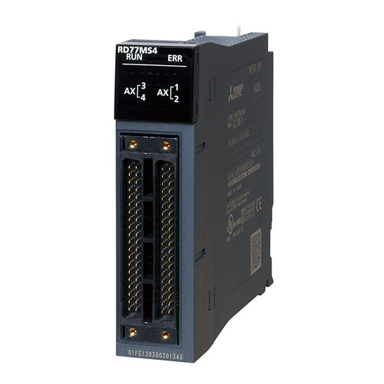
Page 18: Chapter 1 Part Names
PART NAMES This chapter describes the part names of the Simple Motion module. RD77MS2 RD77MS4 RD77MS8 RD77MS16 RD77MS8 RD77MS16 RD77MS2 RD77MS4 AX1-8 AX1-16 Name Description RUN LED For details, refer to the following. Page 17 LED Display Specifications ERR LED... -
Page 19: Led Display Specifications
LED Display Specifications This section lists LED display specifications. : OFF, : ON, ●: Flashing Simple Motion LED display Description module status AX1 RUN Normal operation The axes stopped ERR AX2 The axes on standby AX3 AX4 ... -
Page 20: Chapter 2 Specifications
SPECIFICATIONS This chapter describes the performance specifications of the RD77MS. Performance Specifications This section lists the performance specifications of the RD77MS. Item RD77MS2 RD77MS4 RD77MS8 RD77MS16 Number of controlled axes 2 axes 4 axes 8 axes 16 axes Operation cycle 0.444 ms/0.888 ms/1.777 ms/3.555 ms... - Page 21 Item RD77MS2 RD77MS4 RD77MS8 RD77MS16 Starting time Operation cycle Maximum number 0.7 ms 0.444 ms of axes: 1 axis Maximum number 0.7 ms of axes: 2 axes Maximum number 0.74 ms of axes: 4 axes Operation cycle Maximum number 1.1 ms 0.888 ms...
-
Page 22: Specifications Of Interfaces With External Devices
External input signal ■Specifications of external input signal Item Specifications Signal name Input signal (SIN) Number of input points RD77MS2: 10 points, RD77MS4/RD77MS8/RD77MS16: 20 points Input method Positive common/Negative common shared Common terminal arrangement 4 points/common (Common contact: COM) Isolation method Photocoupler... - Page 23 Manual pulse generator/Incremental synchronous encoder input ■Specifications of manual pulse generator/incremental synchronous encoder Item Specifications Signal input form Phase A/Phase B (Magnification by 4/Magnification by 2/Magnification by 1), PULSE/SIGN Differential-output type Maximum input pulse frequency 1 Mpulses/s (After magnification by 4, up to 4 Mpulses/s) (26LS31 or equivalent) 1 s or more Pulse width...
-
Page 24: External Circuit Design
External Circuit Design Configure up the power supply circuit and main circuit which turn off the power supply after detection alarm occurrence and servo forced stop. When designing the main circuit of the power supply, make sure to use a circuit breaker (MCCB). The outline diagrams for the external device connection interface are shown below. - Page 25 *1 Configure up the power supply circuit which switches off the electromagnetic contactor (MC) after detecting the alarm occurrence on the CPU module. *2 It is also possible to use a full wave rectified power supply as the power supply for the electromagnetic brake. *3 It is also possible to perform the forced stop using a forced stop terminal of the servo amplifier.
- Page 26 Example when using the forced stop of the Simple Motion module (For MR-JE-B) • The hot line forced stop function is enabled at the MR-JE-B factory-set. (Only MR-JE-B) • This function is used to execute deceleration stop for all axes by outputting the hot line forced stop signal to all axes and generating "E7.1"...
- Page 27 *1 Configure up the power supply circuit which switches off the electromagnetic contactor (MC) after detecting the alarm occurrence on the CPU module. *2 It is also possible to use a full wave rectified power supply as the power supply for the electromagnetic brake. *3 It is also possible to perform the forced stop using a forced stop terminal of the servo amplifier.
- Page 28 Example when using the forced stop of the Simple Motion module and MR-J4-B 3-phase 200 to 230 V AC Power supply CPU module Simple Output module R61P RnCPU Motion RY41P MCCB1 module RD77MS R S T INPUT Forced stop 100-240VAC 12/24VDC EMI.COM SSCNET...
- Page 29 *1 Configure up the power supply circuit which switches off the electromagnetic contactor (MC) after detecting the alarm occurrence on the CPU module. It is also possible to use a full wave rectified power supply as the power supply for the electromagnetic brake. *3 Set the axis selection rotary switch of servo amplifier as follows to set the axis No.
- Page 30 Example when using the forced stop of the Simple Motion module and MR-JE-B • The hot line forced stop function is enabled at the MR-JE-B factory-set. (Only MR-JE-B) • This function is used to execute deceleration stop for all axes by outputting the hot line forced stop signal to all axes and generating "E7.1"...
- Page 31 *1 Configure up the power supply circuit which switches off the electromagnetic contactor (MC) after detecting the alarm occurrence on the CPU module. It is also possible to use a full wave rectified power supply as the power supply for the electromagnetic brake. *3 Set the axis selection rotary switch of servo amplifier as follows to set the axis No.
-
Page 32: Chapter 3 Function List
FUNCTION LIST Control Functions The Simple Motion module has several functions. Refer to the following for details on each function. MELSEC iQ-R Simple Motion Module User's Manual (Application) In this manual, the Simple Motion module functions are categorized and explained as follows. Main functions ■Home position return control "Home position return control"... -
Page 33: Main Functions
Main Functions The outline of the main functions for positioning control with the Simple Motion module is described below. Main functions Details Home position Machine home position return control Mechanically establishes the positioning start point using a near-point dog, etc. return control In the data setting method, no axis movement occurs since the current position is set as the home position. - Page 34 Main functions Details Manual JOG operation Outputs a command to servo amplifier while the JOG start signal is ON. control Inching operation Outputs commands corresponding to minute movement amount by manual operation to servo amplifier. (Performs fine adjustment with the JOG start signal.) Manual pulse generator operation Outputs pulses commanded with the manual pulse generator to servo amplifier.
-
Page 35: Sub Functions And Common Functions
Sub Functions and Common Functions Sub functions The outline of the functions that assist positioning control using the Simple Motion module is described below. Sub function Details Functions Home position return retry This function retries the home position return with the upper/lower limit switches during the machine home characteristic to function position return. - Page 36 Sub function Details Other functions Skip function This function stops (decelerates to a stop) the positioning being executed when the skip signal is input, and carries out the next positioning. M code output function This function issues a command for a sub work (clamp or drill stop, tool change, etc.) corresponding to the M code No.
-
Page 37: Common Functions
Common functions The outline of the functions executed as necessary is described below. Common functions Details Parameter initialization function This function returns the setting data stored in the buffer memory/internal memory and flash ROM/internal memory (nonvolatile) of Simple Motion module to the default values. The following two methods can be used. -
Page 38: Combination Of Main Functions And Sub Functions
Combination of Main Functions and Sub Functions With positioning control using the Simple Motion module, the main functions and sub functions can be combined and used as necessary. A list of the main function and sub function combinations is given below. Combination of main functions and operation patterns : Combination possible : Combination limited... - Page 39 Combination of main functions and sub functions : Combination possible : Combination limited : Combination not possible Main functions Functions characteristic to Functions that compensate control machine home position return Home Home Backlash Electronic Near pass position position shift compensation gear function function return retry...
- Page 40 : Always combine : Combination possible : Combination not possible Main functions Functions that limit control Speed limit Torque limit Software Hardware Forced stop function function stroke limit stroke limit function function function Home Machine home position return control position ...
- Page 41 : Combination possible : Combination limited : Combination not possible Main functions Functions that change control details Speed change Override Acceleration/ Torque Target function function deceleration change position time change function change function function Home Machine home position return control position ...
- Page 42 : Combination possible : Combination limited : Combination not possible Main functions Functions Functions related to Other functions related to positioning stop positioning start Pre-reading Step function Stop Skip function M code output start function command function processing deceleration stop function ...
- Page 43 : Combination possible : Combination limited : Combination not possible Main functions Other functions Teaching Command Acceleration/ Deceleration Speed Operation function in-position deceleration start flag control 10 setting for function processing function times incompletion function multiplier of home setting for position degree axis return...
-
Page 44: Chapter 4 Procedures Before Operations
PROCEDURES BEFORE OPERATIONS This chapter describes the procedures before operation. Mounting the module Mount the Simple Motion module to the main base unit or extension base unit. For details, refer to the following. MELSEC iQ-R Module Configuration Manual Wiring Connect the Simple Motion module to external devices. Adding the module Add the RD77MS to the module map of the project using an engineering tool. -
Page 45: Chapter 5 Wiring
WIRING Precautions for Wiring The precautions for wiring the Simple Motion module are shown below. Execute the work following the precautions below. Warning for wiring WARNING • Completely turn off the externally supplied power used in the system before installation or wiring. Not doing so could result in electric shock or damage to the product. - Page 46 CAUTION • Migrating plasticizer is used for vinyl tape. Keep the MR-J3BUS_M, and MR-J3BUS_M-A cables away from vinyl tape because the optical characteristic may be affected. Generally, soft polyvinyl chloride (PVC), polyethylene resin (PE) and fluorine resin contain non-migrating plasticizer and they do not affect the optical characteristic of SSCNET...
- Page 47 Precautions for SSCNET cable wiring SSCNET cable is made from optical fiber. If optical fiber is added a power such as a major shock, lateral pressure, haul, sudden bending or twist, its inside distorts or breaks, and optical transmission will not be available. Especially, as optical fiber for MR-J3BUS_M, MR-J3BUS_M-A is made of synthetic resin, it melts down if being left near the fire or high temperature.
- Page 48 ■Wiring process of SSCNET cable Put the SSCNET cable in the duct or fix the cable at the closest part to the Simple Motion module with bundle material in order to prevent SSCNET cable from putting its own weight on SSCNET connector. Leave the following space for wiring. •...
- Page 49 Example of measure against noise for compliance with the EMC directive Control panel: EC-SCF25-78 module (Nitto Kogyo Corporation) Power supply RD77MS module Manual pulse generator, External input signal cable 24 V DC power supply for EMI, External input device, etc. Servo amplifier SSCNETIII cable AC power...
-
Page 50: External Input Connection Connector
SIN6 SIN1 *1 RD77MS2 does not have the connector of 2A20 to 2A1 and 2B20 to 2B1. *2 Input type from manual pulse generator/incremental synchronous encoder is switched in "[Pr.89] Manual pulse generator/Incremental synchronous encoder input type selection". (Only the value specified against the axis 1 is valid.) •... -
Page 51: List Of Input Signal Details
List of input signal details Signal name Pin No. Signal details Differential- Manual pulse 1A17 (1) Phase A/Phase B output type generator/ (A+) • Input the pulse signal from the manual pulse generator/incremental synchronous encoder A phase and B Incremental phase. - Page 52 This power supply is used for manual pulse generator. It must not be used except for the manual pulse generator power supply. *1 There are no signals of 2A_ and 2B_ at RD77MS2 use. 5 WIRING 5.2 External Input Connection Connector...
-
Page 53: Interface Internal Circuit
Interface internal circuit The outline diagrams of the internal circuits for the external device connection interface (for the Simple Motion module, axis 1) are shown below. Interface between external input signals/forced stop input signals Input or Signal name Pin No. Wiring example Description Output... - Page 54 ■Interface between manual pulse generator/Incremental synchronous encoder (Voltage-output type/open-collector type) Input or Signal name Pin No. Wiring example Output *1, *2 Input Manual pulse generator, 1B19 Internal circuit phase A/PULSE Manual pulse generator, 1B20 phase B/SIGN Manual pulse generator/ Incremental synchronous encoder Power...
- Page 55 ■Manual pulse generator/Incremental synchronous encoder of differential output type When using the external When using the internal power supply (Recommended) power supply Manual pulse generator/ Manual pulse generator/ Incremental synchronous Incremental synchronous RD77MS encoder RD77MS encoder HAH (A+) HAH (A+) HAH (A+) (A+) HAL (A-)
-
Page 56: Chapter 6 Operation Examples
OPERATION EXAMPLES This chapter describes the programming procedure and the basic program of the Simple Motion module. When applying the program examples provided in this manual to an actual system, properly verify the applicability and reliability of the control on the system. - Page 57 System configuration The following figure shows the system configuration used for the program examples in this section. (1) R61P (2) R16CPU RD77MS16 (3) RD77MS16 (X0 to X1F/Y0 to Y1F) AX1-16 (4) RX40C7 (X20 to X3F) (5) RX40C7 (X40 to X5F) X40 to X45 External device X20 to X3F...
- Page 58 ■Parameters The following table lists parameters. Use the default values for the setting items not listed here or the setting items for the axes not described here. Setting item Setting value (Axis 1) Common parameters [Pr.82] Forced stop valid/invalid selection 1: Invalid Basic parameters 1 [Pr.1] Unit setting...
- Page 59 List of labels to be used The following table lists the labels used for the program examples in this section. I/O signals or buffer memory areas of the modules shown in the system configuration are described in the programs using the labels. For details on the global labels, refer to the following.
- Page 60 Device name Setting details Application Label name Data type Class Assign (Device/Label) Internal relay, bABRSTReq VAR_GLOBAL Absolute position restoration command data device bBasicParamSetComp Basic parameter 1 setting complete bDuringJogInchingOperation In-JOG/Inching operation flag bDuringMPGOperation Manual pulse generator operating flag bFastOPRStartReq Fast home position return command bFastOPRStartReq_H Fast home position return command storage...
- Page 61 ■Positioning start No. setting program 6 OPERATION EXAMPLES...
- Page 62 ■Positioning start program ■JOG operation setting program 6 OPERATION EXAMPLES...
- Page 63 ■JOG operation execution program 6 OPERATION EXAMPLES...
-
Page 64: Appendices
RD77MS16 Servo amplifier Manual pulse generator Recommended: MR-HDP01 (Manufactured by Mitsubishi Electric Corporation) Operation has been checked: UFO-M2-0025-2Z1-B00E (Manufactured by Nemicon Corporation) RE45BA2R5C (Manufactured by Tokyo Sokuteikizai Co., Ltd.) SSCNET cable Cables are needed for connecting the Simple Motion module with a servo amplifier, or between servo amplifiers. - Page 65 Nemicon Corporation UFO-M2-0025-2Z1-B00E Tokyo Sokuteikizai Co., Ltd. RE45BA2R5C *1 Contact: http://www.nemicon.co.jp/nemicon/ *2 Contact: http://www.tosoku-inc.co.jp/ External dimension drawing of manual pulse generator MR-HDP01 (Manufactured by Mitsubishi Electric Corporation) [Unit: mm (inch)] 3 × Studs (M4 × 10) ±0.5 (0.14) 27.0 (1.06) PCD72, equi-spaced M3 ×...
- Page 66 Serial absolute synchronous encoder specifications Item Specifications Model name Q171ENC-W8 Ambient temperature -5 to 55 (23 to 131) Resolution 4194304 pulses/rev Transmission method Serial communications (Connected to MR-J4-_B-RJ) Direction of increasing addresses CCW (viewed from end of shaft) Protective construction Dustproof/Waterproof (IP67: Except for the shaft-through portion.) Permitted speed at power ON 3600 r/min...
- Page 67 Serial absolute synchronous encoder cable Generally use the serial absolute synchronous encoder cables available as our products. If the required length is not found in our products, fabricate the cable by a customer side. ■Selection The following table indicates the serial absolute synchronous encoder cables used with the serial absolute synchronous encoder.
- Page 68 ■Q170ENCCBL_M-A • Model explanation Type: Q170ENCCBL_M - A Cable length [m (ft.)] Symbol 2 (6.56) 5 (16.40) 10 (32.81) 20 (65.62) 30 (98.43) 50 (164.04) • Connection diagram When fabricating a cable, use the recommended wire and connector set MR-J3CN2 for encoder cable given above, and make the cable as shown in the following connection diagram.
- Page 69 External dimension drawing of serial absolute synchronous encoder ■Serial absolute synchronous encoder (Q171ENC-W8) [Unit: mm (inch)] 85(3.35) 58.5(2.30) 29(1.14) 30(1.18) 7(0.28) 45° 2(0.08) 14(0.55) 8.72 (0.34) Cross-section diagram AA' 4-5.5 (0.22) 42(1.65) 37.5(1.48) APPENDICES APPENDIX Appendix 1 Component List...
-
Page 70: Appendix 2 Connection With External Devices
Appendix 2 Connection with External Devices Connector Mounted onto an external input connection connector of the Simple Motion module and used for wiring an external device. The "external device connector" includes the following 3 types. Appearance A6CON1 A6CON2 A6CON4 Connector type Type Model Connector... -
Page 71: External Input Signal Cable
External input signal cable The external input signal cable is not prepared as an option. Fabricate the cable on the customer side. Make the cable as shown in the following connection diagram. Solderless terminal (1) Manual pulse generator/incremental Simple Motion module synchronous encoder side (1A_ _, 1B_ _ ) - Page 72 ■Voltage-output/Open-collector type Make the cable within 10 m (32.81 ft.). 1B18 1A18 1B17 1A17 1B20 1A20 1B19 Voltage-output/open-collector type Manual pulse generator/ 1A19 incremental synchronous encoder side 1B15 1B14 1A15 1A14 : Twisted pair cable *1 Ground FG terminal on the used equipment side. Also, connect it to the shell of connector side. APPENDICES APPENDIX Appendix 2 Connection with External Devices...
- Page 73 Forced stop input/ External input signal The following connection diagram shows an example using the assignment below. The assignment can be changed arbitrarily. Input signal External input signal SIN1 SIN2 SIN3 SIN4 STOP SIN5 SIN6 SIN7 SIN8 SIN9 STOP SIN10 Forced stop input side EMI.COM EMI.COM...
- Page 74 External input signal The following connection diagram shows an example using the assignment below. The assignment can be changed arbitrarily. Input signal External input signal SIN11 SIN12 SIN13 SIN14 STOP SIN15 SIN16 SIN17 SIN18 SIN19 STOP SIN20 SIN15(DI3) SIN15(DI3) SIN14(STOP) SIN14(STOP) SIN13(DOG) SIN13(DOG)
- Page 75 • The following table indicates the external input wiring connector cables. Make selection according to your operating conditions. Wire model Core size Number Characteristics of one core Finish OD of cores [mm] Structure [Number Conductor Insulating sheath OD of wires/mm] resistance [/km] d [mm] 17/0.16 1P SRV-SV(2464)-K...
-
Page 76: Appendix 3 External Dimensions
Appendix 3 External Dimensions RD77MS2 [Unit: mm(inch)] RD77MS2 27.8(1.09) 110(4.33) RD77MS4 [Unit: mm(inch)] RD77MS4 27.8(1.09) 110(4.33) APPENDICES APPENDIX Appendix 3 External Dimensions... - Page 77 RD77MS8 [Unit: mm(inch)] RD77MS8 AX1-8 27.8(1.09) 110(4.33) RD77MS16 [Unit: mm(inch)] RD77MS16 AX1-16 27.8(1.09) 110(4.33) APPENDICES APPENDIX Appendix 3 External Dimensions...
-
Page 78: Index
INDEX 0 to 9 ... . 31 ....33 3-axis helical interpolation control Hardware stroke limit function . - Page 79 ....35 Optional data monitor function ..... . . 33 Override function .
-
Page 80: Revisions
Japanese manual number: IB-0300244-B This manual confers no industrial property rights of any other kind, nor does it confer any patent licenses. Mitsubishi Electric Corporation cannot be held responsible for any problems involving industrial property rights which may occur as a result of using the contents noted in this manual. -
Page 81: Warranty
WARRANTY Please confirm the following product warranty details before using this product. 1. Gratis Warranty Term and Gratis Warranty Range If any faults or defects (hereinafter "Failure") found to be the responsibility of Mitsubishi occurs during use of the product within the gratis warranty term, the product shall be repaired at no cost via the sales representative or Mitsubishi Service Company. - Page 82 TRADEMARKS Microsoft, Windows, Windows Vista, Windows NT, Windows XP, Windows Server, Visio, Excel, PowerPoint, Visual Basic, Visual C++, and Access are either registered trademarks or trademarks of Microsoft Corporation in the United States, Japan, and other countries. Intel, Pentium, and Celeron are either registered trademarks or trademarks of Intel Corporation in the United States and other countries.
- Page 84 IB(NA)-0300245-B(1502)MEE MODEL: RD77-U-S-E MODEL CODE: 1XB012 HEAD OFFICE : TOKYO BUILDING, 2-7-3 MARUNOUCHI, CHIYODA-KU, TOKYO 100-8310, JAPAN NAGOYA WORKS : 1-14 , YADA-MINAMI 5-CHOME , HIGASHI-KU, NAGOYA , JAPAN When exported from Japan, this manual does not require application to the Ministry of Economy, Trade and Industry for service transaction permission.
Need help?
Do you have a question about the RD77MS2 and is the answer not in the manual?
Questions and answers