
Related Manuals for Tektronix AWG710


Summary of Contents for Tektronix AWG710
- Page 1 User Manual AWG710 & AWG710B 4 GS/s / 4.2 GS/s Arbitrary Waveform Generator 071-1413-01 This document supports firmware version 4.00 and above. www.tektronix.com...
- Page 2 Copyright © Tektronix Japan, Ltd. All rights reserved. Copyright © Tektronix, Inc. All rights reserved. Tektronix products are covered by U.S. and foreign patents, issued and pending. Information in this publication supercedes that in all previously published material. Specifications and price change privileges reserved.
- Page 3 Tektronix, with shipping charges prepaid. Tektronix shall pay for the return of the product to Customer if the shipment is to a location within the country in which the Tektronix service center is located. Customer shall be responsible for paying all shipping charges, duties, taxes, and any other charges for products returned to any other locations.
-
Page 5: Table Of Contents
Contacting Tektronix ........ - Page 6 About Undo ............3-104 AWG710&AWG710B Arbitrary Waveform Generator User Manual...
- Page 7 Diff( ) ............3-194 AWG710&AWG710B Arbitrary Waveform Generator User Manual...
- Page 8 Operation Flow ........... . . 3-257 AWG710&AWG710B Arbitrary Waveform Generator User Manual...
- Page 9 Synchronous Operation Tests......... . . B-52 Performance Verification (AWG710) ........B-55 Conventions .
- Page 10 Index ............Index-1 AWG710&AWG710B Arbitrary Waveform Generator User Manual...
- Page 11 2-37 Figure 2-27: AWG710 block diagram ........
- Page 12 Figure 2-49: Example of sequence (MAINSEQ.seq) ..... . . 2-80 Figure 3-1: Overview of AWG710&AWG710B Arbitrary Waveform Generator process flow ........3-1 Figure 3-2: Setup main screen (except option 02) .
- Page 13 Figure A-4: Sequence 2 ..........A-12 AWG710&AWG710B Arbitrary Waveform Generator User Manual...
- Page 14 Figure B-39: Cont mode initial test hookup ......B-66 Figure B-40: Triggered mode initial test hookup ......B-68 AWG710&AWG710B Arbitrary Waveform Generator User Manual...
- Page 15 Figure F-3: Conversion image example ....... . . AWG710&AWG710B Arbitrary Waveform Generator User Manual...
- Page 16 List of Tables Table 1-1: AWG710&AWG710B waveform editors ..... . . 1-2 Table 1-2: Power cord options ......... 1-5 Table 1-3: Language options .
- Page 17 Table A-12: VCO output Cycle to Cycle Jitter ......A-7 xiii AWG710&AWG710B Arbitrary Waveform Generator User Manual...
- Page 18 Table D-5: Squared sine pulse ......... AWG710&AWG710B Arbitrary Waveform Generator User Manual...
- Page 19 Table D-22: Isolated pulse for network application ..... . D-12 Table D-23: Isolated pulse for network application ..... . D-12 AWG710&AWG710B Arbitrary Waveform Generator User Manual...
- Page 20 List of Tables AWG710&AWG710B Arbitrary Waveform Generator User Manual...
- Page 21 Do Not Operate in an Explosive Atmosphere. Keep Product Surfaces Clean and Dry. Provide Proper Ventilation. Refer to the manual’s installation instructions for details on installing the product so it has proper ventilation. AWG710&AWG710B Arbitrary Waveform Generator User Manual xvii...
- Page 22 CAUTION indicates a hazard to property including the product. Symbols on the Product. The following symbols may appear on the product: WARNING Protective Ground CAUTION Double High Voltage (Earth) Terminal Refer to Manual Insulated xviii AWG710&AWG710B Arbitrary Waveform Generator User Manual...
- Page 23 Preface This manual provides user information for the AWG710&AWG710B Arbitrary Waveform Generator. Manual Structure The AWG710&AWG710B Arbitrary Waveform Generator User Manual contains the following sections: The Getting Started section covers initial instrument inspection, available options and accessories, instrument installation procedures, and power on and off procedures.
- Page 24 Turn the indicated front–panel control knob (usually the general purpose knob) pop–up Make selections or change values in the indicated pop–up menu dialog Make selections or change values in the indicated dialog box screen Make selections or change values on the indicated instrument screen AWG710&AWG710B Arbitrary Waveform Generator User Manual...
-
Page 25: Related Manuals
Preface Related Manuals Following are additional manuals that are available for the AWG710&AWG710B Arbitrary Waveform Generator: The AWG710&AWG710B Arbitrary Waveform Generator Programmer Manual provides complete information on programming and remote control of the instrument through the GPIB/Ethernet interfaces. This manual is a standard accessory. - Page 26 Preface xxii AWG710&AWG710B Arbitrary Waveform Generator User Manual...
- Page 27 Getting Started...
-
Page 29: Getting Started
The AWG710&AWG710B Arbitrary Waveform Generator allows you to create sine, triangle, square, ramp, and complex waves, as well as direct current and noises signals. It allows you to set waveform attributes, such as frequency, amplitude, and offset. -
Page 30: Table 1-1: Awg710&Awg710B Waveform Editors
Getting Started 32.4 M–word waveform memory (62.8 M optional):AWG710B 16.2 M–word waveform memory (32.4 M optional): AWG710 Two arbitrary marker outputs Five waveform editors (see Table 1-1) Table 1-1: AWG710&AWG710B waveform editors Editor Description Waveform Creates analog waveform data in graphic or tabular form. - Page 31 Getting Started An adjustment of focused color. Refer to Focused Color on page 3-158 for information. This setup procedure is also described in Tutorial 1: Instrument Setup on page 2-51. AWG710&AWG710B Arbitrary Waveform Generator User Manual...
-
Page 32: Incoming Inspection
Inspect the AWG710&AWG710B Arbitrary Waveform Generator carton for external damage. If the carton is damaged, notify the carrier. Remove the AWG710&AWG710B Arbitrary Waveform Generator from its carton and check that the instrument has not been damaged in transit. Verify that the carton contains the basic instruments and its standard accessories. -
Page 33: Table 1-2: Power Cord Options
Getting Started Power Cord Options Arbitrary Table 1-2 lists the power cords available with the AWG710&AWG710B Waveform Generator Table 1-2: Power cord options Option Description Tektronix part number Standard US Power Cord, 115 V 161–0104–00 Europe, 220 V 161–0104–06 United Kingdom, 240 V 161–0104–07... -
Page 34: Table 1-4: Standard Accessories
Getting Started Accessories Standard Accessories The AWG710&AWG710B Arbitrary Waveform Generator includes the standard accessories listed in Table 1-4: Table 1-4: Standard accessories Accessory Part number User Manual See Table 1-3 for part Programmer Manual number Sample waveform floppy disk, 3.5 inch for AWG710B 063–3740–xx... - Page 35 BNC low pass filter, 200 MHz 015–0658–00 BNC low pass filter, 100 MHz 015–0657–00 SMA delay cable, 1 ns, Male–Male 015–0562–00 AC Current Probe CT-1 AC Current Probe CT-2 AC Current Probe CT-3 Cart K475 AWG710&AWG710B Arbitrary Waveform Generator User Manual...
-
Page 36: Options
Option 1R (Rack Mounting) AWG710&AWG710B Arbitrary Waveform Generator comes configured for installation in a 19–inch wide instrument rack. For later field conversions, order Rack Mount Kit (020-2556-00) or contact your local Tektronix sales office or representative. Option D1 (Test Result... - Page 37 The security and handling of data are improved by using a removable hard disk. A calibration data test result report will be provided with the Option D1,TDAT (Test AWG710&AWG710B Arbitrary Waveform Generator when this option is Result Report) specified. D1is English and TDAT is Japanese. AWG710&AWG710B Arbitrary Waveform Generator User Manual...
-
Page 38: Installation
To prevent damage to the instrument, do not power on the instrument at temperatures outside the specified temperature range. The AWG710&AWG710B Arbitrary Waveform Generator operates correctly in ambient temperatures from +10° C to +40° C and relative humidity from 20% to 80%. -
Page 39: Table 1-6: Fuse And Fuse Cap Part Numbers
NOTE. standards. This fuse is used in equipment sold in the European market. Check Voltage Settings Check that you have the proper electrical connections. The AWG710&AWG710B Arbitrary Waveform Generator operates within the following power supply voltage and frequency ranges: Line voltage range... -
Page 40: Table 1-7: Power Cord Identification
Power is now applied to the instrument standby circuitry. Once the instrument is installed, leave the PRINCIPAL POWER SWITCH on and use the ON/STBY switch, located on the front–panel, to turn the instrument on and off. 1-12 AWG710&AWG710B Arbitrary Waveform Generator User Manual... -
Page 41: Figure 1-1: Rear Panel Power Switch, Fuse Holder, And Power Connector
Getting Started PRINCIPAL POWER SWITCH Fuse Power connector Figure 1-1: Rear panel power switch, fuse holder, and power connector AWG710&AWG710B Arbitrary Waveform Generator User Manual 1-13... -
Page 42: Figure 1-2: Location Of The On/Stby Switch
In addition, AWG cannot start up when floppy disk other than a system disk is inserted in the floppy disk drive. Please power on after ejecting a disk. ON/STBY switch Figure 1-2: Location of the ON/STBY switch 1-14 AWG710&AWG710B Arbitrary Waveform Generator User Manual... - Page 43 To exit the diagnosis mode, push any button. The system goes to the SETUP menu screen. Contact your local Tektronix Field Office or representative if the instrument NOTE.
-
Page 44: Repackaging For Shipment
3 inches greater than the instrument dimensions and having a carton test strength of at least 125 kg (275 lb.). 2. If the instrument is being shipped to a Tektronix Service Center for repair or calibration, attach a tag to the instrument showing the following information: The owner of the instrument (with address). - Page 45 Operating Basics...
-
Page 47: Operating Basics
Doing so can cause data corruption on the floppy disk and cause the instrument to hang up. If this happens, turn power off then back on again. To prevent damage to the instrument, do not apply any external voltage to the output connector or marker connector. AWG710&AWG710B Arbitrary Waveform Generator User Manual... -
Page 48: Figure 2-1: Front Panel Controls (Awg710)
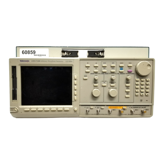
The LED indicator is on when the disk drive is in operation. To prevent damage to the instrument, do not apply the voltage to OUTPUT or MARKER connectors. Figure 2-1: Front panel controls (AWG710) AWG710&AWG710B Arbitrary Waveform Generator User Manual... -
Page 49: Figure 2-2: Front Panel Controls (Awg710B)
The LED indicator is on when the disk drive is in operation. To prevent damage to the instrument, do not apply the voltage to OUTPUT or MARKER connectors. Figure 2-2: Front panel controls (AWG710B) AWG710&AWG710B Arbitrary Waveform Generator User Manual... -
Page 50: Figure 2-3: Front Panel Keypad Area
ENTER to confirm the settings. INF button Sets the Repeat Count to Inf. in the sequence editor. This button can be used only for this purpose. Figure 2-3: Front panel keypad area AWG710&AWG710B Arbitrary Waveform Generator User Manual... -
Page 51: Figure 2-4: Front Panel Trigger And Output Controls
The OFFSET knob, adjusts the vertical offset. The OFFSET knob adjusts the horizontal position. The LEVEL/SCALE knob adjusts the amplitude. The SAMPLE RATE/SCALE knob adjusts the clock frequency. Figure 2-4: Front panel trigger and output controls AWG710&AWG710B Arbitrary Waveform Generator User Manual... -
Page 52: Figure 2-5: Rear Panel Signal And Power Connectors (Awg710)
KEYBOARD connector Power connector connector Connect to a standard PC 101-key keyboard. Connect the provided power cable to this Connect to an external monitor. connector. Figure 2-5: Rear panel signal and power connectors (AWG710) AWG710&AWG710B Arbitrary Waveform Generator User Manual... -
Page 53: Figure 2-6: Rear Panel Signal And Power Connectors (Awg710B)
External clock signal input. An acceptable external clock signal is 0.4 to 2.0 V input voltage, 50±5 % duty cycle, and 125 MHz to 4.2 GHz frequency range. Figure 2-6: Rear panel signal and power connectors (AWG710B) AWG710&AWG710B Arbitrary Waveform Generator User Manual... -
Page 54: Figure 2-7: Menu Buttons, Bezel Menu Buttons, And The Clear Menu Button
Menu System The AWG710&AWG710B Arbitrary Waveform Generator uses menus to make selections. There are four menu buttons, labeled EDIT, SETUP, APPL, and UTILITY, as shown in Figure 2-7. Pushing a menu button displays the corresponding screen and menu buttons. -
Page 55: Figure 2-8: Bottom And Side Menus
Figure 2-8: Bottom and side menus You use a side menu button to display a side submenu, set a parameter, perform a task, or cancel an operation. Table 2-1 describes the side menu button types. AWG710&AWG710B Arbitrary Waveform Generator User Manual... -
Page 56: Figure 2-9: Pop-Up Menu Example
Use the general purpose knob or the front–panel arrow buttons to move up or down in the list. Push the OK side button or the ENTER front–panel button to confirm the selected item. Figure 2-9: Pop–up menu example 2-10 AWG710&AWG710B Arbitrary Waveform Generator User Manual... -
Page 57: Figure 2-10: Dialog Box Example
Refer to Numeric Input on page 2-12 and Text Input on page 2-14 for more information on selecting and entering values in menus and dialog boxes. Refer to Menu Structures on page 3-3 for information on the menu system. AWG710&AWG710B Arbitrary Waveform Generator User Manual 2-11... -
Page 58: Figure 2-11: Knob Icon Displayed In Status Display Area
Values in pop–up menus are not effective until you push the OK side button or the ENTER front–panel button. The Numeric Keypad Figure 2-12 shows the numeric keypad, with descriptions of the button operations. 2-12 AWG710&AWG710B Arbitrary Waveform Generator User Manual... -
Page 59: Figure 2-12: Keypad Buttons
When you press the 5, 0 and ENTER buttons in this order, the Clock will be set to 50.0 MS/s. To set the Clock to 500 kS/s, press 0, ., 5 and ENTER buttons, or 5, 0, 0, SHIFT, and 8 (k) buttons in this order. AWG710&AWG710B Arbitrary Waveform Generator User Manual 2-13... -
Page 60: Figure 2-13: Three Type Of Input Text Dialog Boxes
To select text from a file name list, use the y and b arrow buttons to move the knob icon to the file name list. Table 2-2 describes all the controls you can use for entering and editing text. 2-14 AWG710&AWG710B Arbitrary Waveform Generator User Manual... -
Page 61: Figure 2-14: Shortcut Controls
Figure 2-14 shows the shortcut buttons and knobs that control specific instrument setup parameters. Using the shortcut controls lets you adjust the output setup parameters even while you are displaying another menu. Table 2-3 describes the shortcut controls. Figure 2-14: Shortcut controls AWG710&AWG710B Arbitrary Waveform Generator User Manual 2-15... -
Page 62: Table 2-3: Shortcut Controls
Displays the Trigger side menu. This is the same as selecting SETUP (front)!Trigger (bottom). Adjusts the trigger level setting. This is the same as selecting SETUP (front)!Trigger (bottom)!Level (side), and then turning the general purpose knob. 2-16 AWG710&AWG710B Arbitrary Waveform Generator User Manual... -
Page 63: Table 2-4: Awg710&Awg710B Arbitrary Waveform Generator File Types
File Type Extensions The AWG710&AWG710B Arbitrary Waveform Generator uses numerous file formats to hold different types of data. These file types are listed in Table 2-4. Note that the instrument checks the file format and processes the file based on its content, regardless of the file extension. -
Page 64: Table 2-5: Drive And Directory Menus
Operating Basics Locating Files There are three locations for storing waveform data on the AWG710&AWG710B Arbitrary Waveform Generator. Data can be stored on the instrument hard disk drive, the instrument floppy disk drive, or a remote storage device accessible through the Ethernet interface. If the file you want to load is not on the current drive, use the EDIT menu main screen Drive and Directory bottom menu buttons to open side menus that let you change the current drive location. - Page 65 The instrument displays the file list. 2. Select the file to rename. 3. Push File (bottom)!Rename (side). 4. Enter the new name for the file in the file name field. 5. Push OK (side). The file is renamed. AWG710&AWG710B Arbitrary Waveform Generator User Manual 2-19...
- Page 66 The xxxx is the Read/Write or Read Only attribute of the selected file. Pushing this side button immediately changes the file attribute. The file with a read only attribute is marked by , and the directory by . See Figure 2-15. 2-20 AWG710&AWG710B Arbitrary Waveform Generator User Manual...
-
Page 67: Figure 2-15: Files And Directories With Read Only Attribute
Drive... side menu button. Enter the file name, then push the OK side button or the ENTER front–panel button to close the dialog box and save the file. Figure 2-16: Input Filename dialog box AWG710&AWG710B Arbitrary Waveform Generator User Manual 2-21... -
Page 68: Table 2-6: Waveform Record Length Adjustment Messages
Archive. When you select Directory in the file list, you can make archives for all the files in the directory and subdirectory. 1. Push EDIT (front). The instrument displays the file list. 2. Select the file to make archive files. 2-22 AWG710&AWG710B Arbitrary Waveform Generator User Manual... - Page 69 3. Push Directory (bottom)!Extract (side). The instrument extracts the archived files and directories to current directory. Remote computer archive operation. AWG710&AWG710B Arbitrary Waveform Generator uses .tar format files. Use the tar command when you archive with a remote computer environment. If you are PC user, use tar format archive tool.
-
Page 70: Figure 2-17: File List Window Examples In Which Quick View Is Available
Select a file from the file list window using the general purpose knob. Press the SHIFT and ENTER front–panel buttons simultaneously. The view window displaying the waveform or pattern appears as shown in Figure 2-18. 2-24 AWG710&AWG710B Arbitrary Waveform Generator User Manual... -
Page 71: Figure 2-18: Viewing A File By Quick View Function
Push the OK side menu button to close the view window. You cannot view files other than waveform or pattern in this function. This function is always available when a file list window or file list dialog box is displayed on the screen. AWG710&AWG710B Arbitrary Waveform Generator User Manual 2-25... -
Page 72: Table 2-7: Editors
Refer to the Reference section for more detailed information about each waveform editor. This section also provides an overview of the AWG710&AWG710B Arbitrary Waveform Generator waveform editors. There are five editors that provide the tools for creating simple or complicated waveforms. -
Page 73: Figure 2-19: Main Edit Screen
Net Drive are displayed. Window Lets you open a single window or double window that displays a file list of a specified directory or drive. Refer to page 3-230 for information about double windows. AWG710&AWG710B Arbitrary Waveform Generator User Manual 2-27... -
Page 74: Figure 2-20: Edit Top Level Menu Screen With Edit Side Menu
Edit side menu items as shown in Figure 2-20. Table 2-9 provides an overview of the Edit side menu button functions. Edit selected file Create a new waveform Figure 2-20: Edit top level menu screen with Edit side menu 2-28 AWG710&AWG710B Arbitrary Waveform Generator User Manual... -
Page 75: Figure 2-21: Editor Screen Elements
Status Clock Waveform display area frequency Knob icon file name mode Active Window number cursor position Waveform record length Data edit/display area Side menu Marker display Bottom menu Figure 2-21: Editor screen elements AWG710&AWG710B Arbitrary Waveform Generator User Manual 2-29... -
Page 76: Figure 2-22: Cursors And Edit Area
To move a cursor, turn the general purpose knob, use the left or right arrow keys, or use the keypad or keyboard to enter a position in the cursor position field. The cursor position field is active when the corresponding cursor is active. 2-30 AWG710&AWG710B Arbitrary Waveform Generator User Manual... -
Page 77: Figure 2-23: Multiple Editor Windows
0 point and to move the right cursor to the maximum point. Multiple Editor Windows The AWG710&AWG710B Arbitrary Waveform Generator can open and edit up to three waveform and/or pattern files, in any combination. The waveform data is displayed in separate windows, with each window stacked vertically on the screen. - Page 78 To select the active window, push Window (bottom)!Window1, Window2, or Window3 (side). All editing operations will affect the waveform data in that window until you change to another editor window. 2-32 AWG710&AWG710B Arbitrary Waveform Generator User Manual...
- Page 79 2. If you have made no modifications to the data, the editor is immediately exited. If you have not saved the data after modifications, the message box Save the changes you made? appears. Push Yes, No, or Cancel side button. Refer to page 2-21 for saving files. AWG710&AWG710B Arbitrary Waveform Generator User Manual 2-33...
-
Page 80: Figure 2-24: Main Setup Screen (Except Option02)
Table 2-11 lists the bottom menu functions. Clock frequency Run mode Instrument status Waveform parameter icons Side menu area Number of points for loaded waveform Bottom menu Figure 2-24: Main Setup screen (except option02) 2-34 AWG710&AWG710B Arbitrary Waveform Generator User Manual... -
Page 81: Table 2-10: Setup Screen Parameter Icons
Displays the Save/Restore side menu to save and restore setup output parameters. Extended Operation Displays the Extended Operation side menu to change the operation mode such as FG mode, Waveform Mixing mode and Synchronous Operation (AWG710B only) mode. AWG710&AWG710B Arbitrary Waveform Generator User Manual 2-35... -
Page 82: Figure 2-25: Select File Dialog On The Load Menu
So, you can edit a waveform, pattern, sequence or equation/text while outputting an another waveform or sequence. However, when you push SETUP (front–panel)!Waveform/Sequence (bottom)!Edit (side) to copy the waveform in the waveform memory to the edit 2-36 AWG710&AWG710B Arbitrary Waveform Generator User Manual... -
Page 83: Figure 2-26: Viewing A File In The Setup Screen
Even though you change the waveform with the editor and update the waveform memory, the View function still displays the waveform before the update unless you save the file. AWG710&AWG710B Arbitrary Waveform Generator User Manual 2-37... -
Page 84: Table 2-12: Setup Output Parameter Operations
Displays a side menu to set Marker 1 and Marker 2 signal high and low values. The marker signal voltage range is -2.0 V to 2.45 V (-1.1 V to 3.0 V :AWG710) and maximum amplitude is into 50 Ω ( 2.5 V into 50 Ω... - Page 85 Run mode. You can turn either or both channel outputs and marker outputs on or off while the instrument is running by pushing the CH 1 OUT or CH 1 OUT or ALL MARKER OUTPUT AWG710&AWG710B Arbitrary Waveform Generator User Manual 2-39...
- Page 86 To save you from doing a manual setup procedure each time you load a waveform, the AWG710&AWG710B Arbitrary Waveform Generator lets you save setup parameters into a setup file. You can then restore the saved settings for use with waveforms.
-
Page 87: Table 2-13: Run Modes
2 bits per channel for markers, thus a total length of 32.4 M /64.8 M (option 01) (16.2 M /32.4 M (option 01) :AWG710) points. You can set any value from 960 points to 32.4 M/64.8 M (option 01) (16.2 M /32.4 M (option 01) :AWG710) points for the length of waveform data. -
Page 88: Table 2-14: Extended Operation
A control command such as trigger, event or jump from remote device. (Except the Synchronous operation mode) Extended operation. Selecting a Extended operation from the Extended Operation menu causes one of the following to operate the AWG710&AWG710B Arbitrary Waveform Generator: Table 2-14: Extended operation... -
Page 89: Figure 2-27: Awg710 Block Diagram
Memory Register Circuit DAC ASIC CLOCK Frequency Control Clock Output Reference Oscillator Loop Phase Filter Comparator (Hi/Lo band) EXT REF CLOCK (10 MHz) 1/2048 Divider CLOCK (10 MHz) Figure 2-27: AWG710 block diagram AWG710&AWG710B Arbitrary Waveform Generator User Manual 2-43... -
Page 90: Figure 2-28: Awg710B Block Diagram
Operating Basics Trigger Control Event Control Analog Waveform Shift Memory Output Memory Register Address Control Circuit Frequency Control Clock Output Reference Oscillator Phase Loop Comparator Filter 1/2048 Divider Figure 2-28: AWG710B block diagram 2-44 AWG710&AWG710B Arbitrary Waveform Generator User Manual... -
Page 91: Figure 2-29: Relationship Between Memory Address Control And
Memory Repeat Repeat Counter Count End of Waveform Clock Figure 2-29: Relationship between memory address control and waveform memory Figure 2-29 shows the relationship between the memory address control and the waveform memory. AWG710&AWG710B Arbitrary Waveform Generator User Manual 2-45... -
Page 92: Signal Edit Process
The waveform file format includes 8–bits of resolution for the DAC output and 2–bits for the digital marker output. The pattern file format includes 10–bits for digital output (The AWG710&AWG710B supports 2 digital marker outputs). The full–scale resolution of the 8–bit DAC is represented by -1.0 to +1.0. -
Page 93: Table 2-15: Editors
Operating Basics Waveform Edit To enable editing, the AWG710&AWG710B Arbitrary Waveform Generator provides you with Waveform, Pattern, Sequence, Equation, and Text Editors. See Table 2-15 for the explanations of those editors. Table 2-15: Editors Editors Descriptions Waveform Editor The Waveform Editor lets you create or edit a waveform that is being displayed on the screen. - Page 94 Operating Basics 2-48 AWG710&AWG710B Arbitrary Waveform Generator User Manual...
-
Page 95: Tutorials
Creating and executing sequences These tutorials do not cover all the features and functions of the NOTE. AWG710&AWG710B Arbitrary Waveform Generator. They are intended only to introduce the basic instrument functions. By connecting an oscilloscope to the AWG710&AWG710B Arbitrary Waveform Generator and observing the waveforms output, you will understand how the AWG710&AWG710B Arbitrary Waveform Generator works. -
Page 96: Figure 2-30: Cable Connection Between Awg710&Awg710B Arbitrary Waveform Generator And Digital Storage Oscilloscope
50Ω SMA Terminator (Female)-BNC (Male) adapter 50Ω SMA coaxial cable Figure 2-30: Cable connection between AWG710&AWG710B Arbitrary Waveform Generator and digital storage oscilloscope Before beginning the tutorials, confirm that the instrument is installed correctly. Refer to Installation on page 1-9. -
Page 97: Figure 2-32: System Utility Screen
2. Press the System bottom button (lower most–left button) on the bezel. The instrument displays the system utility screen as shown in Figure 2-32. System is currently selected Figure 2-32: System utility screen AWG710&AWG710B Arbitrary Waveform Generator User Manual 2-51... - Page 98 Do the following to turn on the instrument display: 1. Press the ON/STBY button to power on. 2. Press the CLEAR MENU button on the front–panel twice. You have completed the Instrument Setup tutorial. 2-52 AWG710&AWG710B Arbitrary Waveform Generator User Manual...
-
Page 99: Tutorial 2: Loading And Outputting A Sample Waveform
Tutorial 2: Loading and Outputting a Sample Waveform This tutorial shows you how to load and output a waveform from the sample waveform floppy disk provided with the AWG710&AWG710B Arbitrary Waveform Generator. In this tutorial you will learn the following:... -
Page 100: Figure 2-33: The Select File List
This operation loads the selected waveform file into the instrument waveform memory. Confirm that 8000 is displayed in the Points: display field at the lower left of the screen and that LIN_SWP.WFM is displayed in the WFM File: display field. 2-54 AWG710&AWG710B Arbitrary Waveform Generator User Manual... -
Page 101: Figure 2-34: Viewing A Waveform Loaded Into Memory
3. If you connected an oscilloscope to the Waveform Generator, observe that the waveform on the oscilloscope is the same as that shown in Figure 2-34. You have completed the Loading and Outputting a Sample Waveform tutorial. AWG710&AWG710B Arbitrary Waveform Generator User Manual 2-55... -
Page 102: Tutorial 3: Creating And Editing Standard Function Waveforms
1. Push the EDIT button on the front–panel. 2. Push the Edit bottom menu button. 3. Push the New Waveform side menu button. The instrument displays the waveform editors initial screen as shown in Figure 2-35. 2-56 AWG710&AWG710B Arbitrary Waveform Generator User Manual... -
Page 103: Figure 2-35: Waveform Editor Initial Screen
2. Select Standard Waveform... from the pop–up menu by using the general purpose knob. By default, Standard Waveform... is selected. 3. Push the OK side button. The instrument displays the standard function dialog box as shown in Figure 2-36. AWG710&AWG710B Arbitrary Waveform Generator User Manual 2-57... -
Page 104: Figure 2-36: The Standard Function Dialog Box
8. Push the Enter button to enter the value in the field. 9. Push the OK side button. You have created a five–cycle sine wave with a peak–to–peak range of 2.0 digital to analog converter (DAC) units, as shown in Figure 2-37. 2-58 AWG710&AWG710B Arbitrary Waveform Generator User Manual... -
Page 105: Figure 2-37: Standard Sine Wave Function Created In The Waveform Editor
4. Turn the general purpose knob to highlight the Sine item in the Type field. Note that Sine is the default type menu selection. 5. Select Operation in the pop–up menu using the b button. AWG710&AWG710B Arbitrary Waveform Generator User Manual 2-59... -
Page 106: Figure 2-38: Waveform Created With The Multiply Operation
1. Push the File bottom button. The File pop–up menu appears. 2. Select Save from the pop–up menu using the general purpose knob. 2-60 AWG710&AWG710B Arbitrary Waveform Generator User Manual... -
Page 107: Figure 2-39: File Name Input Dialog Box
8. Push the 4 and 5 buttons on the front–panel keypad. Now, ABC45.wfm is displayed in the text field. 9. Push the OK side button. The waveform in the editor is now saved in the file ABC45.wfm. AWG710&AWG710B Arbitrary Waveform Generator User Manual 2-61... - Page 108 4. Push the CH 1 button near the CH 1 output connector on the front panel. If you connected an oscilloscope to the AWG710&AWG710B Arbitrary Waveform Generator, observe that the waveform on the oscilloscope is the same as the one you viewed in Figure 2-38.
-
Page 109: Tutorial 4: Editing A Waveform Using Quick Editor
The Waveform Editor screen appears, as shown in Figure 2-40. 2. Push the front–panel QUICK EDIT button. When you enter into the Quick Editor, the bottom menu buttons are disabled and the Quick Editor side menu is displayed. AWG710&AWG710B Arbitrary Waveform Generator User Manual 2-63... -
Page 110: Figure 2-40: Waveform In The Waveform Editor
The L field is highlighted. The left cursor is a solid line. The right cursor is a dashed line. If the left cursor is not active, push the TOGGLE button on the front panel. 2-64 AWG710&AWG710B Arbitrary Waveform Generator User Manual... -
Page 111: Figure 2-41: Waveform Edit In Quick Editor
Do the following to change the amplitude within the region specified by the area cursor: Turn the LEVEL/SCALE knob clockwise to change the waveform amplitude to 0.5 V. The waveform should look like the one shown in Figure 2-41. Figure 2-41: Waveform edit in quick editor AWG710&AWG710B Arbitrary Waveform Generator User Manual 2-65... - Page 112 Cancel, No, and Yes menu items. 2. Push the Yes side button to save the changes. If you have connected an oscilloscope to the AWG710&AWG710B Arbitrary Waveform Generator, the waveform being displayed on the oscilloscope screen shows the new waveform.
-
Page 113: Tutorial 5: Using The Equation Editor
4. Push the Floppy side button to select the floppy disk drive. The file list for the floppy disk appears. 5. Select the file LOG_SWP.EQU from the file list using the general purpose knob. AWG710&AWG710B Arbitrary Waveform Generator User Manual 2-67... - Page 114 1. Push the Compile side button. When the compile completes, the waveform is saved into the file log_swp.wfm. 2. Push the View side button to view the compiled waveform, as shown in Figure 2-42. 2-68 AWG710&AWG710B Arbitrary Waveform Generator User Manual...
-
Page 115: Figure 2-42: Viewer Displaying Compiled Waveform
3. Push the OK side button to close the viewer screen. 4. Push the Close side button twice to exit the equation editor. You have completed the Using the Equation Editor tutorial. Figure 2-42: Viewer displaying compiled waveform AWG710&AWG710B Arbitrary Waveform Generator User Manual 2-69... -
Page 116: Tutorial 6: Creating And Running Waveform Sequences
The instrument is reset to the factory default setting. 4. Push EDIT button on the front panel. The screen lists the files in the current storage media. Push the EDIT button again to display a list of the files. NOTE. 2-70 AWG710&AWG710B Arbitrary Waveform Generator User Manual... -
Page 117: Table 2-16: Waveforms To Be Used In Sample Sequences
You may use this window function in the waveform editor for creating the above waveforms. Do the following to select a window: 1. Push the Window bottom button. 2. Push the Window 1, Window 2 or Window 3 side button to activate that window. AWG710&AWG710B Arbitrary Waveform Generator User Manual 2-71... -
Page 118: Figure 2-43: Waveforms Created At The Same Time In Three Windows
Figure 2-43: Waveforms created at the same time in three windows Open the Sequence Editor Do the following steps to open the sequence editor and create the sequences: 1. Push the EDIT button on the front panel. 2-72 AWG710&AWG710B Arbitrary Waveform Generator User Manual... -
Page 119: Figure 2-44: Initial Sequence Table
3. Line 3: outputs the triangle waveform 60,000 times and then goes to the next line (4). 4. Line 4: output the sine waveform 30,000 times and then quits the subsequence and returns to the main sequence. AWG710&AWG710B Arbitrary Waveform Generator User Manual 2-73... -
Page 120: Table 2-17: Sequence Table Contents In Subseq.seq
10. Push the 4, 0, 0, 0, 0, and ENTER buttons in this order. The repeat count 40000 is set in the Repeat Count column. 11. Push the b button once to move the highlighted cursor to the next line. 2-74 AWG710&AWG710B Arbitrary Waveform Generator User Manual... -
Page 121: Figure 2-45: Example Of Sequence (Subseq.seq)
12. Repeat steps 10 and 11 to enter the repeat count for lines 2 through 4 as specified in Table 2-17. You have finished editing the sequence table. The table should look like Figure 2-45. Figure 2-45: Example of sequence (SUBSEQ.seq) AWG710&AWG710B Arbitrary Waveform Generator User Manual 2-75... -
Page 122: Table 2-18: Sequence Table Contents In Mainseq.seq
Refer to steps 1 through 12 beginning on page 2-73 of this tutorial if you need help. To set Inf. in the Repeat Count of line 2, push the Infinity (SHIFT + side button once. 3. Repeatedly push the y button to go back to the Line 1. 2-76 AWG710&AWG710B Arbitrary Waveform Generator User Manual... -
Page 123: Figure 2-46: Screen For Setting Jump Mode
8. Push the Jump Mode bottom button. The screen as shown in Figure 2-46 appears. AWG710 AWG710B Figure 2-46: Screen for setting jump mode 1. Push the Logic side button to set the jump mode to Logic Jump. AWG710&AWG710B Arbitrary Waveform Generator User Manual 2-77... -
Page 124: Figure 2-47: Screen For Setting Event Jump
' buttons. 9. Push the a button once to move the highlighted cursor to the Goto <N> column. 10. Push the Data Entry bottom button to go back to the sequence table screen. 2-78 AWG710&AWG710B Arbitrary Waveform Generator User Manual... -
Page 125: Figure 2-48: Setup Of Goto
Enter the number (1 to 8000) by using the general purpose knob or the numeric keypad. This completes the main sequence table editing. The main sequence table should look like Figure 2-49. AWG710&AWG710B Arbitrary Waveform Generator User Manual 2-79... -
Page 126: Figure 2-49: Example Of Sequence (Mainseq.seq)
Enhanced mode. Do the following steps to set the run mode to enhanced: 1. Push the SETUP button on the front–panel to display the SETUP screen. 2. Push the Run Mode bottom button. 3. Push the Enhanced side button. 2-80 AWG710&AWG710B Arbitrary Waveform Generator User Manual... - Page 127 2. Push the CH 1 OUT button near the CH1 connector. The CH1 LED is on. When the subsequence SUBSEQ.seq is recalled, the AWG710&AWG710B Arbitrary Waveform Generator waits for a trigger event. The message Waiting is displayed in the current run status area when the instrument is waiting for a trigger.
- Page 128 FORCE EVENT button. You have completed the Creating and Running Waveform Sequences tutorial. Refer to the Reference section beginning on page 3-1 for detailed information on all instrument functions. 2-82 AWG710&AWG710B Arbitrary Waveform Generator User Manual...
- Page 129 Reference...
-
Page 131: Figure 3-1: Overview Of Awg710&Awg710B Arbitrary Waveform
You can also save the instrument setup information to a file. You can also import waveform and pattern data from an oscilloscope, data generator, or AWG2000-Series instrument. Figure 3-1: Overview of AWG710&AWG710B Arbitrary Waveform Generator process flow AWG710&AWG710B Arbitrary Waveform Generator User Manual... -
Page 132: Table 3-1: Awg710&Awg710B Arbitrary Waveform Generator Main Menus
Reference Menus Table 3-1 lists the four main menus in the AWG710&AWG710B Arbitrary Waveform Generator. Additional menu information can be found in the Reference section of this manual beginning on page 3-3. Table 3-1: AWG710&AWG710B Arbitrary Waveform Generator main menus... -
Page 133: Menu Structures
Side menu items that allow numeric values to be set using the numeric keys or the general purpose knob: Format: Item–label (minimum to maximum) Example: Level (-5.0 to 5.0 V) The access lines to the pop–up menu or screen menu items are represented with a dashed line. AWG710&AWG710B Arbitrary Waveform Generator User Manual... -
Page 134: Setup Menu Hierarchy
Down Level dialog Floppy Selects a drive Drive... Net1 Net2 Net3 Cancel dialog Filename.ext Views a file View New Waveform New Pattern Open... Edit... Save pop-up File Save As... Insert from File... Close Close All AWG710&AWG710B Arbitrary Waveform Generator User Manual... - Page 135 Paste (Insert) Paste (Replace) Multiple Paste... Set Data High/Low... Counter... Horizontal Shift... Edit... (cont.) pop-up Horizontal Rotate... Operation Vertical Shift... Expand... Vertical Scale... Horizontal Invert... Vertical Invert... Clip... Shift Register Generator... Set Pattern..Numeric Input... AWG710&AWG710B Arbitrary Waveform Generator User Manual...
- Page 136 Edit commands SETUP (cont.) Waveform/Sequence (cont.) Absolute Square Cube Square Root Normalize Differential Integral Edit... (cont.) Compare... pop-up Tools Convolution... Correlation... Digital Filter... Re-Sampling Code Convert... XY View... AWG710&AWG710B Arbitrary Waveform Generator User Manual...
- Page 137 Window 1 Window 2 Window 3 Close Selected Window Close Unselected Window Settings Sets up the editor Window Total Points: Clock: View: dialog General Horizontal Unit: Update Mode: Cursor Link: Grid: Interpolation: Cancel Extended Operation AWG710&AWG710B Arbitrary Waveform Generator User Manual...
- Page 138 Previous menu Output {Normal | Direct}, (except option 02) Horizontal Adjusts horizontal parameters Clock (50 kS/s to 4.2 GS/s (50 kS/s to 4.0 GS/s : AWG710)) Clock Ref {Internal | External} Clock Src {Internal | External} (AWG710B only) Run Mode...
- Page 139 Offset (-0.5 to 0.5 V step 1mV), (except option 02) Polarity { Normal | Inverted } Duty ( 0.1% to 99.9% )... Offset (-0.5 to 0.5 V step 1mV), (except option 02) Exit FG... ; To AWG Mode AWG710&AWG710B Arbitrary Waveform Generator User Manual...
- Page 140 Clock Clock Ref Clock Src ; Same as AWG Mode Run Mode Continuous Triggered Gated Enhanced ; Same as AWG Mode Trigger Source Slope Level Inpedance Interval ; To AWG Mode Exit Mix... 3-10 AWG710&AWG710B Arbitrary Waveform Generator User Manual...
- Page 141 Enhanced ; Same as AWG Mode Trigger Source Slope Level Inpedance Interval Connect Connect to Slave Execute Trig Timing Calibration Disconnect Execute Ping... Edit Slave IP Address... Exit Sync... ; To AWG Mode AWG710&AWG710B Arbitrary Waveform Generator User Manual 3-11...
- Page 142 Sync - Slave Waveform/Sequence Select File Load... Up Level Down Level Select Drive Drive Cancel View... ; Same as AWG Mode Vertical Filter Amplitude Offset Marker Output ; To AWG Mode Exit Sync... 3-12 AWG710&AWG710B Arbitrary Waveform Generator User Manual...
-
Page 143: Edit Menu Hierarchy
NOTE: These Side menu items are available when Double window is selected in the bottom menu!side menu. Copy Copy All Move Move All Edit New Waveform Edit New Pattern New Waveform Open... Save pop-up File Save As... Insert from File... Close Close All AWG710&AWG710B Arbitrary Waveform Generator User Manual 3-13... - Page 144 New Waveform (cont.) Paste (Replace) Multiple Paste... Set Data High/Low... Counter... Horizontal Shift... pop-up Horizontal Rotate... Operation Vertical Shift... Expand... Vertical Scale... Horizontal Invert... Vertical Invert... Clip... Shift Register Generator... Set Pattern..Numeric Input... 3-14 AWG710&AWG710B Arbitrary Waveform Generator User Manual...
- Page 145 Edit commands EDIT (cont.) EDIT (cont.) New Waveform (cont.) Tools Absolute Square Cube Square Root Normalize Differential Integral Compare... pop-up Convolution... Correlation... Digital Filter... Re-Sampling Code Convert... XY View... AWG710&AWG710B Arbitrary Waveform Generator User Manual 3-15...
- Page 146 Close Selected Window Close Unselected Window Settings Sets up the editor Window Total Points: Clock: View: dialog General Horizontal Unit: Update Mode: Cursor Link: Grid: Interpolation: Cancel Undo! Reverses edit to prior operation 3-16 AWG710&AWG710B Arbitrary Waveform Generator User Manual...
- Page 147 Subside Pop-up or Description menu menu menu menu menu dialog menu EDIT (cont.) New Waveform New Pattern EDIT (cont.) Open... New Pattern Save pop-up File Save As... Insert from File... Close Close All AWG710&AWG710B Arbitrary Waveform Generator User Manual 3-17...
- Page 148 New Pattern (cont.) Paste (Replace) Multiple Paste... Set Data High/Low... Counter... Horizontal Shift... pop-up Horizontal Rotate... Operation Vertical Shift... Expand... Vertical Scale... Horizontal Invert... Vertical Invert... Clip... Shift Register Generator... Set Pattern..Numeric Input... 3-18 AWG710&AWG710B Arbitrary Waveform Generator User Manual...
- Page 149 EDIT (cont.) EDIT (cont.) New Pattern (cont.) Tools Absolute Square Cube Square Root Normalize Differential Integral Compare... pop-up Convolution... Correlation... Digital Filter... Re-Sampling Code Convert... XY View... AWG710&AWG710B Arbitrary Waveform Generator User Manual 3-19...
- Page 150 Close Selected Window Close Unselected Window Settings Sets up the editor Window Total Points: Clock: View: dialog General Horizontal Unit: Update Mode: Cursor Link: Grid: Interpolation: Cancel Undo! Reverses edit to prior operation 3-20 AWG710&AWG710B Arbitrary Waveform Generator User Manual...
- Page 151 Repeat Count (1 to 65536) Infinity {Off | On} NOTE: These side menu buttons are available if Wait Trigger is selected from the sequence table above. Insert Line Wait Trig. {Off | On} AWG710&AWG710B Arbitrary Waveform Generator User Manual 3-21...
- Page 152 NOTE: These side menu buttons are available if Logic Jump is selected from the sequence table above. Insert Line Jump Off Jump to Next Jump to Specified Line Jump to {1} N Sequence line edit commands Line Edit Cut Line Copy Line Paste Line 3-22 AWG710&AWG710B Arbitrary Waveform Generator User Manual...
- Page 153 Move Cursor Move Cursor to Jumps to destination to {N} sequence line NOTE: Move Cursor to is only available with File, Data Entry and Line Edit dialogs. Undo! Reverses edit to prior operation AWG710&AWG710B Arbitrary Waveform Generator User Manual 3-23...
- Page 154 Basic control/setup keywords then else endif step next Waveform Functions conv corr diff integ norm join extract pop-up Basic control/setup keywords code expand data delete copy rename write 3-24 AWG710&AWG710B Arbitrary Waveform Generator User Manual...
- Page 155 Convert File Format... Compile AWG20XX Equation Dialog menu Capture Waveform... Source Loaded As Imports waveform from Update! instruments Window Window {Single | Double} Writes to the waveform memory Double Windows operations Select {Upper | Lower} AWG710&AWG710B Arbitrary Waveform Generator User Manual 3-25...
-
Page 156: Appl Menu Hierarchy
Select the Pattern Row Headings: dialog X ^7+X^3 + 1 Predefined Pattern... X ^9 + X^5 + 1 X ^15 + X + 1 32’ 1’s Harmonic Elimination Pattern Cancel Code {NRZ | NRZ1} 3-26 AWG710&AWG710B Arbitrary Waveform Generator User Manual... - Page 157 Execute Save... dialog Input Filename Box Headings: Network Application NOTE: Dialog name varies pop-up depending on selected Network Network Application. Row Headings: Line Code: Bit Rate: Samples/Bit: Clock: STMIE E5 CEPT pop-up ITU-T AWG710&AWG710B Arbitrary Waveform Generator User Manual 3-27...
- Page 158 Input Filename NOTE: available if a AMI standard is selected. Isolated Pulse... dialog Read from file... Select File Samples/Bit {1 | 2 | 4 | 8 | 16 | 32 | 64} Previous Menu 3-28 AWG710&AWG710B Arbitrary Waveform Generator User Manual...
- Page 159 Read from File... dialog Select File Box Heading: Select the Pattern Row Headings: dialog Predefined Pattern... PN15 100100 10001000 1000010000 1010101010 100000100000 1000000010000000 Cancel Profile Sine Triangle Compose Execute dialog Save... Input Filename AWG710&AWG710B Arbitrary Waveform Generator User Manual 3-29...
-
Page 160: Utility Menu Hierarchy
Displays hard disk free space Free Space: Disk Total Space: Displays floppy disk free space Write { Permitted | When floppy disk selected Protected } Main Floppy Quick Format Performs floppy disk format 3-30 AWG710&AWG710B Arbitrary Waveform Generator User Manual... - Page 161 Network Drive Name Drive Name: dialog dialog Network Drive Address IP Address: dialog Network Drive Directory Remote Directory: dialog Access: Access: Drive1 Drive2 Drive3 dialog Execute Ping Ping Destination Address Edit... AWG710&AWG710B Arbitrary Waveform Generator User Manual 3-31...
- Page 162 Diagnostic { All | System | Run Mode | Clock | Output | Seq Mem | Wave Mem } Cycles {1 | 3 | 10 | 100 | Infinite} Execute Diagnostic Abort Diagnostic Execute Calibration Service pop-up Tweak AWG1 DHCP Lease Time NFS Timeout FTP Version O.K. 3-32 AWG710&AWG710B Arbitrary Waveform Generator User Manual...
-
Page 163: The Setup Menu Screen
Clock Instrument frequency Run mode status Waveform parameter icons Side menu area Number of points for loaded waveform Bottom menu Figure 3-2: Setup main screen (except option 02) AWG710&AWG710B Arbitrary Waveform Generator User Manual 3-33... -
Page 164: Table 3-2: Waveform Parameter Icons
Trigger Displays the Trigger side menu for setting trigger source, slope, level, external trigger impedance, and interval parameters. Save/Restore Displays the Save/Restore side menu to save and restore setup output parameters. 3-34 AWG710&AWG710B Arbitrary Waveform Generator User Manual... -
Page 165: Table 3-4: Status Area
The following state of a sequencer of operation is displayed. Stopped: Output operation has stopped. Running: Output operation is executing. Waiting: Waiting for a trigger signal or an event signal where the run mode is except Continuous. AWG710&AWG710B Arbitrary Waveform Generator User Manual 3-35... -
Page 166: The Waveform/Sequence Menu
There are too many lines in the sequence table. The maximum number of lines is 8000. There is more than one nesting level of subsequence files. The maximum nesting level is one. The sequence calls itself. 3-36 AWG710&AWG710B Arbitrary Waveform Generator User Manual... - Page 167 Auto and Manual. Auto updates the waveform memory whenever there are changes to the edit buffer. Manual updates waveform memory when you save the file. To set the auto–update mode, push the Settings bottom menu button from an editor screen. AWG710&AWG710B Arbitrary Waveform Generator User Manual 3-37...
-
Page 168: The Vertical Menu
2. Use the general purpose knob, numeric buttons, keyboard, or LEVEL/SCALE knob to set the output amplitude value. If you use a knob, use the a or ' button to select the digit to change. 3-38 AWG710&AWG710B Arbitrary Waveform Generator User Manual... - Page 169 -2.00 ≤ Low ≤ 2.40 V, -1.00 ≤ High ≤ 2.45 V, Low ≤ High ( -1.1 ≤ Low ≤ High ≤ 3.0 V :AWG710) in 50 mV increments. The value of Low must always be less than or equal to the value of High. The maximum marker output level (High - Low) is 1.25 V...
-
Page 170: The Horizontal Menu
This button lets you set the data sample clock rate used to output a waveform. Sample rates range from 50.000000 kS/s to 4.2000000 GS/s (50.000000 kS/s to 4.0000000 GS/s :AWG710). (The sample rate controls the frequency of the output waveform frequency, which is calculated as follows:... -
Page 171: Figure 3-3: 1/4 Clock Out Output Format
(1/4 CLOCK OUT : AWG710) connector. Table 3-5 describes the VCO OUT (1/4 CLOCK OUT : AWG710) signal timing as it relates to the active Run Mode. When you push the RUN button, the instrument outputs a pulse signal for a NOTE. -
Page 172: Figure 3-4: 1/4 Clock Out Connection Examples
The instrument synchronizes the internal sample clock phase–lock–loop (PLL) generator to the external clock. Using an external sample clock can help you synchronize the AWG710&AWG710B Arbitrary Waveform Generator with the rest of your test equipment. If you use the external clock as the reference clock, you can change the output waveform clock rate like the internal clock. - Page 173 2. Push the Clock Src side button to toggle between Internal and External. NOTE. If you use the external clock, you can not change the output waveform clock rate with AWG710B Waveform Generator Clock menu or SAMPLE RATE/SCALE knob. AWG710&AWG710B Arbitrary Waveform Generator User Manual 3-43...
-
Page 174: The Run Mode Menu
The Run Mode Menu Push the SETUP on the front–panel and the Run Mode bottom button to set the waveform output run mode. The AWG710&AWG710B Arbitrary Waveform Generator operates in response to trigger signals and/or event signals. The Run mode and instrument status (Stopped, Running, and Waiting) are always displayed at the top of screen (see Figure 3-5). - Page 175 This depends on the state of the event signal connected to the EVENT IN connector on the rear panel. For Table Jump, the FORCE EVENT button will not operate. AWG710&AWG710B Arbitrary Waveform Generator User Manual 3-45...
-
Page 176: The Trigger Menu
If you select Internal, the trigger signal generated in the instrument will be used. For the internal trigger, you can set only the trigger interval. In the Gated mode, the internal trigger does not work. 3-46 AWG710&AWG710B Arbitrary Waveform Generator User Manual... -
Page 177: Figure 3-6: Trigger Slope And Trigger Level
Do the following to set the TRIG IN back–panel connector input impedance: 1. Make sure that the trigger source is set to External. 2. Push SETUP (front)!Trigger (bottom)!Impedance (side) to toggle between 50 Ω and 1 kΩ. AWG710&AWG710B Arbitrary Waveform Generator User Manual 3-47... -
Page 178: The Save/Restore Menu
Otherwise, the setup file stores the drive and full path information for the waveform file(s). So you cannot move these files to another directory and/or a drive unless they are stored in the same directory. 3-48 AWG710&AWG710B Arbitrary Waveform Generator User Manual... - Page 179 Bus contentions or collisions may result if shared setup files exists on CAUTION. multiple instruments using one GPIB or bus or one Ethernet subnet. GPIB address and IP addresses are saved and restored with a setup file. AWG710&AWG710B Arbitrary Waveform Generator User Manual 3-49...
-
Page 180: The Extended Operation Menu
This mode lets you generate and output the waveform which mixed two waveforms. After you specify two waveform files and mixing ratios to mix, the AWG710&AWG710B generates and outputs a waveform. The generated mixed waveform can be saved as a waveform file. Refer to the Waveform Mixing mode on page 3-241. -
Page 181: Waveform, Pattern And Sequence Waveform Output
The Setup Menu Screen Waveform, Pattern and Sequence Waveform Output AWG710&AWG710B Arbitrary Waveform Generator waveforms can be output by selecting a waveform, pattern, or sequence file on the Setup menu screen and loading it into the waveform memory. You may set the run and trigger modes and the output parameters such as the clock frequency, amplitude, offset an so on. - Page 182 When the file is first loaded, the clock attributes are set. Clock changes made with the menu take higher priority over those that are made with the editor by means of the auto–update of the output. 3-52 AWG710&AWG710B Arbitrary Waveform Generator User Manual...
-
Page 183: Table 3-7: Instrument Run State And State Messages
The CH1 LED automatically turns off when the waveform data in that channel becomes invalid. For example, you attempt to load an incorrect file, and the instrument deletes the current waveform from memory. AWG710&AWG710B Arbitrary Waveform Generator User Manual 3-53... - Page 184 Extended Operation is changed, the Connecting menu of the Synchronous Operation mode is pushed, the Trigger Timing Cal of the Synchronous Operation mode is performed, and when Diag of the UTILITY menu is performed. 3-54 AWG710&AWG710B Arbitrary Waveform Generator User Manual...
-
Page 185: The Graphical Waveform Editor
Waveform Clock Status file name frequency mode display area Knob icon Window number Active cursor position Waveform record length Waveform display Marker display Figure 3-8: Waveform editor initial screen AWG710&AWG710B Arbitrary Waveform Generator User Manual 3-55... -
Page 186: Table 3-8: Waveform Editor Screen Elements
You use the TOGGLE front–panel button to select between the left or right cursor. When the right cursor is active, you can use the general purpose knob or the Keypad buttons to change the cursor position. 3-56 AWG710&AWG710B Arbitrary Waveform Generator User Manual... -
Page 187: Table 3-9: Waveform Editor Bottom Menu
Undo! Undoes the last edit operation. Undo! is a one–level undo operation. Press Undo! more than once to toggle between the last two operations (the Undo! step itself and the last edit operation). AWG710&AWG710B Arbitrary Waveform Generator User Manual 3-57... -
Page 188: The File Menu
Save the changes you made?. Push the Yes side button to save the waveform data, or No to close the editor without saving the waveform data. Refer to Saving Files on page 2-21 for more information about file saving operation. 3-58 AWG710&AWG710B Arbitrary Waveform Generator User Manual... -
Page 189: The Operation Menu
The Set Standard Function dialog box as shown in Figure 3-9 is displayed. Table 3-10 describes the dialog box field functions. 3. Set the required parameters and the push the OK side button. AWG710&AWG710B Arbitrary Waveform Generator User Manual 3-59... -
Page 190: Figure 3-9: Standard Function Waveform Dialog Box
The range of values is from 0.1 Hz to 500 MHz, with 9–digit accuracy. If the Operation field is set to Replace, Add, or Mul, the Frequency field determines the Cycle field value according to the equation Cycle = Frequency x data length / clock frequency. 3-60 AWG710&AWG710B Arbitrary Waveform Generator User Manual... - Page 191 The overall waveform data record length increases. If the paste buffer is empty, this command is ignored. Do the following steps to do a multiple paste operation: AWG710&AWG710B Arbitrary Waveform Generator User Manual 3-61...
- Page 192 1. Move the cursors to specify the edit area of data to shift. 2. Push Operation (bottom)!Horizontal Shift (pop–up)!OK (side). 3. Push the Data, Marker1, or Marker2 side button to select the data you want to shift. 4. Push the Point (or Time) side button. 3-62 AWG710&AWG710B Arbitrary Waveform Generator User Manual...
- Page 193 A positive value shifts data up, and a negative value shifts data down. 4. Push the Exec side button to shift the waveform by the amount you specified in Step 3. AWG710&AWG710B Arbitrary Waveform Generator User Manual 3-63...
- Page 194 Specify the center of scale using the general purpose knob or the numeric buttons. 5. Push the Exec side button. The cursor–to–cursor data vertically expands or shrinks with the center at the Origin position. 3-64 AWG710&AWG710B Arbitrary Waveform Generator User Manual...
- Page 195 4. Push the Level side button and specify the clip level using the general purpose knob or numeric keys. 5. Push the Exec side button to clip the waveform data. AWG710&AWG710B Arbitrary Waveform Generator User Manual 3-65...
-
Page 196: Figure 3-10: Register Value And Tap Setting Example
The data generated by the shift register is called an M Series. If n is defined as the number of shift register bits, then the output pattern from the shift register generator (M Series length) will begin to repeat after 2 - 1 cycles. 3-66 AWG710&AWG710B Arbitrary Waveform Generator User Manual... -
Page 197: Figure 3-11: Shift Register Generator Dialog Box
3. Specify a register length in the Register Length field. The graphical register icon at the top of the dialog box redraws to show the number of registers entered in the Register Length field. The value can be 0 to AWG710&AWG710B Arbitrary Waveform Generator User Manual 3-67... -
Page 198: Figure 3-12: Set Pattern Dialog Box
This command does not change the waveform data record length. Selecting Set Pattern opens the Set Pattern dialog box, shown in Figure 3-12. Figure 3-12: Set Pattern dialog box 3-68 AWG710&AWG710B Arbitrary Waveform Generator User Manual... -
Page 199: Table 3-12: Set Pattern Dialog Box Parameters
5. If necessary, you can change the pattern value by moving the cursor with the a or ' button and then using numeric keys and the key. 6. Push the OK side button to replace the waveform or marker data with the specified pattern data. AWG710&AWG710B Arbitrary Waveform Generator User Manual 3-69... - Page 200 4. Push the Import Pattern side button to import the pattern data. All waveform data above 0.5 becomes a one pattern value, and all waveform data at or below 0.5 becomes a zero pattern value. The pattern data is stored in the pattern buffer. 3-70 AWG710&AWG710B Arbitrary Waveform Generator User Manual...
- Page 201 The values modified through the side menu are immediately shown in the data. Use the general purpose knob after the value has been modified. Push Undo! to return to the previous value prior to modification. AWG710&AWG710B Arbitrary Waveform Generator User Manual 3-71...
-
Page 202: The Tools Menu
: F1(x) < 0 value of the points in the source waveform. Cube G(x) = ( F(x) ) Creates a new waveform that is the cubed value of the points in the source waveform. 3-72 AWG710&AWG710B Arbitrary Waveform Generator User Manual... - Page 203 There are no restrictions on the data lengths of the two source waveforms. The data length of the resultant waveform is equal in length to the shortest of the source waveforms. AWG710&AWG710B Arbitrary Waveform Generator User Manual 3-73...
- Page 204 (number of points). This command changes the data values of the entire waveform record in the active editor window. Refer to page 3-79 for information on the Re–sample dialog box. 3-74 AWG710&AWG710B Arbitrary Waveform Generator User Manual...
-
Page 205: Figure 3-13: Waveform Compare Operation Example
Specifies the location where you want to display the result of operation. Options are Data, Marker 1 and Marker 2. With Specifies the reference waveform. Hysteresis Specifies the amount of hysteresis. The value may be -1 to 1 in 0.0001 increments. AWG710&AWG710B Arbitrary Waveform Generator User Manual 3-75... -
Page 206: Table 3-15: Convolution Dialog Box Parameters
Do the following steps to perform a convolution math operation between two waveforms: 1. If more than one window is open, select the source waveform as follows: Push Window (bottom)!Window1, Window2, or Window3 (side). 3-76 AWG710&AWG710B Arbitrary Waveform Generator User Manual... -
Page 207: Table 3-16: Correlation Dialog Box Parameters
3. Select the second waveform in the With field. 4. Select either Off or On in the Treat waveform as periodic field. 5. Push the OK side button to generate the result of correlation of the two waveforms. AWG710&AWG710B Arbitrary Waveform Generator User Manual 3-77... -
Page 208: Figure 3-14: Digital Filter Dialog Box
Cutoff Specifies the cutoff frequency. If you selected BPF or BRF, you must specify the upper and lower bandpass limits. Specifies the attenuation of the inhibited bands (21 to 100, in dB increments). 3-78 AWG710&AWG710B Arbitrary Waveform Generator User Manual... -
Page 209: Table 3-18: Re-Sampling Dialog Box Parameters
1. If more than one window is open, select the source waveform as follows: Push Window (bottom)!Window1, Window2, or Window3 (side). 2. Push Tools (bottom)!Re–Sampling... (pop–up)!OK (side). The Re–sampling dialog box appears. 3. Set a value in either the New Points or the New Clock. AWG710&AWG710B Arbitrary Waveform Generator User Manual 3-79... -
Page 210: Figure 3-15: Xy View Dialog Box
Table 3-19: XY View dialog box parameters Parameters Descriptions X Axis Specifies the waveform you want to assign to the X axis. Y Axis Specifies the waveform you want to assign to the Y axis. 3-80 AWG710&AWG710B Arbitrary Waveform Generator User Manual... -
Page 211: The Zoom/Pan Menu
For vertical Vertical fit takes place so that the segment from -1.0 to 1.0 is contained in the window. Assigns the general purpose knob to the waveform view movement. AWG710&AWG710B Arbitrary Waveform Generator User Manual 3-81... -
Page 212: The Window Menu
You can use the Settings dialog box to set these parameters. To display the Settings dialog box, push the Settings bottom button. Figure 3-16 shows the Settings dialog box. 3-82 AWG710&AWG710B Arbitrary Waveform Generator User Manual... -
Page 213: Figure 3-16: Settings Dialog Box
Specifies the data length of the waveform in the current window. The default is 1000 points. The range of data points is from 960 to 32400000/64800000 (opt.01) (16200000/32400000 (opt.01) :AWG710)and must be a multiple of 4. If you specify a value larger than the current data length, one or more zeros are added at the end of the data. -
Page 214: Table 3-22: Setup General Parameters
(such as in a disk test waveform). Note that this function may cause reduction in the linearity of some types of waveforms, such as a ramp waveform. 3-84 AWG710&AWG710B Arbitrary Waveform Generator User Manual... -
Page 215: The Pattern Editor
The waveform file format exists for keeping the data precision in mathematical operations. For more details about file format, refer to the Data Transfer section in the AWG710&AWG710B Arbitrary Waveform Generator Programmer Manual. AWG710&AWG710B Arbitrary Waveform Generator User Manual 3-85... -
Page 216: Starting The Pattern Editor
The pattern file name is a file name to which the waveform data is written. The instrument appends the .PAT file extension to all pattern files. If this is a new pattern, you are prompted to enter a file name before exiting the editor. 3-86 AWG710&AWG710B Arbitrary Waveform Generator User Manual... -
Page 217: The File Menu
This command creates a new pattern by using a user–specified table to convert the pattern of the specified line. The instrument opens a new window to display the results of the conversion. AWG710&AWG710B Arbitrary Waveform Generator User Manual 3-87... -
Page 218: Figure 3-18: Code Convert Dialog Box And Side Menu
2. In the Code Convert dialog box, use the general purpose or the a or ' button to specify the data scope to convert. The side menu has commands related to the code conversion tables. Figure 3-18: Code Convert dialog box and side menu 3-88 AWG710&AWG710B Arbitrary Waveform Generator User Manual... -
Page 219: Figure 3-19: Code Conversion Table
Next Source Specifies the source pattern that is further to the right of the portion read with Current Source. You can look at up to eight points of data. AWG710&AWG710B Arbitrary Waveform Generator User Manual 3-89... - Page 220 The above compare process for the individual lines is repeated for the new noticed point. An error is caused if there are no identical lines found during the compare process. Refer to Appendix F:Code Conversion for code conversion examples. 3-90 AWG710&AWG710B Arbitrary Waveform Generator User Manual...
-
Page 221: The Zoom/Pan Menu
Refer to The Settings Menu section on page 3-82 for a description of the Settings menu commands. The Undo! Command The Undo! command reverses the last edit operation. This is only a one–level undo function. AWG710&AWG710B Arbitrary Waveform Generator User Manual 3-91... -
Page 222: Selecting Data Bits To Edit
The option may be Data0 to Data7, Marker1, and Marker2. 3. Push the To side button and specify the end bit of the scope using the general purpose knob or numeric buttons. The option may be Data0 to Data7, Marker1, and Marker2. 3-92 AWG710&AWG710B Arbitrary Waveform Generator User Manual... -
Page 223: Defining Edit Area
Depending on the type of operation, only the active cursor position may be important. In this case, you must activate either the left or right cursor and move to the position to perform the action. AWG710&AWG710B Arbitrary Waveform Generator User Manual 3-93... -
Page 224: Creating A Pattern
Settings menu. For creating pattern, you can use the following methods alone or in combination: Select from standard patterns Import from external file Newly created and/or edit pattern Generate random pattern 3-94 AWG710&AWG710B Arbitrary Waveform Generator User Manual... -
Page 225: Creating Standard Patterns
4. Specify the number of points in Points/Step in which you want to represent one step of the standard pattern. You may specify a value from 1 to 100 by using the general purpose knob or numeric buttons. AWG710&AWG710B Arbitrary Waveform Generator User Manual 3-95... -
Page 226: Inserting Data From Files
Target, which is displayed in the Set Pattern dialog box, regardless of the scope selection. Set Pattern dialog box. Figure 3-23 shows the Set Pattern dialog box that lets you set a pattern. Figure 3-23: Set Pattern dialog box 3-96 AWG710&AWG710B Arbitrary Waveform Generator User Manual... -
Page 227: Table 3-28: Set Pattern Dialog Box Parameters
3. Specify the location where the pattern is created. You can do this from Data, Marker1, or Marker2 in the Target. 4. Push the Import Pattern side button to import the cursor–to–cursor data. AWG710&AWG710B Arbitrary Waveform Generator User Manual 3-97... - Page 228 5. Push the Marker1 or Marker2 to toggle between the marker values. NOTE. The value modified through the side menu are immediately reflected in the data. Push Undo! to cause the value to return to the previous value. 3-98 AWG710&AWG710B Arbitrary Waveform Generator User Manual...
-
Page 229: Quick Editing
A bottom button is not available, and only three side buttons can be used for adjusting the editing parameters. See Figure 3-24 for an example of the quick edit screen. AWG710&AWG710B Arbitrary Waveform Generator User Manual 3-99... -
Page 230: Quick Edit Mode
All the changes you make immediately reflect to the data in the edit buffer (and also to the data in the waveform memory if that data is being loaded to output). 3-100 AWG710&AWG710B Arbitrary Waveform Generator User Manual... -
Page 231: About Smoothing
Interpolate side menu. Quick Controls To enable the Quick Edit mode, press the QUICK EDIT front–panel button, as shown in Figure 3-25. Figure 3-25: Controls for quick editing AWG710&AWG710B Arbitrary Waveform Generator User Manual 3-101... -
Page 232: Starting Quick Edit
Follow the steps below to load and output the target waveform: 1. Select SETUP (front–panel)!Waveform/Sequence (bottom)!Load (side). 2. Set the output parameters on the side menu screen to output the waveform. 3. Waveform/Sequence (bottom)!Edit... (side). Place the loaded waveform in the edit mode. 3-102 AWG710&AWG710B Arbitrary Waveform Generator User Manual... -
Page 233: Exiting Quick Edit
This specifies the center used for vertical scaling. The value may be -1.0 to 1.0. Vertical Extent 1. Press the Vertical Origin side button. 2. Use the general purpose knob or numeric keys to change the value. AWG710&AWG710B Arbitrary Waveform Generator User Manual 3-103... -
Page 234: Moving The Cursor
The undo buffer is used for waveform backup, so the Quick Editor does not support the Undo! function. Before exiting Undo!, you are asking whether to reflect the changes to the waveform. To cancel the changes, select No. 3-104 AWG710&AWG710B Arbitrary Waveform Generator User Manual... -
Page 235: The Table Editor
3. Push the OK side button. The instrument opens the Table Editor, as shown in Figure 3-26. Follow the procedure above to return to the graphic display mode. Select Graphic, instead of Table, in step 2. AWG710&AWG710B Arbitrary Waveform Generator User Manual 3-105... -
Page 236: Editing The Table Data
The data in table display mode is the same data that is displayed in the graphic editors. You can use all applicable bottom menu commands, except for the Zoom/Pan commands, to manipulate data in the Table Editor mode. 3-106 AWG710&AWG710B Arbitrary Waveform Generator User Manual... - Page 237 When toggling between the cursors, the Table Editor displays the Upper cursor at the top of the table and the Lower cursor at the bottom of the table. AWG710&AWG710B Arbitrary Waveform Generator User Manual 3-107...
- Page 238 The Table Editor 3-108 AWG710&AWG710B Arbitrary Waveform Generator User Manual...
-
Page 239: The Equation Editor
The WPL duplicates almost all of the AWG710&AWG710B Arbitrary Waveform Generator Waveform and Pattern editor functions. However, you cannot perform sequential data processing on a point–by–point basis. Instead, the Equation editor has functions for performing calculations between two or more waveform files that affect all the points in a waveform. -
Page 240: Starting The Equation Editor
The line number in the file where the caret is located. The file starts at line End Of File marker Indicates the end of the file. All equations or text must be entered before this marker. 3-110 AWG710&AWG710B Arbitrary Waveform Generator User Manual... -
Page 241: Using The Equation Editor
The text display area and character palette are shown on the display. Input characters or strings (such as keywords) using bottom buttons. Use the general purpose knob and the a, ', b, and y buttons to input characters. AWG710&AWG710B Arbitrary Waveform Generator User Manual 3-111... -
Page 242: Table 3-31: Front-Panel Equation Editor Controls
2. Push Edit (bottom)!Selection (side) menu. 3. Push the a or ' buttons to select text. See Figure 3-28. The selected text is highlighted. You can now cut or copy the selected text to the paste buffer. 3-112 AWG710&AWG710B Arbitrary Waveform Generator User Manual... -
Page 243: Figure 3-28: Text Selection (Example)
Do the following steps to paste text into the edit area: 1. Move the caret to where you want to insert the paste buffer text. 2. Push the Paste side button. The string in the paste buffer is inserted at the caret position. AWG710&AWG710B Arbitrary Waveform Generator User Manual 3-113... -
Page 244: Entering Keywords And Functions
2. Push the Basic Keywords, Waveform Functions, Math Functions, or More Math Functions bottom button. A pop–up menu appears. 3. Select the keyword to insert from the pop–up menu. 4. Press the OK side button. The keyword is inserted at the caret position. 3-114 AWG710&AWG710B Arbitrary Waveform Generator User Manual... -
Page 245: Compiling Equations
2. Select the compiled waveform in the list, and push the View side button. The instrument displays the waveform in the waveform view window. 3. Push the Close side button to return to the editor screen. AWG710&AWG710B Arbitrary Waveform Generator User Manual 3-115... -
Page 246: Figure 3-29: File List Listing Two Waveforms Created
By default, the instrument uses the equation file name with a .wfm suffix. 4. Select the compiled waveform in the list, and push the Edit side button. The instrument displays the waveform in the Waveform editor window. 3-116 AWG710&AWG710B Arbitrary Waveform Generator User Manual... -
Page 247: The Sequence Editor
3-122. Table 3-34 describes the bottom menu functions. The sections that follow Table 3-34 describe the menu operations in detail. Knob icon File name Sequence table Figure 3-30: Sequence editor initial screen AWG710&AWG710B Arbitrary Waveform Generator User Manual 3-117... -
Page 248: Table 3-33: Sequence Table Columns
4 from 960 points to 32.4 M/64.8 M (option 01) ( 16.2 M/ 32.4 M (option 01) :AWG710) points. For sequence output, the total of data length of the waveforms must not exceed 32.4 M/64.8 M (option 01) ( 16.2 M / 32.4 M (option 01) :AWG710) points. -
Page 249: Table 3-34: Sequence Editor Bottom Menu
If you use multiple waveforms, the instrument may not output the waveform even though the number of points are within the 32.4 M or 64.8 M (option 01) ( 16.2 M or 32.4 M (option 01) : AWG710). This is because the waveform memory is comprised of internal 64 points segments. -
Page 250: Sequence Table Editing
If you insert a new line into a table that contains line jump numbers, the instrument automatically updates the table line numbers and the jump line numbers. The maximum number of lines in a sequence table is 8000. NOTE. 3-120 AWG710&AWG710B Arbitrary Waveform Generator User Manual... - Page 251 NOTE. After pasting a new line in the table, the table automatically updates all current and destination line numbers for jump operations. AWG710&AWG710B Arbitrary Waveform Generator User Manual 3-121...
-
Page 252: Sequence Table Fields
1. Move the cursor to the Repeat Count column. 2. Push Data Entry (bottom)!Repeat Count... (side). 3. Specify a repeat count value using the general purpose or numeric keys. Do the following steps if you specify Infinity. 3-122 AWG710&AWG710B Arbitrary Waveform Generator User Manual... - Page 253 By default, the last line of a sequence table always jumps back to line one, NOTE. unless you have set another jump destination. AWG710&AWG710B Arbitrary Waveform Generator User Manual 3-123...
-
Page 254: Figure 3-31: Event In Connector
EVENT IN rear panel connector. The AWG710B has 7 bits event signals and the AWG710 has 4 bits event signals. The instrument uses event signals to trigger line jumps in the sequence table. Logic Jump functionality is only valid when the Run Mode is set to Enhanced. - Page 255 Table Jump. The Table Jump lets you specify a line jump for one or more of the 128 (16 = 2 :AWG710) possible logic levels of the EVENT IN lines. Undefined (no line number entered) lines are ignored. Do the following steps to enter values in the Table Jump table: 1.
- Page 256 If you set the strobe signal to low state after all the event signals have finished the state transitions and have been in stable period, the instrument can read the event signal state without error. This prevents an incorrect action in the AWG710&AWG710B Arbitrary Waveform Generator sequence control. Figure 3-32 illustrates an signal timing example. 3-126...
-
Page 257: Figure 3-32: Event Signal Timing And Strobe
To perform a software jump, the mode must be set in the loaded sequence file. This can be set in the sequence editor by pushing: Jump Mode (bottom)!Software (side) AWG710&AWG710B Arbitrary Waveform Generator User Manual 3-127... - Page 258 For example, if a sequence line has a subsequence recall with the repeat count of 25 and that subsequence has two lines, the AWG710&AWG710B Arbitrary Waveform Generator generates 50 internal code items for that sequence line and stores them in the sequence memory.
-
Page 259: Figure 3-33: Compiling And Storing Sequences And Subsequences
Defining subsequence calls with large repeat counts can generate internal code that consumes a large amount of sequence memory. This can result in insufficient memory errors. The AWG710&AWG710B Arbitrary Waveform Generator does not check for sequence memory availability errors. If you load a sequence and the AWG710&AWG710B Arbitrary Waveform Generator displays a memory error... - Page 260 The Sequence Editor 3-130 AWG710&AWG710B Arbitrary Waveform Generator User Manual...
-
Page 261: The Appl Menu
Convert the input pattern and estimate the positions of the generated pulse and polarity. Superpose an isolated pulse in the position estimated above. The pulses shift during superpose. Isolated pulse Code Input data Output Conversion Figure 3-34: Outline flow for producing HDD reading test signal AWG710&AWG710B Arbitrary Waveform Generator User Manual 3-131... -
Page 262: Figure 3-35: Disk Application Initial Screen
2. Select Write Data (bottom)!Read from File... (side) or !Pre–defined Pattern (side) to display the dialog box for input data selection. 3. Select a file or pre–defined pattern. Figure 3-36: Writer Data menu 3-132 AWG710&AWG710B Arbitrary Waveform Generator User Manual... -
Page 263: Figure 3-37: Isolated Pulse Menu
Figure 3-37: Isolated Pulse menu 5. Set the parameters displayed on the menu screen. 6. Select Superpose (bottom)!Execute (side) to execute superposing. The generated waveform is displayed in the menu screen window. Figure 3-38: Execution of superpose AWG710&AWG710B Arbitrary Waveform Generator User Manual 3-133... -
Page 264: Table 3-35: Pre-Defined Patterns
Generates a pulse when the input data is 1. The first pulse is always positive, and after this, the pulse polarity toggles for every input data value of 1. This conversion considers the input data as representing the disk writing data. 3-134 AWG710&AWG710B Arbitrary Waveform Generator User Manual... - Page 265 You can define isolated pulse. Create user-defined waveform on the internal disk. There are two options for creating user–defined file; using editor or using signals acquired by oscilloscope. Follow the procedures described below to create the isolated pulse. AWG710&AWG710B Arbitrary Waveform Generator User Manual 3-135...
- Page 266 When acquiring the signals, it is not necessary to observe the number of points or PW50. However, it is required to set the pulse edge to 0 (zero). When you use the waveforms from the oscilloscope, it is recommended to adjust the edge to zero level. 3-136 AWG710&AWG710B Arbitrary Waveform Generator User Manual...
- Page 267 12. Specify the value of size calculated by New Points and press OK (side) button. Now you have got the isolated waveform. 13. Save the isolated waveform you created by using appropriate name. This completes the creation of user–defined isolated waveform. AWG710&AWG710B Arbitrary Waveform Generator User Manual 3-137...
-
Page 268: Table 3-37: Superpose Parameters
% as an isolated pulse. Sum of two values within the boxes is always equal to 100. Setting one value to 100 specifies complete the Lorentz or Gaussian pulse. This parameter can be performed only when you select Lorentz/Gaussian as an isolated pulse. 3-138 AWG710&AWG710B Arbitrary Waveform Generator User Manual... - Page 269 You can save the generated waveform to a file. If the waveform length does not satisfy the instrument file length conventions, the instrument repeats the data several times and regenerates the waveform to create a valid file. AWG710&AWG710B Arbitrary Waveform Generator User Manual 3-139...
-
Page 270: Network Application
Figure 3-39: Outline flow for producing network test read signal Operation Flow 1. Select APPL (front–panel)!Application (bottom)!Network (side) to display the Network Application screen. See Figure 3-40. Figure 3-40: Network application initial screen 3-140 AWG710&AWG710B Arbitrary Waveform Generator User Manual... -
Page 271: Figure 3-41: Side Menu Will Change After Selecting A Standard
When you select one of ITU-T E1, E2, E3, T1.102 DS1, DS1A, DS1C, DS2, DS3, STS-1 as a standard, you can use user defined isolated pulse. 4. Press Isolated Pulse... side button. The side menu will change. AWG710&AWG710B Arbitrary Waveform Generator User Manual 3-141... -
Page 272: Figure 3-42: Side Menu For Selecting The Isolated Pulse
7. Samples/Bit side button will be enabled. Select a value from 1, 2, 4, 8, 16, 32, 8. Press Previous Menu side button to return Figure 3-41. 9. Press Execute side button to execute superposing. The generated waveform is displayed in the menu screen window. 3-142 AWG710&AWG710B Arbitrary Waveform Generator User Manual... -
Page 273: Figure 3-43: Execution Of Superposing
The pattern data or waveform data to be input must have the number of points equal to or more than 20 points. The pre–defined patterns shown in Table 3-38 are incorporated in the application: AWG710&AWG710B Arbitrary Waveform Generator User Manual 3-143... -
Page 274: Table 3-38: Pre-Defined Patterns
When the Line Code is a AMI standard (ITU-T E1, E2, E3, T1.102 DS1, DS1A, DS1C, DS2, DS3, STS-T), an user defined waveform file can be used as an isolated pulse. The length of isolated pulse has no restriction. 3-144 AWG710&AWG710B Arbitrary Waveform Generator User Manual... -
Page 275: Table 3-40: Network Parameters
622.0800 Mbps 622.0800 MS/s OC3/STM1 155.5200 Mbps 155.5200 MS/s OC1/STM0 51.8400 Mbps 51.840 MS/s Misc FDDI 125.0000 Mbps 125.0000 MS/s 100 Base–TX MLT–3 125.0000 Mbps 125.0000 MS/s Gigabit 1250.0000 Mbps 1250.0000 MS/s Ethernet AWG710&AWG710B Arbitrary Waveform Generator User Manual 3-145... - Page 276 You can save the generated waveform to a file. If the waveform length does not satisfy the instrument waveform file length conventions, the instrument repeats the data several times and regenerates the waveform to create a valid file. 3-146 AWG710&AWG710B Arbitrary Waveform Generator User Manual...
-
Page 277: Jitter Composer Application
Deviate the data for one period in the direction of time base along Jitter Profile. Create data for Deviate the data along Input data Output one period the Jitter Profile Figure 3-44: Outline flow for Jitter waveform creation AWG710&AWG710B Arbitrary Waveform Generator User Manual 3-147... -
Page 278: Figure 3-45: Jitter Composer Application Initial Screen
Figure 3-45: Jitter composer application initial screen Specify input data. Load waveform/pattern files or use a pre–defined pattern. 2. Select Input Data (bottom)!Read from File... (side) or !Pre–defined Pattern (side) to select input data. Figure 3-46: Input Data menu 3-148 AWG710&AWG710B Arbitrary Waveform Generator User Manual... -
Page 279: Figure 3-47: A Pre-Defined Pattern Was Selected As An Input Data
Figure 3-47: A pre–defined pattern was selected as an input data 4. Set the parameters displayed on the menu screen. 5. Press Profile (bottom) ! Sine, or Triangle (side) button to select the jitter profile. Figure 3-48: Jitter profile menu AWG710&AWG710B Arbitrary Waveform Generator User Manual 3-149... -
Page 280: Figure 3-49: Execution Of Jitter Composer
Figure 3-49: Execution of jitter composer 7. Change each parameter and press Execute (side) menu button to generate new output jitter waveform. 8. Select Compose (bottom)!Save... (side) to save the generated waveform in a file. 3-150 AWG710&AWG710B Arbitrary Waveform Generator User Manual... -
Page 281: Table 3-41: Pre-Defined Patterns
The Pre–defined patterns shown in Table 3-41 are incorporated in the application: Table 3-41: Pre–defined patterns Pattern items Descriptions 9–bits M–series pseudo random pulse. PN15 15–bits M–series pseudo random pulse. 100100 10001000 1000010000 1010101010 100000100000 1000000010000000 AWG710&AWG710B Arbitrary Waveform Generator User Manual 3-151... -
Page 282: Table 3-42: Jitter Composer Parameters
This value is automatically set by Data Points ×Repeat Count × Samples/Bit. Jitter deviation on peak-to-peak is ; profile = sine : about 2.83 times of jitter deviation on rms. profile = triangle : about 3.46 times of jitter deviation on rms. 3-152 AWG710&AWG710B Arbitrary Waveform Generator User Manual... -
Page 283: Figure 3-50: Jitter Parameters And Jitter Waveform
= Data Rate × Samples/Bit Clock = Data Points × Samples/Bit × RepeatCount Total Points Samples/Bit = 4 for example Jitter Frequency = Clock / Total Points Figure 3-50: Jitter parameters and jitter waveform AWG710&AWG710B Arbitrary Waveform Generator User Manual 3-153... - Page 284 You can save the generated waveform to a file. If the waveform length does not satisfy the instrument file length conventions, the instrument repeats the data severDownal times and regenerates the waveform to create a valid file. 3-154 AWG710&AWG710B Arbitrary Waveform Generator User Manual...
-
Page 285: The Utility Window
You can connect either an ASCII 101–key keyboard or a JIS (Japanese) 106–key keyboard to the keyboard connector on the rear panel. Do the following steps to let the AWG710&AWG710B Arbitrary Waveform Generator know the type of keyboard being used: 1. -
Page 286: Setting General Purpose Knob Direction
1. Push the UTILITY (front–panel)!System (bottom). 2. Select Knob Direction by using the y and b buttons. 3. Select Forward or Backward using the general purpose knob. The changes take affect immediately. 3-156 AWG710&AWG710B Arbitrary Waveform Generator User Manual... -
Page 287: Formatting A Floppy Disk
The UTILITY Window Formatting a Floppy Disk The AWG710&AWG710B Arbitrary Waveform Generator provides the function to format a 2HD 1.44 MB floppy disk into Windows 9x compatible format (FAT16/VFAT compatible). Note that you cannot define a disk label for the floppy disk. -
Page 288: Screen Display Enable/Disable
The UTILITY Window Screen Display Enable/Disable In some instances, such as having the AWG710&AWG710B installed in a rack mount, you may not want to have the LCD back light turned on. Do the following steps to turn off the LCD Back Light: 1. -
Page 289: Internal Clock (Date And Time)
The UTILITY Window Internal Clock (Date and Time) Do the following steps to set the date and time in the AWG710&AWG710B Arbitrary Waveform Generator: 1. Push UTILITY (front–panel)!System (bottom). 2. Set the current year, month and day in the Year, Month and Day fields. -
Page 290: Connecting To A Gpib Network
2. Make sure that you want to remove all the settings and data. 3. Push the OK side button. All files, including the files used in the AWG710&AWG710B Arbitrary Waveform Generator system, are removed, and the instrument settings are replaced with the factory settings. -
Page 291: Figure 3-51: Gpib Setup Screen Menu
Select the GPIB Address using y and b buttons. b. Set the GPIB address using the general purpose knob. Make sure that the value you enter is unique for this GPIB bus. The changes take effect immediately. AWG710&AWG710B Arbitrary Waveform Generator User Manual 3-161... -
Page 292: Ethernet Networking
The AWG710&AWG710B Arbitrary Waveform Generator can be connected to a network to access hard disk file systems in the remote computers that use Network File System (NFS) protocol. You can also log into the AWG710&AWG710B Arbitrary Waveform Generator from the remote computer to transfer files by using FTP link software. -
Page 293: Figure 3-52: Network Setup Screen Menu
Select Remote Control using y and b buttons. b. Select Network. 3. Set an IP address of your AWG710&AWG710B Arbitrary Waveform Generator in the IP Address field. To set the IP address, there are two methods: Set the parameters manually: a. - Page 294 Testing the Network Complete the physical connection and settings. Verify that the Connection AWG710&AWG710B Arbitrary Waveform Generator can recognize the network and the remote computers, and whether the network can recognize the AWG710&AWG710B Arbitrary Waveform Generator. Do the following steps to use the ping command to verify that the instrument can communicate with the network: 1.
-
Page 295: Figure 3-53: Message Box To Indicate The Establishment Of Communication
When the computer receives the packet, it sends the packet back to the sender (your AWG710&AWG710B Arbitrary Waveform Generator). When the AWG710&AWG710B Arbitrary Waveform Generator can communicate with the remote computer through the network, the message as shown in Figure 3-53 is displayed. If it failed to establish the communication, the message box displaying an error message such as No answer xx.xx.xx.xx is... -
Page 296: Figure 3-55: Utility Screen Mounting Remote File System
Figure 3-55 shows the screen menu in which you can set the parameters to mount Systems a remote file system on the AWG710&AWG710B Arbitrary Waveform Generator, using the NFS protocol. Refer to the documentation about the NFS, for the details on the remote file system, the NFS protocol and/or how to set the NFS in the computers. - Page 297 Select Off or NFS using a, ', or the General Purpose knob. You can connect or disconnect to/from the network logically while connecting physically. Select Off to disconnect, and NFS to connect. AWG710&AWG710B Arbitrary Waveform Generator User Manual 3-167...
-
Page 298: Figure 3-56: Drive Selections In Edit Menu
The UTILITY Window You can use all the file system existing under the node you specified here through the AWG710&AWG710B Arbitrary Waveform Generator. 3. Repeat substeps a through n to set the remote file systems for Drive 2 and Drive 3, if necessary. -
Page 299: Table 3-44: Available Ftp Commands
Type the following command on your computer keyboard: ftp <IP address> Press Return on the keyboard. The AWG710&AWG710B Arbitrary Waveform Generator prompts you to enter a login name and password. Press the Return or Enter key on your keyboard. The message ‘User log in’... -
Page 300: Hardcopy
For example, when you use the put command with meta character as follows: put ABS.WFM *.* a file named *.* may be created in the internal disk of the AWG710&AWG710B Arbitrary Waveform Generator. This *.* file is not displayed on the AWG710&AWG710B Arbitrary Waveform Generator file list. -
Page 301: Figure 3-57: Hardcopy Setup Screen
1. Display the view on the screen that you want hardcopied. 2. Push the HARDCOPY button on the front panel. A message box displaying the output destination and file name appear when the hardcopy function terminates. See Figure 3-58. AWG710&AWG710B Arbitrary Waveform Generator User Manual 3-171... -
Page 302: Calibration And Diagnostics
GPIB that are set when the Hardcopy command is received from the GPIB. If you use the GPIB command to produce a hardcopy, you must specify the output filename using the filename only. Refer to the AWG710&AWG710B Arbitrary Waveform Generator Programmer Manual for more details. Calibration and Diagnostics The AWG710&AWG710B Arbitrary Waveform Generator can perform... -
Page 303: Figure 3-59: Calibration And Diagnostic Screen
– – – Figure 3-59: Calibration and diagnostic screen NOTE. The calibration data in the memory may be lost if the instrument is powered off while the calibrations are running. AWG710&AWG710B Arbitrary Waveform Generator User Manual 3-173... -
Page 304: Figure 3-60: Status Message Box (Except Option02)
At power on, a limited set of hardware tests for all the test categories are performed and the results are displayed on the screen. The instrument displays the following message when an error is detected: Press any key to go to the SETUP menu screen. 3-174 AWG710&AWG710B Arbitrary Waveform Generator User Manual... - Page 305 – – – . The test routine displays the error code and skips to the next test if an error is detected. See Table 3-45 for the test categories and error codes. AWG710&AWG710B Arbitrary Waveform Generator User Manual 3-175...
-
Page 306: Table 3-45: Diagnostic Categories And Error Codes
3200 Run mode control register 1 test error 3201 Run mode control register 1 reg0 3211 Run mode control register 1 reg10 Clock 4000 Clock test error 4100 PLL lock/unlock test error 3-176 AWG710&AWG710B Arbitrary Waveform Generator User Manual... - Page 307 ARB gain test error 7301 to 7304 ARB gain test error (CH1 to CH1) 7400 Direct gain test error 7401 to 7404 Direct gain test error (CH1 to CH1) 7510 5dB attenuator 1 test error AWG710&AWG710B Arbitrary Waveform Generator User Manual 3-177...
- Page 308 Load error, infinite loop and Goto One not allowed 9129 Load error, infinite loop and Goto <N> not allowed Waveform 9151 Load warning, output disabled in some channels Waveform/Sequence 9152 Output warning, output disabled 3-178 AWG710&AWG710B Arbitrary Waveform Generator User Manual...
-
Page 309: Upgrading The System Software
Upgrade Procedure Follow the steps below to upgrade system software: 1. Copy the system software in the upgrade kit to the AWG710&AWG710B Arbitrary Waveform Generator internal disk. 2. Push UTILITY (front–panel) ! System (bottom) ! Update System Software... - Page 310 The UTILITY Window 3-180 AWG710&AWG710B Arbitrary Waveform Generator User Manual...
-
Page 311: Capturing Waveforms
The waveforms captured are automatically converted to waveforms that the AWG710&AWG710B Arbitrary Waveform Generator can handle. When you use this function, set the AWG710&AWG710B Arbitrary Waveform Generator GPIB configuration to controller. Possible Instruments The Waveform Generator captures waveforms from following instruments: Tektronix TDS–Series oscilloscopes... -
Page 312: Procedures For Capturing Waveforms
Capturing Waveforms Procedures for Capturing Waveforms Do the following steps to capture a waveform: 1. Set the GPIB parameters in the AWG710&AWG710B Arbitrary Waveform Generator. The AWG710&AWG710B Arbitrary Waveform Generator must be set to the controller. Refer to Connecting to a GPIB Network on page 3-160 for setting the GPIB parameters. -
Page 313: Figure 3-62: Source Instrument Selection Under Others
Fast Acquisition, for example. When this happens, stop the oscilloscope acquisition and then perform the transfer to the AWG710&AWG710B. Contact the Tektronix Technical support for more information. AWG710&AWG710B Arbitrary Waveform Generator User Manual... -
Page 314: About Transferred Files
Use the setup file to output the waveform file with the same settings as those captured in the instrument. 3-184 AWG710&AWG710B Arbitrary Waveform Generator User Manual... -
Page 315: Waveform Programming Language
The total length of strings in the whole equation program can be up to 1,000. (The length is the sum of the number of characters of the string(s) plus a character used as the internal terminal code.) AWG710&AWG710B Arbitrary Waveform Generator User Manual 3-185... -
Page 316: User-Defined Variables
There are no string variables; all variables require a numeric value. Initial variable values are undefined. The following are unavailable for user–defined variables. Reserved word variable names Constant names Function names Keywords (for example, if and marker1) 3-186 AWG710&AWG710B Arbitrary Waveform Generator User Manual... -
Page 317: Waveform Files
B.WFM value; 0 is set otherwise. (This is the same as for the compare function of the editor.) The A.WFM analog data is unchanged. “B.WFM”.marker1 = “A.WFM”.marker1 + “A.WFM”.marker2 In this example, B.WFM’s marker1 is set if either marker 1 or 2 of A.WFM is 1. AWG710&AWG710B Arbitrary Waveform Generator User Manual 3-187... - Page 318 (that is, the one coded at the leftmost) out of those used in the waveform expression. If the waveform expression includes no <signal–name>: The output waveform length depends on the size variable value. The clock value depends on the clock variable value. 3-188 AWG710&AWG710B Arbitrary Waveform Generator User Manual...
-
Page 319: Command Descriptions
The range of attenuation is 21 dB to 100 dB. You can enter the integer value. Example "filtered.wfm" = bpf("sine.wfm", 3.0e6, 5.0e6, 101, 35) AWG710&AWG710B Arbitrary Waveform Generator User Manual 3-189... -
Page 320: Brf( )
The range of attenuation is 21 dB to 100 dB. You can enter the integer value. Example "filtered.wfm" = brf("sine.wfm", 3.0e6, 5.0e6, 101, 45) 3-190 AWG710&AWG710B Arbitrary Waveform Generator User Manual... -
Page 321: Code( )
Conv( ) The conv() statement executes convolution between the waveform data of two specified files. All marker values in the output file are set to 0. Group Waveform Syntax "output_filename" = conv("filename1", "filename2") AWG710&AWG710B Arbitrary Waveform Generator User Manual 3-191... -
Page 322: Copy( )
For markers, the value of the first point is 1, and those of all the others are 0. Refer to Correlation on page F-5 for more information. Group Waveform 3-192 AWG710&AWG710B Arbitrary Waveform Generator User Manual... -
Page 323: Data( )
If you attempt to load the waveform in the Setup screen, the instrument displays an error message stating that the file does not have enough data points. Example "foo.wfm" = data(1, 0, .2, .4, .5) AWG710&AWG710B Arbitrary Waveform Generator User Manual 3-193... -
Page 324: Delete( )
The file must be on the active drive. The argument can include a relative or absolute path name. Enclose the file name within double quotation marks. Example "diffwave.wfm" = diff("log_swp.wfm") 3-194 AWG710&AWG710B Arbitrary Waveform Generator User Manual... -
Page 325: Expand( )
"filename" is the complete (file name and extension) name of the source file for the extract operation. The file must be on the active drive. The argument can include a relative or absolute path name. Enclose the file name within double quotation marks. AWG710&AWG710B Arbitrary Waveform Generator User Manual 3-195... -
Page 326: For (Control Statement)
(integer or real) of the for statement loop count. end is a value or expression that defines the end number (integer or real) of the for statement loop count. 3-196 AWG710&AWG710B Arbitrary Waveform Generator User Manual... -
Page 327: Hpf( )
The range of taps is 3 to 101. You must enter the integer value as an odd number. AWG710&AWG710B Arbitrary Waveform Generator User Manual 3-197... -
Page 328: If (Control Statement)
The integ() statement performs an integration operation on a specified file. The output file retains all marker values of the input file. Refer to Integral on page F-3 for information about the integration algorithm. Group Waveform Syntax "output_filename" = integ("filename") 3-198 AWG710&AWG710B Arbitrary Waveform Generator User Manual... -
Page 329: Join( )
"newsine.wfm" = join("sine.wfm", sine2.wfm") Lpf( ) The lpf() statement creates a new file by passing the specified waveform file through a low pass filter. Group Waveform Syntax "output_filename" = lpf("filename1", cutoff_freq, taps, atten) AWG710&AWG710B Arbitrary Waveform Generator User Manual 3-199... -
Page 330: Math Functions
Truncation (Same as floor(a) if a >= 0; same as ceil(a) if a < 0) log(a) Natural logarithm of a. log10(a) Base 10 logarithm of a. max(a, b) Returns larger (maximum) value of a and b. 3-200 AWG710&AWG710B Arbitrary Waveform Generator User Manual... - Page 331 Triangular wave with a cycle of 2π and an amplitude ±1. If a = 0, the value is 0. If a = 0.5π, it is 1.0. If a = π, it is 0.0. If a = 1.5π, it is -1. AWG710&AWG710B Arbitrary Waveform Generator User Manual 3-201...
-
Page 332: Math Operators
The operator priorities are as follows, starting with higher priority at the top of the list. Operators on the same line have equal priority. - (unary), + (unary) *, / =, <>, >, >=, <, <= and, or 3-202 AWG710&AWG710B Arbitrary Waveform Generator User Manual... -
Page 333: Norm( )
"output_filename" is the complete file name (file name and extension) to contain the pseudo–random waveform. The argument can include a relative or absolute path name. Enclose the file name within double quotation marks. AWG710&AWG710B Arbitrary Waveform Generator User Manual 3-203... -
Page 334: Rename( )
The target file must be located on the active drive. The argument can include a relative or absolute path name. Enclose the file name within double quotation marks. Example rename("/test_dir/sine.wfm", "/test_dir/old_sine.wfm") 3-204 AWG710&AWG710B Arbitrary Waveform Generator User Manual... -
Page 335: Variables (Predefined)
Returns the number of waveform data points of the specified file name. You cannot use this variable in a waveform expression. time Current data time value, starting at 0. Read only. Only useable within an equation expression. AWG710&AWG710B Arbitrary Waveform Generator User Manual 3-205... -
Page 336: Write( )
In a similar way, the following codes can be used in text strings: \n LF \r CR \t Tab \\ Backslash \” Double–quote Example write("sine.wfm", "This is comment line.") 3-206 AWG710&AWG710B Arbitrary Waveform Generator User Manual... -
Page 337: Programming Examples
±1.0 vertical scale range. The waveform c.wfm has the point size of 1512 and is generated by multiplying the a.wfm and b.wfm waveforms. AWG710&AWG710B Arbitrary Waveform Generator User Manual 3-207... -
Page 338: Figure 3-63: Waveforms Generated From The Example 1 Equation
1, the newly created waveform and the one created in the previous loop are added, and the result is stored in the waveform t.wfm. The resultant waveform is then normalized. Figure 3-64 shows the waveform generated by the previous example. 3-208 AWG710&AWG710B Arbitrary Waveform Generator User Manual... -
Page 339: Figure 3-64: Waveform Generated By The Example 2 Equation
1.0 GS/s in the above example. The comment text on line 5 starts with a single quotation (') character. Comment text is effective until the end of the line containing the single–quote character. AWG710&AWG710B Arbitrary Waveform Generator User Manual 3-209... -
Page 340: Figure 3-65: Waveforms Generated By The Example 3 Equation
Figure 3-65 shows the four waveforms generated by example 3. Figure 3-66 shows the sequence table created by example 3. test1.wfm test2.wfm test3.wfm test4.wfm Figure 3-65: Waveforms generated by the Example 3 equation 3-210 AWG710&AWG710B Arbitrary Waveform Generator User Manual... -
Page 341: Figure 3-66: Sequence Generated By The Example 3 Equation
0.5, and 0 for all other values. Likewise, the marker2 signal is 1 if the waveform data is less than or equal to -0.5, and 0 for all other values. AWG710&AWG710B Arbitrary Waveform Generator User Manual 3-211... -
Page 342: Figure 3-67: Source Waveform And Those Generated By The Example 4 Equation
' Attenuation: 21 dB to 100 dB "NOISE.WFM" = noise() "NOISE.WFM" = norm("NOISE.WFM") "N1.WFM" = lpf("NOISE.WFM", lf, taps, att) "N2.WFM" = hpf("NOISE.WFM", hf, taps, att) "N3.WFM" = bpf("NOISE.WFM", lf, hf, taps, att) "N4.WFM" = brf("NOISE.WFM", lf, hf, taps, att) 3-212 AWG710&AWG710B Arbitrary Waveform Generator User Manual... -
Page 343: Figure 3-68: Noise Waveforms After Filtering
"C1.WFM" = code("C0.WFM", "nrz.txt") "C2.WFM" = code("C0.WFM", "nrzi.txt") "C3.WFM" = code("C0.WFM", "nrzi-2.txt") "C4.WFM" = code("C0.WFM", "fm.txt") "C5.WFM" = code("C0.WFM", "bi-phase.txt") "C6.WFM" = code("C0.WFM", "rz.txt") "C7.WFM" = code("C0.WFM", "special.txt") "C0.WFM" = data(0,1,1,0,1,1,0,0,1,0,1,0,0,0,1,1,1,1,0, 0,0,1,0,0,1,1,1,0,0,0,0,0) "C8.WFM" = code("C0.WFM", "1-7rill.txt") AWG710&AWG710B Arbitrary Waveform Generator User Manual 3-213... - Page 344 "TEMP1.WFM" = integ("TEMP1.WFM") "TEMP2.WFM" = extract("TEMP1.WFM", extp, extp) "TEMP2.WFM" = "TEMP2.WFM" / nump if cc = 1 then "SMOOTH.WFM" = "TEMP2.WFM" else "SMOOTH.WFM" = join("SMOOTH.WFM", "TEMP2.WFM") endif cc = cc + 1 next delete("TEMP1.WFM") delete("TEMP2.WFM") 3-214 AWG710&AWG710B Arbitrary Waveform Generator User Manual...
-
Page 345: Figure 3-69: Noise Waveforms Before (Upper) And After (Lower) 7-Point Smoothing
The following example creates two sequence files and five waveform files. These files are the same as those used in the Tutorial 6: Creating and Running Waveform Sequences beginning on page 2-70. ' Tutorial 6 delete("MAINSEQ.SEQ") delete("SUBSEQ.SEQ") AWG710&AWG710B Arbitrary Waveform Generator User Manual 3-215... - Page 346 Figure 2-49 on page 2-80 to see the contents of the mainseq.seq file. Figure 3-70 on page 3-217 shows the gaussn.wfm and ramp.wfm waveforms created in above equation. Refer to Appendix G: Sequence File Text Format for more information. 3-216 AWG710&AWG710B Arbitrary Waveform Generator User Manual...
-
Page 347: Figure 3-70: Gaussian Noise And Ramp Waveforms
Programming Examples Figure 3-70: Gaussian noise and ramp waveforms AWG710&AWG710B Arbitrary Waveform Generator User Manual 3-217... - Page 348 Programming Examples 3-218 AWG710&AWG710B Arbitrary Waveform Generator User Manual...
-
Page 349: File Conversion
The AWG710&AWG710B Arbitrary Waveform Generator has the ability to import and export various formats of waveform data. Import converts waveform files created with other instruments into files the AWG710&AWG710B Arbitrary Waveform Generator can use. Export converts AWG710&AWG710B Arbitrary Waveform Generator waveform files into text files. - Page 350 No attributes are inherited. Text file to Waveform An ASCII–form text file is converted into the AWG710&AWG710B Arbitrary Waveform Generator waveform file. Numeric values separated by separators are loaded. Headers or similar codes are not defined. The separator can be a space, comma, tab, or <CR><LF>.
-
Page 351: Export
1 and 2. For marker data, values larger than 0.5 are regarded as 1, and the others as 0. Export AWG710&AWG710B Arbitrary Waveform Generator waveform files can be converted into the following files. You may use a format including marker data and one not including it. -
Page 352: Executing File Conversion
2. Select the file you want to convert from the file listing on the screen. 3. Push Tools (bottom)!Convert File Format... (side). A dialog box appears that lets you select the conversion type. See Figure 3-72. Figure 3-72: Select the conversion type dialog box 3-222 AWG710&AWG710B Arbitrary Waveform Generator User Manual... - Page 353 5. Push the OK side button. The Input Filename dialog box appears that lets you specify the converted file name and the destination. 6. Enter a file name and then press the OK side button. AWG710&AWG710B Arbitrary Waveform Generator User Manual 3-223...
- Page 354 File Conversion 3-224 AWG710&AWG710B Arbitrary Waveform Generator User Manual...
-
Page 355: File Management
File Management This section describes the AWG710&AWG710B Arbitrary Waveform Generator file management commands and conventions. Command Summary Table 3-50 lists the available file management commands. Table 3-50: File utility commands Commands Descriptions Copy Copies a file Rename Renames a file or directory... -
Page 356: File Operations
The floppy disk file list displayed on the screen does not automatically update when you replace the diskette with another one. Select the floppy disk drive once again to update the file list. 3-226 AWG710&AWG710B Arbitrary Waveform Generator User Manual... - Page 357 3. Push Select (side) button to toggle an active window. 4. Push Directory (bottom). If necessary, push Up Level, Down Level or Make Directory (side) buttons to move the directory. AWG710&AWG710B Arbitrary Waveform Generator User Manual 3-227...
- Page 358 When the file with the same file name exists in the destination, a message Overwrite existing file? appears. You can also perform the ‘move’ operation with single window by using Copy and Delete commands. 3-228 AWG710&AWG710B Arbitrary Waveform Generator User Manual...
- Page 359 1. Select a file to which you want to assign or change an attribute status. All files are assigned read/write status by default. 2. Push the Attribute side button to toggle between Read/Write and Read Only, as necessary. AWG710&AWG710B Arbitrary Waveform Generator User Manual 3-229...
-
Page 360: File Operation In Double Windows
Push EDIT (front) ! Window (bottom) to display the Window side button. Push the Window side button again to select Double for double windows. Push the Window side button again to select Single and to return the display back into the signal file list. 3-230 AWG710&AWG710B Arbitrary Waveform Generator User Manual... -
Page 361: Table 3-52: File Operation In Double Windows
In copy or move operation, when the files with the same file name exist in the destination, the message Overwrite existing file? appears. At the same time, the Cancel, No, Yes to All, and Yes side buttons appear. Press any of these side buttons to proceed. AWG710&AWG710B Arbitrary Waveform Generator User Manual 3-231... -
Page 362: Figure 3-74: Overwrite Confirmation
You cannot copy or move a directory. In the copy–all or move–all operation, the message Directory cannot be copied appears when you are trying to move or copy a directory. Press the OK side button to confirm and proceed with the operation. 3-232 AWG710&AWG710B Arbitrary Waveform Generator User Manual... -
Page 363: Fg Mode
FG Mode The AWG710&AWG710B Arbitrary Waveform Generator provides the Function Generator (FG) mode to output standard function waveform. This section describes the FG mode.The product which has option 02 doesn’t have offset function. FG mode Signals are created and output using the following process: Select the waveform type. -
Page 364: Change The Generator Mode
Therefore, the output parameters, such as frequency, amplitude and offset, have no effect on the parameters set with the SETUP menu while in the other mode. In FG mode, the AWG710&AWG710B runs CONTINUOUS mode only. 3-234 AWG710&AWG710B Arbitrary Waveform Generator User Manual... -
Page 365: Figure 3-78: Waveform Type
Select the Waveform type You can select Sine, Triangle, Square, Ramp, Pulse and DC waveform. 1. Push Sine, Triangle, Square, Ramp, Pulse or DC (bottom) button to select the desired waveform type. Figure 3-78: Waveform type AWG710&AWG710B Arbitrary Waveform Generator User Manual 3-235... -
Page 366: Parameters
SAMPLE RATE / SCALE knob, the numeric buttons or the general purpose knob. The internal cut–off filter used is determined by the waveform type and the frequency selected. The cut–off frequencies are as follows; (except option02) 3-236 AWG710&AWG710B Arbitrary Waveform Generator User Manual... -
Page 367: Table 3-54: Output Frequency And Filter Cut-Off Frequency (Except Option02)
When you select Pulse waveform, Duty... side menu is added. The Duty cycle is set from 0.1% to 99.9% using the numeric buttons or the general purpose knob. Increment step size depends on the output frequency. Refer to Table 3-56 on page 3-239. AWG710&AWG710B Arbitrary Waveform Generator User Manual 3-237... -
Page 368: Figure 3-80: Marker Pattern
Frequency: 100.1MHz to Low : 0.0V 160.0MHz 0 (phase = 0 deg.) to 52 % of 52 to 100 % of one period of one period of waveform waveform Figure 3-80: Marker pattern 3-238 AWG710&AWG710B Arbitrary Waveform Generator User Manual... -
Page 369: Table 3-56: Output Frequency And Waveform Length
AWG mode and each Extended Operation mode. Refer to The Save/Restore Menu on page 3-48. Operation Flow When the AWG710&AWG710B is in AWG mode, change to FG mode. Reference page 3-234. 1. Push Sine, Triangle, Square, Ramp, Pulse or DC (bottom) button to select the waveform. -
Page 370: Figure 3-81: Pulse Sub-Side Menu (Except Option 02)
FG mode from AWG mode, it automatically changes to the run state (the RUN LED is on). 4. Push the CH1 OUT button and ALL MARKER OUT ON/OFF button to output the signal that the corresponding output connector. 3-240 AWG710&AWG710B Arbitrary Waveform Generator User Manual... -
Page 371: Waveform Mixing Mode
Waveform Mixing Mode The AWG710&AWG710B Arbitrary Waveform Generator provides the Waveform Mixing mode to create and output a mixed waveform. Waveform mixing generates the waveform which added the value for every point of two waveforms, A and B, at a rate of a mixing ratio. -
Page 372: Change The Generator Mode
All bottom menus except the Waveform/Sequence menu are same as AWG mode, and the setting value of each parameter is also common. When the instrument runs in Waveform Mixing mode, you cannot use NOTE. Synchronous Operation mode or FG mode. 3-242 AWG710&AWG710B Arbitrary Waveform Generator User Manual... -
Page 373: File
The waveform file contains the clock rate value. When a file is loaded to Waveform A and B, the clock rate value of Waveform A is set as a clock rate value of AWG. AWG710&AWG710B Arbitrary Waveform Generator User Manual 3-243... - Page 374 View... menu While handling a file, you sometimes want to look at the content of a file to confirm the operation. View menu displays the view window and allows you to view a 3-244 AWG710&AWG710B Arbitrary Waveform Generator User Manual...
-
Page 375: Waveform Mixing Parameters
This button lets you specify the length of a mixed waveform. It is specified from the following: Same as A: The number of points of a mixed waveform is made the same as the number of points of Waveform A. When the number of points of Waveform AWG710&AWG710B Arbitrary Waveform Generator User Manual 3-245... -
Page 376: Update
Manual, it can prevent regenerating a mixed waveform at every parameter change. 1. Push Waveform/Sequence (bottom)!Update (side) 2. Push the Update side button to toggle between Auto and Manual. When Manual is selected, the Update Waveform side button becomes effective. 3-246 AWG710&AWG710B Arbitrary Waveform Generator User Manual... -
Page 377: Save/Restore Setup
Extended Operation mode. Refer to The Save/Restore Menu on page 3-48. Operation Flow When the AWG710&AWG710B is in AWG mode, change to Waveform Mixing mode. Reference page 3-242. 1. Push Waveform/Sequence (bottomless... (side)!Load A File... or Load B File... - Page 378 Waveform Mixing Mode 3-248 AWG710&AWG710B Arbitrary Waveform Generator User Manual...
-
Page 379: Synchronous Operation Mode (Awg710B Only)
Connect the Set the units as Load the Set the output OUTPUT button and Slave via cables Master and Slave waveform files parameters to ON Output Figure 3-85: Outline flow for producing Synchronous operation AWG710&AWG710B Arbitrary Waveform Generator User Manual 3-249... -
Page 380: Restrictions
(P/N: 174-1427-00 made by Tektronix). Connect the eight SMA cables as shown in Figure 3-86 on page 3-251 . The label C of a connection figure expresses the clock and T expresses the trigger signal. 3-250 AWG710&AWG710B Arbitrary Waveform Generator User Manual... -
Page 381: Figure 3-86: Synchronous Operation Cable Connection
T Out1 T Out1 Sync Trigger Sync Trigger T Out1 T Out1 T Out2 T Out2 T Out2 T Out2 SMA Cable (174-1427-00) Local Ethernet LAN Cable Network Figure 3-86: Synchronous Operation cable connection AWG710&AWG710B Arbitrary Waveform Generator User Manual 3-251... -
Page 382: Change The Generator Mode
The instrument returns to the AWG mode. Sync-Master mode Sync-Slave mode AWG SETUP screen Synchronous Operation mode Sync-Master screen To AWG mode To AWG Synchronous Operation mode Sync-Slave screen mode Figure 3-87: Change the generator mode 3-252 AWG710&AWG710B Arbitrary Waveform Generator User Manual... -
Page 383: Setup Screen
The Connect bottom menu performs a setup about synchronous operation. On the SETUP screen in Sync-Slave mode, only Waveform/Sequence and the Vertical menu are effective. The setting item of Horizontal, Run Mode, and Trigger menu is controlled from Master. AWG710&AWG710B Arbitrary Waveform Generator User Manual 3-253... -
Page 384: Setting A Slave Ip Address
AWG710B can be recognized correctly. The usage is the same as Execute Ping of the Comm bottom menu of a UTILITY screen. Refer to the Testing the Network Connection on page 3-164 . 3-254 AWG710&AWG710B Arbitrary Waveform Generator User Manual... -
Page 385: Connection With Slave
ClockReference. As for the Slave itself, Clock and Reference Clock operate in the state of Internal. Connection will be lost. It is displayed, when connection between Master and Slave is established and it is going to perform Calibration/Diagnostics of the UTILITY menu. AWG710&AWG710B Arbitrary Waveform Generator User Manual 3-255... -
Page 386: Trigger Timing Calibration
Slave. The Execute Trigger Timing Calibration (side) button will become effective if connection is established. 4. Push Connect (bottom) !Execute Trigger Timing Calibration (side) button to execute the trigger timing calibration. 3-256 AWG710&AWG710B Arbitrary Waveform Generator User Manual... -
Page 387: Save/Restore Setup
11. Push the CH1 OUT button and ALL MARKER OUT ON/OFF button to output the signal that the corresponding output connector. 12. Push the RUN (front) button of the master AWG710B to start operation. AWG710&AWG710B Arbitrary Waveform Generator User Manual 3-257... - Page 388 Synchronous Operation Mode (AWG710B only) 3-258 AWG710&AWG710B Arbitrary Waveform Generator User Manual...
- Page 389 Appendices...
-
Page 391: Specifications (Awg710B
20 minutes. The AWG710B Arbitrary Waveform Generator must be operating at an ° ° ambient temperature between +10 C and +40 Warranted characteristics are described in terms of quantifiable performance limits which are warranted. AWG710&AWG710B Arbitrary Waveform Generator User Manual... -
Page 392: Electrical Specification
Memory length: 132 400 000 words (2 markers × 1 bit / 1 word) Marker memory Memory length: 64 800 000 words (2 markers × 1 bit / 1 word) Op.01 Sequence memory 1 to 8000 steps AWG710&AWG710B Arbitrary Waveform Generator User Manual... -
Page 393: Table A-4: Clock Generator
3 digits, minimum 0.1 µs Resolution The internal reference oscillator is used. Table A-6: Main output Characteristics Description PV reference page Output connector front–panel SMA connectors Output signal Complemental; CH1 and CH1 DA converter Resolution 8 bits AWG710&AWG710B Arbitrary Waveform Generator User Manual... - Page 394 ≤ 280 ps (calculated value ≥ 1.25 GHz) Rise time (10 % to 90 %) ≤ 280 ps (calculated value ≥ 1.25 GHz) Fall time (10 % to 90 %) Extended Bandwidth output (option 02) Amplitude AWG710&AWG710B Arbitrary Waveform Generator User Manual...
-
Page 395: Table A-7: Filter (Except Option 02
Amplitude (VoH - VoL) Range 0.05 V , to 1.25 V p–p p–p Resolution 50 mV ±0.1 V ±5 % of setting, into a 50 Ω load n DC Accuracy Page B-50 ±80 mA Maximum Output Current AWG710&AWG710B Arbitrary Waveform Generator User Manual... - Page 396 T Out 1, T Out 2 out This signal is used for only Synchronous operation between Master and Slave unit. Connector Rear panel SMA connector Input Signal Type Complementary Display Monitor out Format Connector 15 pin, D-SUB, Rear panel Level AWG710&AWG710B Arbitrary Waveform Generator User Manual...
-
Page 397: Table A-9: Marker Output Period Jitter
Table A-12: VCO output Cycle to Cycle Jitter Clock frequency 4.2 GS/s 2.1 GS/s 1.05 GS/s Measurement StdDev Pk-Pk StdDev Pk-Pk StdDev Pk-Pk VCO output 2.4 ps 16ps 2.4 ps 16 ps 2.4 ps 16 ps AWG710&AWG710B Arbitrary Waveform Generator User Manual... -
Page 398: Table A-13: Auxiliary Inputs
≤ 1920 clock + 20 ns (The time interval between the last gate off point and the next gaate on Gate hold off time point) Delay to analog out, Typical (1355 to 1563.5) clocks + 9 ns (Output: Norm, Filter: Through) The characteristics are specified at the end of the BNC cable (012–0482–00). AWG710&AWG710B Arbitrary Waveform Generator User Manual... -
Page 399: Figure A-1: Signal Timing
( Norm output : 2.4 ns typical, Direct output : -1 ns typical ) Option 02 : 2 ns typical ) Marker output ( Marker Skew : <20 ps typical ) Figure A-1: Signal Timing AWG710&AWG710B Arbitrary Waveform Generator User Manual... -
Page 400: Figure A-2: Gated Mode
2-2. The interval of Gate signal is equal to PW (Minimum Pulse Width) x 2 As above 1-2, the interval of Analog Output is equal to PW Figure A-2: Gated Mode A-10 AWG710&AWG710B Arbitrary Waveform Generator User Manual... -
Page 401: Figure A-3: Enhanced Mode
Interval (840 to 896 clocks) Event Input Setup time (1152 clocks) Event Input Jump Setup time (715 clocks) Analog Output Waveform1 Waveform2 Waveform4 Waveform4 Minimum Output Interval (840 to 896 clocks) Figure A-3: Enhanced mode AWG710&AWG710B Arbitrary Waveform Generator User Manual A-11... -
Page 402: Figure A-4: Sequence 2
Event Input Setup time (1152 clocks) Trigger Event Input Jump Setup time (715 clocks) Analog Output Waveform1 Waveform2 Waveform4 Minimum Output Wait Trigger Trigger Delay Interval (840 to 896 clocks) Figure A-4: Sequence 2 A-12 AWG710&AWG710B Arbitrary Waveform Generator User Manual... -
Page 403: Figure A-5: Sequence 3
Minimum Output Interval (9000 to 960 clocks) Event Input Setup time (1152 clocks) Trigger Event Input Jump Setup time (715 clocks) Analog Output Waveform1 Waveform2 Wait Trigger Trigger Delay Figure A-5: Sequence 3 AWG710&AWG710B Arbitrary Waveform Generator User Manual A-13... -
Page 404: Figure A-6: 3-1. Sequence 4
Event Input Setup time (1152 clocks) Event Input Jump Setup time (715 clocks) Analog Output Waveform1 Waveform2 Waveform4 Minimum Output Wait Trigger Trigger Delay Interval (900 to 960 clocks) Figure A-6: 3-1. Sequence 4 A-14 AWG710&AWG710B Arbitrary Waveform Generator User Manual... -
Page 405: Figure A-7: The Cable Connection Between Units In Synchronous Operation
Sync Trigger Sync Trigger T Out1 T Out1 T Out2 T Out2 T Out2 T Out2 SMA Cable (174-1427-00) Local Ethernet LAN Cable Network Figure A-7: The cable connection between units in Synchronous operation AWG710&AWG710B Arbitrary Waveform Generator User Manual A-15... - Page 406 Delay to analog output (211.5 clocks + 17 ns) (2.45, 2.40) 1 Clock (1.25, 0.0) (-1, -1.05) (-1, -2) (-0.75, -2) Figure A-8: Output Voltage Window ( into 50Ω to GND ) of MARKER A-16 AWG710&AWG710B Arbitrary Waveform Generator User Manual...
-
Page 407: Figure A-9: Output Part Equivalent Circuit Of Marke
Appendix A: Specifications (AWG710B) 50Ω 50Ω Marker output Figure A-9: Output part equivalent circuit of MARKE AWG710&AWG710B Arbitrary Waveform Generator User Manual A-17... -
Page 408: Table A-14: Event Input
Description Connector Rear panel SMA connector 50 Ω, AC coupling Impedance into a 50 Ω load Required input voltage range swing 0.4 V to 2 V p–p 50 ±5 % Required duty cycle A-18 AWG710&AWG710B Arbitrary Waveform Generator User Manual... -
Page 409: Table A-17: C Input
Rear panel SMA connector Input signal type Complementary Table A-18: T input Characteristics Description This signal is used for only Synchronous operation between Master and Slave unit. Connector Rear panel SMA connect Input signal type Complementary AWG710&AWG710B Arbitrary Waveform Generator User Manual A-19... -
Page 410: Table A-19: Function Generator (Fg)
Lo : 52 % to 100 % of 1 waveform period at frequency range is 100.1MHz to 160.0MHz Level 1.0 V min into a 50 Ω load 0 V max into a 50 Ω load A-20 AWG710&AWG710B Arbitrary Waveform Generator User Manual... -
Page 411: Table A-20: Display
Table A-23: Interface connectors Characteristics Description GPIB 24–pin, IEEE 488.1 connector on the rear panel Ethernet 100/10 BASE–T, RJ–45 connector on the rear panel Keyboard connector 6–pin, mini–DIN connector on the rear panel AWG710&AWG710B Arbitrary Waveform Generator User Manual A-21... -
Page 412: Table A-24: Installation Requirement
Operating Up to 3 km (10 000 ft) Maximum operating temperature decreases 1 °C each 300 m (1 000 ft) above 1.5 km (5 000 Non-operating Up to 12 km (40 000 ft) A-22 AWG710&AWG710B Arbitrary Waveform Generator User Manual... -
Page 413: Table A-27: Mechanical
508 mm (20.00 in) with Rear Feet Net weight (with package) 24.5 kg (54.0 lb) Dimensions (with package) Height 400 mm (15.75 in) Width 550 mm (21.65 in) Length 700 mm (27.56 in) AWG710&AWG710B Arbitrary Waveform Generator User Manual A-23... -
Page 414: Figure A-10: Dimensions
(1.50 inch) (1.73 inch) 215 mm (8.46 inch) 231 mm (9.10 inch) 424 mm 470 mm (16.61 inch) (18.50 inch) 433 mm 508 mm (17.05 inch) (20.00 inch) Option 11 Figure A-10: Dimensions A-24 AWG710&AWG710B Arbitrary Waveform Generator User Manual... -
Page 415: Certification And Compliances
Self declaration IEC 61010–1/A2:1995 - Safety requirements for electrical equipment for measurement, control, and laboratory use Power input — Installation Category II (as defined in IEC 61010–1, Annex J) Installation category AWG710&AWG710B Arbitrary Waveform Generator User Manual A-25... -
Page 416: Table A-29: Installation Category And Pollution Degree Descriptions
The area is protected from direct sunshine, rain, or direct wind. Pollution Degree 4 Pollution that generates persistent conductivity through conductive dust, rain, or snow. Typical outdoor locations. A-26 AWG710&AWG710B Arbitrary Waveform Generator User Manual... -
Page 417: Specifications (Awg710
° calibrated/adjusted at an ambient temperature between +20 C and +30 The AWG710 Arbitrary Waveform Generator must be in an environment with temperature, altitude, humidity, and vibration within the operating limits described in these specifications. The AWG710 Arbitrary Waveform Generator must have had a warm–up period of at least 20 minutes. -
Page 418: Electrical Specification
Multiple of 4 in the range from 960 to 16 200 000 points Op.01 Multiple of 4 in the range from 960 to 32 400 000 points Data storage Hard disk 10 G bytes Floppy disk 1.44 M bytes A-28 AWG710&AWG710B Arbitrary Waveform Generator User Manual... -
Page 419: Table A-32: Clock Generator
Amplitude , into a 50 Ω load Range 20 mV to 2 V p–p p–p Resolution 1 mV ±(2.0 % of amplitude + 2 mV), offset: 0 V n DC accuracy Page B-72 AWG710&AWG710B Arbitrary Waveform Generator User Manual A-29... - Page 420 Rise time (10 % to 90 %) ≤ 175 ps (calculated value ≥ 2 GHz) Fall time (10 % to 90 %) The characteristics are specified at the end of the SMA cable (012–1565–00) except for DC accuracy. A-30 AWG710&AWG710B Arbitrary Waveform Generator User Manual...
-
Page 421: Table A-35: Filter (Except Option 02)
Measured by TDS694C with options 1M and HD and TDSJIT1. Refer to Table A-37. Cycle to cycle jitter, Typical Measured by TDS694C with options 1M and HD and TDSJIT1. Refer to Table A-38. Connector Rear panel SMA connector AWG710&AWG710B Arbitrary Waveform Generator User Manual A-31... -
Page 422: Table A-37: Period Jitter
StdDev Pk-Pk StdDev Pk-Pk Marker output 3.1 ps 21.4 ps 3.2 ps 26.1 ps 3.1 ps 21.9 ps 1/4 Clock output 4.8 ps 44.5 ps 3.7 ps 33.3 ps 3.1 ps 28.7 ps A-32 AWG710&AWG710B Arbitrary Waveform Generator User Manual... -
Page 423: Table A-39: Auxiliary Inputs
≤ 1920 clock + 20 ns Gate hold off time Delay to analog out, Typical (1335 to 1499.5) clocks + 9 ns (Output: Norm, Filter: Through) The characteristics are specified at the end of the BNC cable (012–0482–00). AWG710&AWG710B Arbitrary Waveform Generator User Manual A-33... -
Page 424: Figure A-11: Signal Timing
Marker delay to analog output ( Norm output : 3 ns typical, Direct output : -500 ps typical option02 : -1.2ns typical) Marker output ( Marker Skew : 70 ps typical ) Figure A-11: Signal Timing A-34 AWG710&AWG710B Arbitrary Waveform Generator User Manual... -
Page 425: Table A-40: Event Input
(into a 50 Ω load, AC coupling) Input voltage range 0.2 V to 3.0 V p–p Maximum ±10 V 50 Ω, AC coupling Impedance 10 MHz ±0.1 MHz Reference frequency Connector Rear panel BNC connector AWG710&AWG710B Arbitrary Waveform Generator User Manual A-35... -
Page 426: Table A-42: Function Generator (Fg)
Lo : 52 % to 100 % of 1 waveform period at frequency range is 100.1MHz to 160.0MHz Level 2.0 V min into a 50 Ω load 0 V max into a 50 Ω load A-36 AWG710&AWG710B Arbitrary Waveform Generator User Manual... -
Page 427: Table A-43: Display
Table A-46: Interface connectors Characteristics Description GPIB 24–pin, IEEE 488.1 connector on the rear panel Ethernet 100/10 BASE–T, RJ–45 connector on the rear panel Keyboard connector 6–pin, mini–DIN connector on the rear panel AWG710&AWG710B Arbitrary Waveform Generator User Manual A-37... -
Page 428: Table A-47: Installation Requirement
(0.27Grms), from 5 Hz to 500 Hz, 10 minutes Non-operating 22.36 m/s rms (2.28Grms), from 5 Hz to 500 Hz, 10 minutes Shock Non-operating 294 m/s (30 G), half–sine, 11 ms duration A-38 AWG710&AWG710B Arbitrary Waveform Generator User Manual... -
Page 429: Figure A-12: Dimensions
508 mm (20.00 in) with Rear Feet Net weight (with package) 24.5 kg (54.0 lb) Dimensions (with package) Height 400 mm (15.75 in) Width 550 mm (21.65 in) Length 700 mm (27.56 in) Figure A-12: Dimensions AWG710&AWG710B Arbitrary Waveform Generator User Manual A-39... -
Page 430: Certification And Compliances
Appendix A: Specifications (AWG710) Certification and Compliances The certification and compliances for the AWG710 Arbitrary Waveform Generator are listed in Table A-50. Table A-50: Certifications and compliances Characteristics Description EC council EMC Directive 89/336/EEC, amended by 89/336/EEC; EN61326-1: 1997 Product... -
Page 431: Table A-51: Installation Category And Pollution Degree Descriptions
The area is protected from direct sunshine, rain, or direct wind. Pollution Degree 4 Pollution that generates persistent conductivity through conductive dust, rain, or snow. Typical outdoor locations. AWG710&AWG710B Arbitrary Waveform Generator User Manual A-41... - Page 432 Appendix A: Specifications (AWG710) A-42 AWG710&AWG710B Arbitrary Waveform Generator User Manual...
-
Page 433: Performance Verification (Awg710B
Each procedure consists of as many steps, substeps, and subparts as required to do the test. Steps, substeps, and subparts are sequenced as follows: 1. First Step a. First Substep First Subpart Second Subpart b. Second Substep 2. Second Step AWG710&AWG710B Arbitrary Waveform Generator User Manual... -
Page 434: Self Tests
The list on the screen shows the test items and results in the calibration and diagnostics previously made. Select all of the test items shown on the screen or use the general purpose knob to select a single test item that you want to run. AWG710&AWG710B Arbitrary Waveform Generator User Manual... -
Page 435: Figure B-1: Diagnostic Menu
Verify that no failures are found and reported on–screen. If the diagnostics terminates without error, Pass is displayed instead of the – – –. If a value is displayed, meaning an error is detected, consult a qualified service technician for further assistance. AWG710&AWG710B Arbitrary Waveform Generator User Manual... - Page 436 The internal calibration does an extensive verification of proper AWG710B Arbitrary Waveform Generator functions. While this verification progresses, the message box displaying Executing Calibration appear on screen. When finished, the resulting status will appear in the message box as shown in Figure B-2. AWG710&AWG710B Arbitrary Waveform Generator User Manual...
-
Page 437: Figure B-2: Calibration Result Message Box (Except Option 02)
2. Push the OK side button and then any bottom or menu button (other than the UTILITY) to exit the dialog screen. The calibration data in the memory may be lost if the instrument is powered NOTE. off while the calibration is executed, AWG710&AWG710B Arbitrary Waveform Generator User Manual... -
Page 438: Table B-1: Performance Test Items
(n) in Appendix A: Specifications). These procedures extend the confidence level provided by the basic NOTE. procedures described on page B-2. The basic procedures should be done first, and then these procedures performed if desired. AWG710&AWG710B Arbitrary Waveform Generator User Manual... -
Page 439: Performance Tests
Signal interconnection (3 required) 012–0482–00 SMA (male) to BNC (female), 50 Ω Adapter Tektronix part number Signal interconnection (2 required) 015–0554–00 SMA (female) to BNC (male), 50 Ω Adapter Tektronix part number Signal interconnection 015–0572–00 AWG710&AWG710B Arbitrary Waveform Generator User Manual... - Page 440 2 3 (Event Signal) 3 2 (Event Signal) 4 1 (Event Signal) 9-pin, D-type, 5 0 (Event Signal) male connector 6 Signal Ground (GND) 7 6 (Event Signal) 8 5 (Event Signal) 9 4 (Event Signal) AWG710B AWG710&AWG710B Arbitrary Waveform Generator User Manual...
-
Page 441: Figure B-3: Event In Connector Pins And Signals And
4. Use the general purpose knob to select a file to be loaded from the dialog box, and then push the OK side button. The waveform or sequence you selected is loaded into the instrument, and the instrument is also setup with the parameters stored in that file. AWG710&AWG710B Arbitrary Waveform Generator User Manual... - Page 442 6. Push any bottom button or menu button to exit the menu. The floppy disk file list displayed on the screen does not automatically NOTE. update when you replace the diskette with another diskette. To update the file list, reselect the floppy disk drive. B-10 AWG710&AWG710B Arbitrary Waveform Generator User Manual...
-
Page 443: Table B-3: Waveforms And Sequences In Performance Check Disk
100 MHz Through Amplitude accuracy (AMP2.SEQ) OFFSET.WFM 1000 100 MHz Through 20 mV 0 V Offset accuracy TRIG.WFM 1000 1 MHz Through Trigger input PT_EVENT7.SEQ Event input (for AWG710B) PT_STROB7.SEQ Event input (for AWG710B) AWG710&AWG710B Arbitrary Waveform Generator User Manual B-11... - Page 444 400 MHz Through Event input (PT_xxxxx.SEQ) Q1024H.WFM 1024 400 MHz Through Event input (PT_xxxxx.SEQ) NULL1024.WFM 1024 400 MHz Through Event input (PT_xxxxx.SEQ) The AMPx.SEQ represents AMP1.SEQ and AMP2.SEQ. The PT_xxxxx.SEQ represents PT_EVENT7.SEQ and PT_STROB7.SEQ B-12 AWG710&AWG710B Arbitrary Waveform Generator User Manual...
-
Page 445: Operating Mode Tests
Sweep ......100 ns/div AWG710&AWG710B Arbitrary Waveform Generator User Manual B-13... - Page 446 CH2 input. 3. Use a 50 Ω SMA coaxial cable SMA(Fe)–BNC(Ma) adapter to connect the AWG710B Arbitrary Waveform Generator CH1 output connector to the oscilloscope CH1 input connector. B-14 AWG710&AWG710B Arbitrary Waveform Generator User Manual...
-
Page 447: Figure B-6: Triggered Mode Initial Test Hookup
Output ........Off AWG710&AWG710B Arbitrary Waveform Generator User Manual... -
Page 448: Figure B-7: Relationship Between Trigger Signal And Waveform Output
Verify that the oscilloscope displays a one–cycle sine wave for each trigger supplied by the function generator. See Figure B-7. Retain the test hookup. Waveform output Trigger signal Figure B-7: Relationship between trigger signal and waveform output B-16 AWG710&AWG710B Arbitrary Waveform Generator User Manual... - Page 449 Push UTILITY (front–panel)!System (bottom)!Factory Reset (side)!OK (side). b. Push SETUP (front–panel)!Run Mode (bottom)!Gated (side). c. Load the MODE.WFM file. Refer to Loading Files on page B-9 for file loading procedures. d. Push HORIZONTAL MENU (front–panel)! Clock (side). AWG710&AWG710B Arbitrary Waveform Generator User Manual B-17...
-
Page 450: Figure B-8: Relationship Between Gate Signal And Waveform Output
This changes the AWG710B Arbitrary Waveform Generator trigger polarity to negative. 5. Verify that the oscilloscope displays sine waves while the function generator gate signal amplitude is Low level. 6. Turn off the function generator output and disconnect from the oscilloscope. B-18 AWG710&AWG710B Arbitrary Waveform Generator User Manual... -
Page 451: Amplitude And Offset Accuracy Tests (Normal Out), (Except Option 02
+ BNC-to-dual banana adapter CH1 output connector + 50 Ω BNC coaxial cable + SMA(Ma)-BNC(Fe) adapter + BNC 50 Ω precision terminator + 50 Ω BNC coaxial cable Figure B-9: Amplitude accuracy initial test hookup AWG710&AWG710B Arbitrary Waveform Generator User Manual B-19... - Page 452 0.200 V. 7. Do the following to check the amplitude accuracy of 200 mV amplitude setting: a. Push the FORCE EVENT button. b. Write the DMM reading as a positive voltage. B-20 AWG710&AWG710B Arbitrary Waveform Generator User Manual...
- Page 453 Generator controls and to select the sequence file: a. Push UTILITY (front–panel)!System (bottom)!Factory Reset (side)!OK (side). b. Load the OFFSET.WFM file. Refer to Loading Files on page B-9 for file loading procedures. c. Push VERTICAL MENU (front–panel)!Amplitude (side). AWG710&AWG710B Arbitrary Waveform Generator User Manual B-21...
- Page 454 6. Repeat the Check Offset Accuracy procedure for the AWG710B Arbitrary Waveform Generator CH1. 7. Push the CH1 output button to turn off the CH1 LED. 8. Disconnect the test hookup from the CH1 output connector. B-22 AWG710&AWG710B Arbitrary Waveform Generator User Manual...
-
Page 455: Amplitude, Offset Accuracy And Rise Time Tests (Direct Da Out), (Except Option 02
Input ........Front 3. Push UTILITY (front–panel)!System (bottom)!Factory Reset (side)!OK (side). AWG710&AWG710B Arbitrary Waveform Generator User Manual B-23... - Page 456 Push the CH1 output button. b. Disconnect the adapter, terminator and cable from the CH1 output connector. c. Connect the adapter, terminator, and cable (removed in step b) to the CH1 output connector. B-24 AWG710&AWG710B Arbitrary Waveform Generator User Manual...
-
Page 457: Figure B-11: Direct Da Output Pulse Rise Time Initial Test Hookup
Sweep ......500 ps/div AWG710&AWG710B Arbitrary Waveform Generator User Manual B-25... - Page 458 Push the CH1 output button to turn on the CH1 LED. 9. Repeat step 7 to verify the rise time for the AWG710B Arbitrary Waveform Generator CH1. 10. Push the CH1 output button to turn off the CH1 LED. B-26 AWG710&AWG710B Arbitrary Waveform Generator User Manual...
-
Page 459: Amplitude, Offset Accuracy And Rise Time Tests (For Option 02
Input ........Front 3. Push UTILITY (front–panel)!System (bottom)!Factory Reset (side)!OK (side). AWG710&AWG710B Arbitrary Waveform Generator User Manual B-27... - Page 460 Disconnect the adapter, terminator and cable from the CH1 output connector. c. Connect the adapter, terminator, and cable (removed in step b) to the CH1 output connector. d. Push the CH1 output button to turn on the CH1 LED. B-28 AWG710&AWG710B Arbitrary Waveform Generator User Manual...
-
Page 461: Figure B-13: Optipn02 Output Pulse Rise Time Initial Test Hookup
Sweep ......200 ps/div AWG710&AWG710B Arbitrary Waveform Generator User Manual B-29... - Page 462 Push the CH1 output button to turn on the CH1 LED. 9. Repeat step 7 to verify the rise time for the AWG710B Arbitrary Waveform Generator CH1. 10. Push the CH1 output button to turn off the CH1 LED. B-30 AWG710&AWG710B Arbitrary Waveform Generator User Manual...
-
Page 463: Pulse Response Tests (Normal Out), (Except Option 02
Mode ....... Auto 3. Push UTILITY (front–panel)!System (bottom)!Factory Reset (side) !OK (side). AWG710&AWG710B Arbitrary Waveform Generator User Manual B-31... - Page 464 Push the CH1 output button to turn on the CH1 LED. 8. Repeat the Check Pulse Response procedure for the AWG710B Arbitrary Waveform Generator CH1. 9. Push the CH1 output button to turn off the CH1 LED. 10. Disconnect the oscilloscope. B-32 AWG710&AWG710B Arbitrary Waveform Generator User Manual...
-
Page 465: Trigger Input Tests
CH1 scale ......500 mV/div CH2 scale ......2 V/div AWG710&AWG710B Arbitrary Waveform Generator User Manual B-33... - Page 466 Select offset by pressing the OFFSET button of function generator. c. Set the DC waveform high level to 4.65 V by using cursor keys. d. Check that no waveform is displayed on the oscilloscope as shown in Figure B-16. B-34 AWG710&AWG710B Arbitrary Waveform Generator User Manual...
-
Page 467: Figure B-16: Trigger Signal And Waveform Output (+5 V Check 1)
7. Follow the substeps below to check trigger level accuracy at –5 V: a. Push –, 5 and ENTER keys in this order. b. Set the DC waveform low level of function generator to –5.35 V by using cursor keys. AWG710&AWG710B Arbitrary Waveform Generator User Manual B-35... -
Page 468: Figure B-18: Trigger Signal And Waveform Output (-5 V Check 1)
Figure B-19: Trigger signal and waveform output (-5 V check 2) 8. Push the RUN button and the CH1 button to turn off the RUN LED. 9. Turn off the function generator output, disconnect the function generator. B-36 AWG710&AWG710B Arbitrary Waveform Generator User Manual... -
Page 469: Event Input And Enhanced Mode Tests
Do the following steps to install the test hookup and set the test equipment controls: 1. Use a 50Ω SMA coaxial cable and a SMA(Fe)–BNC(Fe) adapter to connect the AWG710 Arbitrary Waveform Generator CH1 output connector to the oscilloscope CH1 input connector (see Figure B-20). - Page 470 The LEDs above the RUN button and CH1 output connector are on. 7. Check the EVENT IN connector pin 0 input: a. Verify that a waveform displayed on the oscilloscope has the same amplitude as shown in Figure B-21. B-38 AWG710&AWG710B Arbitrary Waveform Generator User Manual...
-
Page 471: Figure B-21: Waveform While All Ground Disclosure Switches Are Open
Figure B-22: Waveform output when the SW1 is closed d. Open SW1 of the ground closure to degenerate the event signal. e. Verify that the oscilloscope displays the waveform in Figure B-21. 8. Check the EVENT IN connector pin 1 input: AWG710&AWG710B Arbitrary Waveform Generator User Manual B-39... -
Page 472: Figure B-23: Waveform Output When Sw2 Is Closed
Close SW3 of the ground closure to generate an event signal on the EVENT IN connector pin 2. b. Verify that the oscilloscope displays the waveform shown in Figure B-24. Figure B-24: Waveform output when the SW3 is closed B-40 AWG710&AWG710B Arbitrary Waveform Generator User Manual... -
Page 473: Figure B-25: Waveform Output When Sw4 Is Closed
Verify that the oscilloscope displays the waveform in Figure B-21. 11. Check the EVENT IN connector pin 4 input: a. Close the SW6 of the ground closure to generate an event signal on the EVENT IN connector pin 4. AWG710&AWG710B Arbitrary Waveform Generator User Manual B-41... -
Page 474: Figure B-26: Waveform Output When Sw6 Is Closed
EVENT IN connector pin 5. b. Verify that the oscilloscope displays the waveform shown in Figure B-27. Figure B-27: Waveform output when SW7 is closed c. Open SW7 of the ground closure to degenerate the event signal. B-42 AWG710&AWG710B Arbitrary Waveform Generator User Manual... -
Page 475: Figure B-28: Waveform Output When Sw8 Is Closed
2. Push the RUN and CH1 OUT buttons. The LEDs above the RUN button and CH1 output connector are on. 3. Check the EVENT IN connector strobe pin input: AWG710&AWG710B Arbitrary Waveform Generator User Manual B-43... -
Page 476: Figure B-29: Initial Waveform Output
Figure B-30: DC waveform output when the SW5 is closed d. Open SW5 of the ground closure to degenerate the strobe signal on the EVENT IN connector strobe pin. e. Verify that the DC waveform is displayed on the oscilloscope. B-44 AWG710&AWG710B Arbitrary Waveform Generator User Manual... - Page 477 Close SW5 of the ground closure again. g. Verify that the oscilloscope displays the waveform as shown in Figure B-29. 4. Push the CH1 OUT button to turn off the CH1 LED. 5. Disconnect the oscilloscope and ground closure. AWG710&AWG710B Arbitrary Waveform Generator User Manual B-45...
-
Page 478: External Clock Input And Vco Out Output Tests
Sweep ......2 ns/div B-46 AWG710&AWG710B Arbitrary Waveform Generator User Manual... - Page 479 12. Check that the period of the sine wave displayed on the oscilloscope is approximately 5 µs. 13. Push the RUN button and the CH1 button to turn off the RUN LED. 14. Turn off the function generator output, disconnect the function generator. AWG710&AWG710B Arbitrary Waveform Generator User Manual B-47...
-
Page 480: Vco Out Output Frequency And 10 Mhz Reference Input Tests
Trigger Level ......0 V B-48 AWG710&AWG710B Arbitrary Waveform Generator User Manual... - Page 481 Frequency ....... 9.9 MHz 8. Check that the frequency counter reading is approximately 2.475 GHz. 9. Turn the function generator output off and disconnect the function generator and frequency counter. AWG710&AWG710B Arbitrary Waveform Generator User Manual B-49...
-
Page 482: Marker Output Tests
Input ........Front 3. Follow the substeps below to set the AWG710B Arbitrary Waveform Generator controls and to select the sequence file: B-50 AWG710&AWG710B Arbitrary Waveform Generator User Manual... - Page 483 Connect the 50 Ω precision terminator to the MARKER 1 OUT (removed in step a). d. Connect the adapter, terminator, and the cable (removed in step b) to the MARKER1 OUT connector. 8. Press Force Event where needed. AWG710&AWG710B Arbitrary Waveform Generator User Manual B-51...
-
Page 484: Synchronous Operation Tests
Figure B-34: Synchronous operation test hookup 2. Follow the substeps below to set the AWG710B Arbitrary Waveform Generator controls and to select the sequence file: a. Push UTILITY (front–panel)!System (bottom)!Factory Reset (side)!OK (side). B-52 AWG710&AWG710B Arbitrary Waveform Generator User Manual... - Page 485 5. Push Execute Trig Timing Calibration (side). 6. Check that Pass is displayed being displayed on the Trigger Timing Cal. field at the lower left of the AWG710B screen. 7. Disconnect the four SMA cables. AWG710&AWG710B Arbitrary Waveform Generator User Manual B-53...
- Page 486 Appendix B: Performance Verification (AWG710B) B-54 AWG710&AWG710B Arbitrary Waveform Generator User Manual...
-
Page 487: Performance Verification (Awg710
B-56. Advantages: These procedures require minimal time to perform, require no additional equipment, and test the internal hardware of the AWG710 Arbitrary Waveform Generator. If a more extensive confirmation of performance is desired, complete the self test, and then do the performance test beginning on page B-60. -
Page 488: Self Tests
The list on the screen shows the test items and results in the calibration and diagnostics previously made. Select all of the test items shown on the screen or use the general purpose knob to select a single test item that you want to run. B-56 AWG710&AWG710B Arbitrary Waveform Generator User Manual... -
Page 489: Figure B-35: Diagnostic Menu
Abort Diagnostic side button. Figure B-35: Diagnostic menu Do the following to execute all of the AWG710 Arbitrary Waveform Generator diagnostics automatically: Push the Execute Diagnostic side button. The internal diagnostics do an extensive verification of AWG710 Arbitrary Waveform Generator functions. - Page 490 1. Push UTILITY (front–panel)!Diag (bottom)! Execute Calibration (side). This executes the AWG710 Arbitrary Waveform Generator calibration routines automatically. The internal calibration does an extensive verification of proper AWG710 Arbitrary Waveform Generator functions. While this verification progresses, the message box displaying Executing Calibration appear on screen. When finished, the resulting status will appear in the message box as shown in Figure B-36.
-
Page 491: Figure B-36: Calibration Result Message Box (Except Option 02)
2. Push the OK side button and then any bottom or menu button (other than the UTILITY) to exit the dialog screen. The calibration data in the memory may be lost if the instrument is powered NOTE. off while the calibration is executed, AWG710&AWG710B Arbitrary Waveform Generator User Manual B-59... -
Page 492: Table B-4: Performance Test Items
Appendix B: Performance Verification (AWG710) Performance Tests This section contains a collection of procedures for checking that the AWG710 Arbitrary Waveform Generator performs as warranted. The procedures are arranged in eight logical groupings, presented in the following order: Table B-4: Performance test items... -
Page 493: Performance Tests
Tektronix part number Signal interconnection 015–0572–00 BNC–T Connector BNC (male) to BNC (female) to BNC Tektronix part number Signal interconnection (female) 103–0030–00 Dual–Banana Connector BNC (female) to dual banana Tektronix part number Signal interconnection 103–0090–00 AWG710&AWG710B Arbitrary Waveform Generator User Manual B-61... -
Page 494: Figure B-37: Event In Connector Pins And Signals And Ground Closure
Loading Files The following steps explain how to load files from the Performance Check/Adjustment disk into waveform memory and/or sequence memory. 1. Insert the disk into the AWG710 Arbitrary Waveform Generator floppy disk drive. 2. Select SETUP (front)!Waveform/Sequence (bottom)!Load... (side)! Drive... -
Page 495: Figure B-38: Loading File; Selecting Storage Drive
6. Push any bottom button or menu button to exit the menu. The floppy disk file list displayed on the screen does not automatically NOTE. update when you replace the diskette with another diskette. To update the file list, reselect the floppy disk drive. AWG710&AWG710B Arbitrary Waveform Generator User Manual B-63... -
Page 496: Table B-6: Waveforms And Sequences In Performance Check Disk
Table B-6 lists the sequence and waveform files on the Performance Check/Adjustment Files Check/Adjustment disk that are used in these performance tests, the AWG710 Arbitrary Waveform Generator front–panel settings that each file sets up, and the performance test that uses each file. - Page 497 400 MHz Through Event input (PT_xxxxx.SEQ) Q1024H.WFM 1024 400 MHz Through Event input (PT_xxxxx.SEQ) NULL1024H.WFM 1024 400 MHz Through Event input (PT_xxxxx.SEQ) The AMPx.SEQ represents AMP1.SEQ and AMP2.SEQ. The PT_xxxxx.SEQ represents PT_EVENT.SEQ and PT_STROB.SEQ AWG710&AWG710B Arbitrary Waveform Generator User Manual B-65...
-
Page 498: Operating Mode Tests
A 50 Ω SMA coaxial cable, a SMA(Fe)–BNC(Ma) adapter and an Equipment oscilloscope (TDS700). required The AWG710 Arbitrary Waveform Generator must meet the prerequisites Prerequisites listed on page B-61. Do the following steps to install the test hookup and set the test equipment controls: Ω... - Page 499 Mode ....... Auto Do the following steps to set the AWG710 Arbitrary Waveform Generator controls and to select the waveform file: 1.
-
Page 500: Figure B-40: Triggered Mode Initial Test Hookup
Output ........Off B-68 AWG710&AWG710B Arbitrary Waveform Generator User Manual... -
Page 501: Figure B-41: Relationship Between Trigger Signal And Waveform Output
Appendix B: Performance Verification (AWG710) 6. Follow the substeps below to set the AWG710 Arbitrary Waveform Generator controls and to select the waveform file: a. Push UTILITY (front–panel)!System (bottom)!Factory Reset (side)!OK (side). b. Push SETUP (front–panel)!Run Mode (bottom)!Triggered (side) c. Load the MODE.WFM file. - Page 502 Output ........Off 3. Follow the substeps below to set the AWG710 Arbitrary Waveform Generator controls and to select the waveform file: a.
-
Page 503: Figure B-42: Relationship Between Gate Signal And Waveform Output
Figure B-42: Relationship between gate signal and waveform output d. Push SETUP (front–panel)!Trigger (bottom)!Negative (side). This changes the AWG710 Arbitrary Waveform Generator trigger polarity to negative. 5. Verify that the oscilloscope displays sine waves while the function generator gate signal amplitude is Low level. -
Page 504: Amplitude And Offset Accuracy Tests (Normal Out), (Except Option 02
Do the following steps to install the test hookup and set the test equipment controls: 1. Use a 50 Ω BNC coaxial cable, a SMA(Ma)–BNC(Fe) adapter, a 50 Ω precision terminator, and a BNC–to–dual banana adapter to connect the AWG710 Arbitrary Waveform Generator CH1 output to the DMM input connector (see Figure B-43). B-72... -
Page 505: Figure B-43: Amplitude Accuracy Initial Test Hookup
Input ........Front 3. Follow the substeps below to set the AWG710 Arbitrary Waveform Generator controls and to select the sequence file: a. - Page 506 Appendix B: Performance Verification (AWG710) 5. Do the following substeps to set the AWG710 Arbitrary Waveform Generator amplitude and confirm the offset setting: a. Push VERTICAL MENU (front–panel)!Amplitude (side). b. Push 0, ., 0, 2 and ENTER keys in this order or turn the general purpose knob to set the amplitude to 0.020 V.
- Page 507 The following procedure checks the Offset Accuracy. 1. Use the test hookup and settings from previous check on page B-72 and B-73. 2. Follow the substeps below to set the AWG710 Arbitrary Waveform Generator controls and to select the sequence file: a.
- Page 508 Push 0 and ENTER keys in this order. c. Verify that the reading on the DMM falls within 0 V ± 10 mV. d. Push 0, . , 5 and ENTER keys in this order to change the AWG710 Arbitrary Waveform Generator offset to 0.5 V.
-
Page 509: Amplitude, Offset Accuracy And Rise Time Tests (Direct Da Out), (Except Option 02
Appendix B: Performance Verification (AWG710) Amplitude, Offset Accuracy and Rise Time Tests (Direct DA Out), (except option 02) These procedures check the accuracy of the AWG710 Arbitrary Waveform Generator direct waveform outputs; amplitude and offset. Check Amplitude A 50 Ω BNC coaxial cable, a 50 Ω precision terminator, an Equipment SMA(Ma)–BNC(Fe) adapter, BNC (female)–to–dual banana adapter, and... - Page 510 Appendix B: Performance Verification (AWG710) 4. Push SETUP (front–panel)!Run Mode (bottom)!Enhanced (side). The AWG710 Arbitrary Waveform Generator is set to enhanced mode. 5. Push VERTICAL MENU (front–panel)!Output (side)!Direct (side). 6. Load the AMP2.SEQ file. Refer to Loading Files on page B-62 for file loading procedures.
-
Page 511: Figure B-45: Direct Da Output Pulse Rise Time Initial Test Hookup
Do the following steps to install the test hookup and set the test equipment controls: 1. Use the 50 Ω SMA coaxial cable to connect the AWG710 Arbitrary Waveform Generator CH1 output connector to the oscilloscope CH1 input connector (see Figure B-45). - Page 512 Connect the cable to the CH1 output connector. d. Push the CH1 output button to turn on the CH1 LED. 9. Repeat step 7 to verify the rise time for the AWG710 Arbitrary Waveform Generator CH1. 10. Push the CH1 output button to turn off the CH1 LED.
-
Page 513: Amplitude, Offset Accuracy And Rise Time Tests (For Option 02
Appendix B: Performance Verification (AWG710) Amplitude, Offset Accuracy and Rise Time Tests (for option 02) These procedures check the accuracy of the AWG710 Arbitrary Waveform Generator option02 outputs; amplitude and offset. Check Amplitude A 50 Ω BNC coaxial cable, a 50 Ω precision terminator, an Equipment SMA(Ma)–BNC(Fe) adapter, BNC (female)–to–dual banana adapter, and... - Page 514 Appendix B: Performance Verification (AWG710) 4. Push SETUP (front–panel)!Run Mode (bottom)!Enhanced (side). The AWG710 Arbitrary Waveform Generator is set to enhanced mode. 5. Load the AMP2.SEQ file. Refer to Loading Files on page B-62 for file loading procedures. 6. Push the RUN and CH1 output buttons.
-
Page 515: Figure B-47: Optipn02 Output Pulse Rise Time Initial Test Hookup
Do the following steps to install the test hookup and set the test equipment controls: 1. Use the 50 Ω SMA coaxial cable to connect the AWG710 Arbitrary Waveform Generator CH1 output connector to the oscilloscope CH1 input connector (see Figure B-47). - Page 516 Connect the cable to the CH1 output connector. d. Push the CH1 output button to turn on the CH1 LED. 9. Repeat step 7 to verify the rise time for the AWG710 Arbitrary Waveform Generator CH1. 10. Push the CH1 output button to turn off the CH1 LED.
-
Page 517: Pulse Response Tests (Normal Out), (Except Option 02
Do the following steps to install the test hookup and set the test equipment controls: 1. Use the 50 Ω SMA coaxial cable to connect the AWG710 Arbitrary Waveform Generator CH1 output connector to the oscilloscope CH1 input connector (see Figure B-48). - Page 518 Connect the cable to the CH1 output connector. d. Push the CH1 output button to turn on the CH1 LED. 8. Repeat the Check Pulse Response procedure for the AWG710 Arbitrary Waveform Generator CH1. 9. Push the CH1 output button to turn off the CH1 LED.
-
Page 519: Trigger Input Tests
2. Use a BNC coaxial cable to connect the function generator to the BNC–T adapter which goes to the Trigger Input on the AWG710. Connect a 50 Ω BNC coaxial cable to the BNC–T adapter. Connect the opposite end of the BNC cable to the CH2 input on the oscilloscope. - Page 520 Select offset by pressing the OFFSET button of function generator. c. Set the DC waveform high level to 4.65 V by using cursor keys. d. Check that no waveform is displayed on the oscilloscope as shown in Figure B-50. B-88 AWG710&AWG710B Arbitrary Waveform Generator User Manual...
-
Page 521: Figure B-50: Trigger Signal And Waveform Output (+5 V Check 1
7. Follow the substeps below to check trigger level accuracy at –5 V: a. Push –, 5 and ENTER keys in this order. b. Set the DC waveform low level of function generator to –5.35 V by using cursor keys. AWG710&AWG710B Arbitrary Waveform Generator User Manual B-89... -
Page 522: Figure B-52: Trigger Signal And Waveform Output (-5 V Check 1
Figure B-53: Trigger signal and waveform output (-5 V check 2) 8. Push the RUN button and the CH1 button to turn off the RUN LED. 9. Turn off the function generator output, disconnect the function generator. B-90 AWG710&AWG710B Arbitrary Waveform Generator User Manual... -
Page 523: Event Input And Enhanced Mode Tests
50 Ω SMA coaxial cable SMA(Female)-BNC (Male) adapter Figure B-54: Event input and enhanced mode initial test hookup 2. Connect the ground closure to the EVENT IN connector on the AWG710 Arbitrary Waveform Generator rear panel. AWG710&AWG710B Arbitrary Waveform Generator User Manual B-91... - Page 524 Mode ....... Auto 4. Set all the switches of the ground closure to open. 5. Follow the substeps below to set the AWG710 Arbitrary Waveform Generator controls and select the sequence file: a.
-
Page 525: Figure B-55: Waveform While All Ground Disclosure Switches Are Open
Figure B-56: Waveform output when the SW1 is closed d. Open SW1 of the ground closure to degenerate the event signal. e. Verify that the oscilloscope displays the waveform in Figure B-55. 8. Check the EVENT IN connector pin 1 input: AWG710&AWG710B Arbitrary Waveform Generator User Manual B-93... -
Page 526: Figure B-57: Waveform Output When Sw2 Is Closed
9. Check the EVENT IN connector pin 2 input: a. Close SW3 of the ground closure to generate an event signal on the EVENT IN connector pin 2. b. Verify that the oscilloscope displays the waveform shown in Figure B-58. B-94 AWG710&AWG710B Arbitrary Waveform Generator User Manual... -
Page 527: Figure B-58: Waveform Output When The Sw3 Is Closed
EVENT IN connector pin 3. b. Verify that the oscilloscope displays the waveform shown in Figure B-59. Figure B-59: Waveform output when SW4 is closed c. Open SW4 of the ground closure to degenerate the event signal. AWG710&AWG710B Arbitrary Waveform Generator User Manual B-95... -
Page 528: Figure B-60: Initial Waveform Output
11. Retain the test hookup and control settings. Check Strobe Input Use the test hookup and oscilloscope settings from previous check. 1. Follow the substeps below to set the AWG710 Arbitrary Waveform Generator controls and select the sequence file: a. Push UTILITY (front–panel)!System (bottom)!Factory Reset (side)!OK (side). -
Page 529: Figure B-61: Dc Waveform Output When The Sw5 Is Closed
Close SW5 of the ground closure again. g. Verify that the oscilloscope displays the waveform as shown in Figure B-60. 4. Push the CH1 OUT button to turn off the CH1 LED. 5. Disconnect the oscilloscope and ground closure. AWG710&AWG710B Arbitrary Waveform Generator User Manual B-97... -
Page 530: 1/4 Clock Frequency And 10 Mhz Reference Input Tests
AWG710 Arbitrary Waveform Generator 1/4 CLOCK OUT connector to the input A connector on the frequency counter. 2. Use a 50 Ω BNC coaxial cable to connect the AWG710 Arbitrary Waveform Generator 10 MHz REF IN connector to the function generator output connector (see Figure B-62). - Page 531 Output ......On Check 1/4 Clock frequency 1. Follow the substeps below to set the AWG710 Arbitrary Waveform Generator controls and select the waveform file: a. Push UTILITY (front–panel)!System (bottom)!Factory Reset (side)!OK (side).
-
Page 532: Marker Output Tests
Appendix B: Performance Verification (AWG710) Marker Output Tests These procedures check the accuracy of the AWG710 Arbitrary Waveform Generator marker output level. Ω NOTE. Connect a 50 SMA terminator to the inverted marker output connector during the marker output tests. - Page 533 Input ........Front 3. Follow the substeps below to set the AWG710 Arbitrary Waveform Generator controls and to select the sequence file: a.
- Page 534 Connect the adapter, terminator, and the cable (removed in step b) to the MARKER1 OUT connector. 8. Press Force Event where needed. 9. Repeat steps 5 and 6 for the AWG710 Arbitrary Waveform Generator MARKER1 OUT. 10. Repeat steps 5 through 8 for MARKER 2 OUT and MARKER2 OUT.
-
Page 535: Inspection And Cleaning
Carrying handle and cabinet feet Correct operation Replace defective module Accessories Missing items or parts of items, bent pins, Replace damaged or missing items, frayed broken or frayed cables, and damaged cables, and defective modules connectors AWG710&AWG710B Arbitrary Waveform Generator User Manual... - Page 536 Cleaning the Instrument Interior Only qualified personnel should access the inside of the AWG710&AWG710B for inspection and cleaning, refer to the Maintenance section in the AWG710&AWG710B service manual. AWG710&AWG710B Arbitrary Waveform Generator User Manual...
-
Page 537: Sample Waveforms
Isolated pulse for Network application DS2.WFM Isolated pulse for Network application DS3.WFM Isolated pulse for Network application STS-1.WFM These sample waveform and equation files can be copied, distributed, or modified according to your purposes. AWG710&AWG710B Arbitrary Waveform Generator User Manual... -
Page 538: Waveform File Descriptions
This shows that this signal has a form in the frequency domain as well. When t is 30 ns, the bandwidth will be 10.4 MHz. Example Waveform points: 640, Clock frequency: 1.0 GHz, Settings Output time: 640 ns AWG710&AWG710B Arbitrary Waveform Generator User Manual... -
Page 539: Table D-3: Lorentz Pulse
This is the impulse response for the ideal low pass filter for the frequency bandwidth f. At least 42 periods are required to use a vertical resolution of 8 bits. Waveform points: 2048, Clock frequency: 1.0 GHz, Settings Output time: 2048 ns AWG710&AWG710B Arbitrary Waveform Generator User Manual... -
Page 540: Table D-5: Squared Sine Pulse
V t ( ) ---- - ---- - – – – τ τ Waveform points: 10240, Clock frequency: 1.0 GHz, Settings Output time: 10240 ns AWG710&AWG710B Arbitrary Waveform Generator User Manual... -
Page 541: Table D-7: Nyquist Pulse
Here T is the data period and a is a value between 0 and 1. A wider band is required for values closer to 1, where ripple is reduced and implementation is easier. Waveform points: 1024, Clock frequency: 1.0 GHz, Settings Output time: 1024 ns AWG710&AWG710B Arbitrary Waveform Generator User Manual... -
Page 542: Table D-8: Linear Frequency Sweep
– ------------- - of the average frequency --- - Waveform points: 8800, Clock frequency: 800 MHz, Output time: 11 µs Settings AWG710&AWG710B Arbitrary Waveform Generator User Manual... -
Page 543: Table D-10: Amplitude Modulation
The modulation index is given Descriptions by k2/k0. Waveform points: 32768, Clock frequency: 819.2 MHz, Output time: 40 µs Settings AWG710&AWG710B Arbitrary Waveform Generator User Manual... -
Page 544: Table D-12: Pulse Width Modulation
PW50+ 50 % PW50- The encoding is NRZ–I. A signal with the same pattern is set for the marker 1 as well. Waveform points: 10220, Clock frequency: 1.0 GHz, Settings Output time: 10220 ns AWG710&AWG710B Arbitrary Waveform Generator User Manual... -
Page 545: Table D-15: Isolated Pulse For Disk Application
EPR4.WFM = a * (sinc(k0*(scale-k1)) + 2*sinc(k0*(scale-k1)+pi) +sinc(k0*(scale-k1)+2*pi) ) This is the isolated pulse for the EPR4. This sample equation makes Descriptions the EPR4.WFM waveform with 200 waveform points (Samples/Cell × Number of Cells). Settings AWG710&AWG710B Arbitrary Waveform Generator User Manual... -
Page 546: Table D-17: Isolated Pulse For Disk Application
Made with waveform editor This is the isolated pulse for the ITU-T E1. The number of waveform Descriptions points is 84. This isolated pulse is applied to ITU-T E2, ITU-T E3, and T1.102 DS1C. Settings D-10 AWG710&AWG710B Arbitrary Waveform Generator User Manual... -
Page 547: Table D-19: Isolated Pulse For Network Application
Settings Table D-21: Isolated pulse for network application File name DS2.WFM Made with waveform editor This is the isolated pulse for the T1.102 DS2. The number of Descriptions waveform points is 672. Settings AWG710&AWG710B Arbitrary Waveform Generator User Manual D-11... -
Page 548: Table D-22: Isolated Pulse For Network Application
Settings Table D-23: Isolated pulse for network application File name STS-1.WFM Made with waveform editor This is the isolated pulse for the T1.102 STS-1. The number of Descriptions waveform points is 336. Settings D-12 AWG710&AWG710B Arbitrary Waveform Generator User Manual... -
Page 549: File Transfer Interface Outline
Appendix E: File Transfer Interface Outline The AWG710&AWG710B Arbitrary Waveform Generator provides the following interfaces for file transfer: GPIB Floppy disk (FD) NFS (Network File System) AWG710&AWG710B Arbitrary Waveform Generator GPIB ( Waveform files ) Waveform Edit Buffer Output Memory... - Page 550 Appendix E: File Transfer Interface Outline AWG710&AWG710B Arbitrary Waveform Generator User Manual...
-
Page 551: Sampling Theorem
∆ ) f x x ∆ – – f′ x ( ) ------------------------------------------------ - 2 x ∆ AWG710&AWG710B Arbitrary Waveform Generator User Manual... -
Page 552: Figure F-1: Equation Differentiation
3f x 4f x ( ) f x – – f′ x ------------------------------------------------------------------ - Last point ) 4 – f x ) 3f x n f x – – – f′ x -------------------------------------------------------------------------- - AWG710&AWG710B Arbitrary Waveform Generator User Manual... -
Page 553: Integration
The integration is actually calculated with the following formula: ∫ f x ( ) x 1 2 ⁄ … 2f x 2f x 2f x – However, the imaginary initial value f(x ) always takes a value of 0. AWG710&AWG710B Arbitrary Waveform Generator User Manual... -
Page 554: Convolution
The starting point value of the waveform equals the sum of products that is obtained with the starting point values of waveforms A and B added. AWG710&AWG710B Arbitrary Waveform Generator User Manual... -
Page 555: Correlation
The actually output segment of the waveform corresponds to one cycle. The starting point value of the waveform equals the sum of products that is obtained with the starting point values of waveforms A and B added. AWG710&AWG710B Arbitrary Waveform Generator User Manual... - Page 556 The starting point value of the waveform equals the sum of the products that is obtained with the starting point values of waveforms A and B added. AWG710&AWG710B Arbitrary Waveform Generator User Manual...
-
Page 557: Code Conversion
Appendix F: Miscellaneous Code Conversion On the AWG710&AWG710B Arbitrary Waveform Generator, it is possible to select the coding system used when pattern strings are output. If the code will be affected by the immediately preceding data, the data item just before the first item of data will be calculated as 0. -
Page 558: Examples
Inverting bit of the NRZ data. Past Current Next P.OUT Output code Example Input Output Converting NRZ data to NRZI. Past Current Next P.OUT Output code Example Input Output AWG710&AWG710B Arbitrary Waveform Generator User Manual... - Page 559 P. OUT Output code 0 11 1 00 0 10 1 01 Example Input Output Converting NRZ data to BI–PHASE. Two bits are generated for each input bit. Past Current Next P. OUT Output code AWG710&AWG710B Arbitrary Waveform Generator User Manual...
- Page 560 The output bit is always set to 1 when input bit changes from 1 to 0 or 0 to 1. Past Current Next P. OUT Output code Example Input Output Converting NRZ data to 1–7 RLL (Run–length Limited Codes). Past Current Next P. OUT Output code 0000 100000 0000 011111 0001 111111 F-10 AWG710&AWG710B Arbitrary Waveform Generator User Manual...
- Page 561 111111 0001 000000 0001 000000 0010 111110 0010 000001 0010 111110 0010 000001 0011 100001 0011 011110 Example Input 0010 0011 0001 0011 0000 Output 000001 111 100001 110 000000 011110 000 011111 AWG710&AWG710B Arbitrary Waveform Generator User Manual F-11...
- Page 562 ,1,,,10 ,1,,0,10 ,1,,1,01 special.txt 1–7rill.txt 0,1,,,1 ,0000,,1,100000 1,0,,,1 ,0000,,0,011111 ,1,,,0 ,0001,,00,111111 ,0,,,0 ,0001,,01,111111 ,0001,,10,000000 ,0001,,11,000000 ,0010,,01,111110 ,0010,,10,000001 ,0010,,00,111110 ,0010,,11,000001 ,0011,,1,100001 ,0011,,0,011110 ,01,,1,100 ,01,,0,011 ,10,,01,111 ,10,,10,000 ,10,,00,111 ,10,,11,000 ,11,,01,110 ,11,,10,001 ,11,,00,110 ,11,,11,001 ,0,,,0 ,1,,,1 F-12 AWG710&AWG710B Arbitrary Waveform Generator User Manual...
-
Page 563: Sequence File Text Format
CH1 and CH2. The <F1> is a waveform file name for the CH1 and <F2> for the CH2. The waveform file name must be parenthesized with double–quotation. <F1>::= <F2>::="<waveform file name>" | "<pattern file name>" | "<sequence file name>" AWG710&AWG710B Arbitrary Waveform Generator User Manual... - Page 564 Note that the Logic Jump setting is effective depending on the jump settings described in next paragraph. <F7>::=<Goto N> <Goto N>::= <Line Number> (Jump to line n, range: 1 to 8000) (Go to next line) AWG710&AWG710B Arbitrary Waveform Generator User Manual...
-
Page 565: Jump Settings
JUMP_MODE <space> <jump mode> <jump mode>::= TABLE, LOGIC or SOFTWARE Jump Timing and Strobe Settings. JUMP_TIMING <space> <timing> <timing>::= SYNC or ASYNC STROBE <space> <strobe> <strobe>::= 0 (for Off) or 1 (for On) AWG710&AWG710B Arbitrary Waveform Generator User Manual... -
Page 566: Examples
MAGIC 3002A LINES 4 "SQUARE.WFM", "", 40000 "RAMP.WFM", "", 60000 "TRIANGLE.WFM", "", 60000 "SINE.WFM", "", 30000 MAINSEQ.SEQ. MAGIC 3002A LINES 4 "SUBSEQ.SEQ","",2,1,0,0,0 "RAMP.WFM","",0,0,0,-1,0 "TRIANGLE.WFM","",40000,0,1,4 "SINE.WFM","",60000,0,0,0,0 TABLE_JUMP 0,0,0,0,0,0,0,0,0,0,0,0,0,0,0,0 LOGIC_JUMP -1,-1,-1,-1 JUMP_MODE LOGIC JUMP_TIMING ASYNC STROBE 0 AWG710&AWG710B Arbitrary Waveform Generator User Manual... -
Page 567: Index
Index... - Page 569 Combination of the file type network application 3-144 Waveform Mixing, 3-243 B6ZS Command network application, 3-144 equation programming, 3-185 B8ZS Syntax, 3-185 network application, 3-144 BNF (Backus-Naur form), 3-185 Basic concept on communication Command syntax, 3-185 AWG710&AWG710B Arbitrary Waveform Generator User Manual Index-1...
- Page 570 MASTER/SLAVE CONNECTION, 2-7 Data Rate T OUT, 2-7 jitter composer application, 3-152 VCO OUT, 2-7 data( ), 3-193 1/4 CLOCK OUT, 2-6 Date and time 100/10BASE-T, 2-6, 2-7 setup, 3-159 C OUT, 2-7 Index-2 AWG710&AWG710B Arbitrary Waveform Generator User Manual...
- Page 571 3-226, B-10, B-63 for performance verification, B-7, B-61 file management, 2-17 error codes, diagnostic, 3-175 File menu button, 3-58, 3-87, 3-111, 3-119 Ethernet, 1-2 File name FTP link, 3-169 hardcopy, 3-172 AWG710&AWG710B Arbitrary Waveform Generator User Manual Index-3...
- Page 572 Goto N field, 3-118 int( ), 3-200 Goto One field, 3-123 integ( ), 3-198 GPIB, 1-2 Integral math function, 3-73 parameters, 3-160 Interior inspection procedures for setups, 3-160 procedures, C-2 GPIB Interface internal calibration, 1-15 Index-4 AWG710&AWG710B Arbitrary Waveform Generator User Manual...
- Page 573 ), 3-201 on performance check/adjustment disk, B-11, B-64 sin( ), 3-201 log( ), 3-200 sinc( ), 3-201 log10( ), 3-200 sinh( ), 3-201 Logic Jump, 3-125 sqr( ), 3-201 Logic Jump field, 3-118, 3-124 AWG710&AWG710B Arbitrary Waveform Generator User Manual Index-5...
- Page 574 Offset tests (direct DA out) Menu Structures, 3-3 performance verification, B-27, B-81 menu system, 2-8 Offset tests (direct DA out), (except option 02) Message performance verification, B-23, B-77 record length adjustment, 3-231, 3-232 Offset tests (normal out) Index-6 AWG710&AWG710B Arbitrary Waveform Generator User Manual...
- Page 575 ), 3-200 Amplitude tests (normal out), B-19 bpf( ), 3-189 amplitude tests (normal out), B-72 brf( ), 3-190 Amplitude tests (option 02), B-27 ceil( ), 3-200 enhanced mode tests, B-37, B-91 clock, 3-205 AWG710&AWG710B Arbitrary Waveform Generator User Manual Index-7...
- Page 576 Rise time tests (direct DA out), (except option 02) PW50- performance verification, B-23, B-77 disk application, 3-138 rnd( ), 3-201 PW50+ round( ), 3-201 disk application, 3-138 Run Mode menu button, 3-34, 3-44 Index-8 AWG710&AWG710B Arbitrary Waveform Generator User Manual...
- Page 577 3-36 Shift Register Generator command, 3-66 Set Data High/Low command, 3-62 shortcut controls, 2-15 set output parameters, 2-38 side menu buttons, 2-9 Set Pattern command, 3-68, 3-96 sign( ), 3-201 AWG710&AWG710B Arbitrary Waveform Generator User Manual Index-9...
- Page 578 Trigger Level menu button, 3-47 Electrical, A-2, A-28 Trigger menu button, 3-34, 3-46 Specifications, A-27 Trigger Source menu button, 3-46 Warranted Characteristics, Performance Conditions Triggered menu button, 3-44 for, A-1, A-27 Tutorial Sub math function, 3-73 Index-10 AWG710&AWG710B Arbitrary Waveform Generator User Manual...
- Page 579 Vertical Invert command, 3-65 Vertical menu button, 3-34, 3-38 Vertical Scale command, 3-64 Vertical Shift command, 3-63 View Waveform Mixing, 3-244 View field, 3-83 View menu button, 3-37, 3-244 viewing a waveform, 2-37 voltage settings, 1-11 AWG710&AWG710B Arbitrary Waveform Generator User Manual Index-11...
- Page 580 Index Index-12 AWG710&AWG710B Arbitrary Waveform Generator User Manual...
Need help?
Do you have a question about the AWG710 and is the answer not in the manual?
Questions and answers