
Related Manuals for Tektronix AWG70002A


Summary of Contents for Tektronix AWG70002A
- Page 1 AWG70001A and AWG70002A Arbitrary Waveform Generators Installation and Safety Instructions *P071311004* 071-3110-04...
- Page 3 AWG70001A and AWG70002A Arbitrary Waveform Generators Installation and Safety Instructions www.tek.com 071-3110-04...
- Page 4 Tektronix. All rights reserved. Licensed software products are owned by Tektronix or its subsidiaries or suppliers, and are protected by national copyright laws and international treaty provisions. Tektronix products are covered by U.S. and foreign patents, issued and pending. Information in this publication supersedes that in all previously published material. Specifications and price change privileges reserved.
- Page 5 Warranty Tektronix warrants that this product will be free from defects in materials and workmanship for a period of one (1) year from the date of shipment. If any such product proves defective during this warranty period, Tektronix, at its option, either will repair the defective product without charge for parts and labor, or will provide a replacement in exchange for the defective product.
-
Page 7: Table Of Contents
Table of Contents Important safety information ..........................General safety summary ..........................Terms in the manual ............................Terms on the product ............................. Symbols on the product ..........................Preface ................................Key features ..............................Documentation .............................. Conventions used in this manual ......................... viii Install the instrument Standard accessories ............................. - Page 8 Table of Contents Operating basics Front-panel connectors ..........................Rear-panel connectors ..........................Getting acquainted with your instrument ...................... Touchscreen interface ..........................Front-panel controls ..........................AWG mode general overview ........................ Functions mode general overview ......................Run state control ............................ Run mode ............................... Changing control settings ........................
-
Page 9: Important Safety Information
Connect and disconnect properly. Do not connect or disconnect probes or test leads while they are connected to a voltage source. Use only insulated voltage probes, test leads, and adapters supplied with the product, or indicated by Tektronix to be suitable for the product. -
Page 10: Terms In The Manual
WARNING. The product is heavy. To reduce the risk of personal injury or damage to the device get help when lifting or carrying the product. Use only the Tektronix rackmount hardware specified for this product. Terms in the manual These terms may appear in this manual: WARNING. -
Page 11: Terms On The Product
Important safety information Terms on the product These terms may appear on the product: DANGER indicates an injury hazard immediately accessible as you read the marking. ■ WARNING indicates an injury hazard not immediately accessible as you read the marking. ■... - Page 12 Important safety information AWG70000A Series Installation and Safety Instructions...
-
Page 13: Preface
The following instruments are supported by this document: ■ AWG70001A single channel Arbitrary Waveform Generators ■ AWG70002A two channel Arbitrary Waveform Generators Key features The following list describes some of the key features of the AWG70000A series instruments: ■... -
Page 14: Conventions Used In This Manual
Programmer manual. This manual is available on the Tektronix Web site (www.tektronix.com/manuals). Specifications and performance verification procedures Specifications and Performance Verification Technical Reference. This manual is available on the Tektronix Web site (www.tektronix.com/manuals). Conventions used in this manual The following icons are used throughout this manual. -
Page 15: Install The Instrument
Install the instrument Unpack the instrument and check that you received all items listed as Standard Accessories. Check the Tektronix Web site (www.tektronix.com) for the most current information. Standard accessories Accessory Tektronix part number AWG70000A Series Installation and Safety Manual... -
Page 16: Product Options
Option Description Opt. 01 Waveform record length expansion AWG70001A: from 2 GSamples to 16 GSamples AWG70002A: from 2 GSamples to 8 GSamples for each channel Opt. 03 Adds sequencing Opt. 150 Adds 50 GS/s sampling rate (AWG70001A only) Opt. 208 Adds 8 GS/s sampling rate (AWG70002A only) Opt. -
Page 17: Product Upgrades
Provides an additional (or replacement) preprogrammed solid state drive AWG701AUP Opt. AC Adds a single-ended AC coupled output connector with additional amplification and attenuation AWG70002A upgrades Description AWG702AUP Opt. 01 Increases the waveform record length to 8 GSamples for each channel AWG702AUP Opt. -
Page 18: Operating Requirements
Install the instrument Operating requirements Place the instrument on a cart or bench, observing clearance requirements: Top and bottom: 0 cm (0 in) ■ Left and right side: 5.08 cm (2 in) ■ Rear: 0 cm (0 in) ■ CAUTION. To ensure proper cooling, keep sides of the instrument clear of obstructions. Environmental requirements The environmental requirements for your instrument are listed in the following table. -
Page 19: Power On The Instrument
Install the instrument Power on the instrument Connect the AC power cord to the rear of the instrument. Use the front-panel power button to switch the instrument on. The power button indicates four instrument power states: ■ No light – no power applied ■... -
Page 20: Power Off The Instrument
Install the instrument Power off the instrument Press the front-panel power button to shut down the instrument. The shutdown process takes approximately 30 seconds to complete, placing the instrument in standby mode. Alternatively, use the Windows Shutdown menu. NOTE. You can force an immediate shutdown by pressing and holding the power button for four seconds. Unsaved data is lost. -
Page 21: Self Calibration
■ Click Start to run the diagnostics. The Start button changes to Abort while tests are actively running. Verify that the instrument passes all tests. If diagnostic failures occur, contact your local Tektronix service personnel. Self calibration The self calibration uses internal calibration routines that adjust the internal calibration constants as necessary. -
Page 22: Connecting To The Instrument
Click Start. The Start button changes to Abort once the calibration has started. Clicking Abort stops the calibration process and restores all values to their previous state. All calibration items should indicate Pass. If not, contact your local Tektronix service personnel. -
Page 23: Connecting Peripheral Devices
Install the instrument Connecting peripheral devices You can connect peripheral devices to your instrument, such as the keyboard and mouse (provided). A mouse and keyboard are particularly helpful for opening and saving files. Controlling the instrument using a remote PC Use your PC to control the arbitrary waveform generator through a LAN using the Windows Remote Desktop function. -
Page 24: Options And Upgrades
Options purchased with your instrument are pre-installed. You can view installed options by going to Utilities > About my AWG. If you purchase an upgrade (new option) from Tektronix for your instrument, you may need to install an option key to activate the new option. -
Page 25: Install A New Option Key
Click Continue from the Install Upgrades introduction screen. Enter the option key provided by Tektronix, and follow the on-screen instructions to install the option. NOTE. Some upgrades may require updating the product software. Refer to the instructions provided with your upgrade for proper installation. - Page 26 Install the instrument AWG70000A Series Installation and Safety Instructions...
-
Page 27: Operating Basics
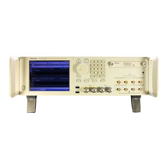
Operating basics Front-panel connectors AWG70000A Series Installation and Safety Instructions... - Page 28 The marker LEDs light when the corresponding channel is enabled and the outputs are electrically connected. Marker LEDs are always white. AWG70002A – CH1 and CH2 Markers Two USB connectors. When OFF is lighted, the front USB connectors have been disabled from the Utilities >...
-
Page 29: Rear-Panel Connectors
USB Host Four USB Host connectors (type A) to connect devices such as a mouse, keyboard, or other USB devices. Tektronix does not provide support or device drivers for USB devices other than the supplied mouse and keyboard. USB Device USB Device connector (type B) interfaces with the TEK-USB-488 GPIB to USB adapter and provides connectivity with GPIB based control systems. -
Page 30: Getting Acquainted With Your Instrument
Operating basics Getting acquainted with your instrument Touchscreen interface The arbitrary waveform generator offers a touchscreen interface that you can use to access all features and controls. Enable or disable the touchscreen interface by pushing the front-panel Touchscreen button. When the touchscreen is in the Off state, the LED is lighted. On-screen menus are then operated via the front panel, keyboard, or mouse. - Page 31 Operating basics Buttons/Keys Description General purpose knob The general purpose knob is used to increment or decrement values when a setting is enabled (selected) for change. Push the knob to toggle the Fine mode on and off, increasing or decreasing the change resolution of the general purpose knob.
-
Page 32: Awg Mode General Overview
Operating basics AWG mode general overview The following illustration and table provide a high-level overview of the AWG mode. Screen element Description 1. Play/Stop button Starts and stops playing the waveform. The Play button icon changes to indicate the play status of the waveform. - Page 33 Operating basics Screen element Description 4. Mode selection Switches the instrument mode between AWG (arbitrary waveform generator) and Functions (basic waveshape generator). Mode selection is available from the Home tab in both the AWG mode and the Functions mode. 5. Workspace The workspace area shows the contents of the selected tab (such as: Home, Settings).
-
Page 34: Functions Mode General Overview
Operating basics Functions mode general overview The Functions interface provides you with a quick and easy way to generate simple types of waveforms. Refer to the following illustration and table for information on the key screen elements. Screen element Description 1. -
Page 35: Run State Control
Operating basics Screen element Description 7. Status bar The status bar displays various user messages and status indicators. 8. Toolbar Tools are used to: Display the instrument help. ■ Restore the display to the default layout. ■ Restore the default setup. ■... -
Page 36: Run Mode
Operating basics Run state status indicators (front-panel Play/Stop button). The front-panel play button changes appearance to indicate the waveform play out status. Below are the various indicators. Indicator Description Not lighted Stopped (or idle) with no waveforms being played. Green Currently playing a waveform. -
Page 37: Preferences
Operating basics Preferences Use the Preferences to set certain instrument characteristics that are retained for each subsequent power on. The Preferences screen also contains the instrument’s security settings. In the toolbar, go to Utilities > Preferences to access user preferences. Brightness controls. -
Page 38: Restoring Instrument Operating System And Product Software
To restore or update the AWG product software, you need to download the current version from the Tektronix web site. NOTE. Restoring or updating the AWG product software does not require that you restore the Windows operating system. -
Page 39: Specifications
Specifications and Performance Verification manual. General characteristics Waveform memory AWG70001A 2,000,000,000 points AWG70001A (Option 01) 16,000,000,000 points AWG70002A 2,000,000,000 points, each channel AWG70002A (Option 01) 8,000,000,000 points, each channel Minimum waveform size AWG70001A 4800 points AWG70002A 2400 points Waveform granularity AWG70001A... -
Page 40: Sample Clock Generator Characteristics
Sample clock generator characteristics Sample rate Range AWG70001A (Option 150) 1.49 kS/s to 50 GS/s AWG70002A (Option 225) 1.49 kS/s to 25 GS/s AWG70002A (Option 216) 1.49 kS/s to 16 GS/s AWG70002A (Option 208) 1.49 kS/s to 8 GS/s Resolution... -
Page 41: Analog Ac Output (Awg70001A With Option Ac)
Specifications Analog AC output (AWG70001A with Option AC) Output connector Aeroflex/Weinschel Planar Crown Universal Connector System with SMA female adapter Number of analog AC outputs AWG70001A: 1 Type of outputs single ended Output impedance 50 Ω Amplitude Range (for a CW signal at Filter path Description specified frequencies in each... -
Page 42: Marker Outputs
Specifications Marker outputs Output connector SMA (front panel) Number of outputs AWG70001A AWG70002A Type of outputs (+) and (-) complementary ON/OFF control Independent control for each marker Impedance 50 Ω Output voltage Independent control for each marker Amplitude range 0.5 V to 1.4 V... -
Page 43: Auxillary Outputs
Specifications Auxillary outputs 10 MHz reference out Connector SMA (rear panel) Output impedance 50 Ω, AC coupled Amplitude +4 dBm ±2 dBm Frequency 10 MHz ±(1 ppm + aging) Synchronization clock output Frequency 1/80 of the clock output Amplitude 1.0 V ±150 mV into 50 Ω... -
Page 44: Computer Outputs
Specifications Auxiliary inputs (cont.) Connector SMA (rear panel) Input impedance 50 Ω, AC coupled Computer outputs Computer outputs Video output 1 VGA port on rear panel eSATA 1 port on rear panel, 1.5 Gbps USB 2.0 ports Type A, (6 total: 2 on front panel, 4 on rear panel) GPIB Interface Available as an optional accessory that connects to the USB device and USB Host ports with the TEK-USB-488 GPIB to USB Adapter... -
Page 45: Compliance Information
■ EN 61000-3-2.. AC power line harmonic emissions EN 61000-3-3.. Voltage changes, fluctuations, and flicker Mfr. Compliance Contact. Tektronix, Inc. PO Box 500, MS 19‐045 Beaverton, OR 97077, USA www.tek.com Australia / New Zealand Declaration of Conformity – EMC Complies with the EMC provision of the Radiocommunications Act per the following standard, in accordance with ACMA: CISPR 11. -
Page 46: Safety Compliance
Compliance Information Safety compliance This section lists the safety standards with which the product complies and other safety compliance information. EU declaration of conformity – low voltage Compliance was demonstrated to the following specification as listed in the Official Journal of the European Union: Low Voltage Directive 2006/95/EC. -
Page 47: Environmental Compliance
Directives 2012/19/EU and 2006/66/EC on waste electrical and electronic equipment (WEEE) and batteries. For information about recycling options, check the Tektronix Web site (www.tek.com/productrecycling). Perchlorate materials. This product contains one or more type CR lithium batteries. According to the state of California, CR lithium batteries are classified as perchlorate materials and require special handling. - Page 48 Compliance Information AWG70000A Series Installation and Safety Instructions...
- Page 49 Index Disable outputs, 19, 20 10 MHz Reference Output Disconnect outputs, 19, 20 rear-panel, 15 Display properties, 11 Documentation, vii About my AWG, 10 AC output front-panel connector, 14 Enable channel, 18, 20 Accessories, 1 Environmental requirements, 4 All outputs off, 19, 20 error indication, 21 All Outputs Off button, 17 eSATA port...
- Page 50 Index Play a waveform, 18 upgrades, 10 Play button, 18, 20 Play/Stop button, 16, 18, 20 Play/Stop button (screen) LAN connector green with sine wave, 21 rear-panel, 15 green with T symbol, 21 LED color Analog outputs, 14 no light, 21 marker outputs, 14 red, 21 Lock screen, 23...
- Page 51 Index Sync to Hub Replaceable parts, 3 rear-panel, 15 Requirements environmental, 4 operating, 4 power supply, 4 TekVISA installation, 24 Restore Tools panel, 19, 21 AWG product software, 24 Touch screen, 16 Windows operating system, 24 Touchscreen button, 17 Restore Default Layout, 19, 21 Trigger controls Restore default setup, 19, 21 Screen interface, 19...
- Page 52 Index AWG70000A Series Installation and Safety Instructions...
Need help?
Do you have a question about the AWG70002A and is the answer not in the manual?
Questions and answers