Sign In
Upload
Manuals
Brands
Tektronix Manuals
Inverter
AWG710B
Tektronix AWG710B Waveform Generator Manuals
Manuals and User Guides for Tektronix AWG710B Waveform Generator. We have
1
Tektronix AWG710B Waveform Generator manual available for free PDF download: User Manual
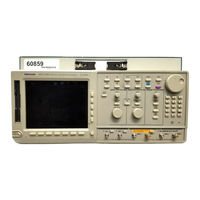
Tektronix AWG710B User Manual (580 pages)
4 GS/s / 4.2 GS/s Arbitrary Waveform Generator
Brand:
Tektronix
| Category:
Inverter
| Size: 9 MB
Table of Contents
Table of Contents
5
Preface
25
Related Manuals
25
Getting Started
29
Table 1-1: AWG710&AWG710B Waveform Editors
30
Getting Started
32
Incoming Inspection
32
Table 1-2: Power Cord Options
33
Table 1-3: Language Options
33
Table 1-4: Standard Accessories
34
Table 1-5: Optional Accessories
34
Options
36
Installation
38
Table 1-6: Fuse and Fuse Cap Part Numbers
39
Table 1-7: Power Cord Identification
40
Figure 1-1: Rear Panel Power Switch, Fuse Holder, and Power Connector
41
Figure 1-2: Location of the ON/STBY Switch
42
Repackaging for Shipment
44
Operating Basics
47
Figure 2-1: Front Panel Controls (AWG710)
48
Figure 2-2: Front Panel Controls (AWG710B)
49
Figure 2-3: Front Panel Keypad Area
50
Figure 2-4: Front Panel Trigger and Output Controls
51
Figure 2-5: Rear Panel Signal and Power Connectors (AWG710)
52
Figure 2-6: Rear Panel Signal and Power Connectors (AWG710B)
53
Operating Basics
54
Figure 2-7: Menu Buttons, Bezel Menu Buttons, and the CLEAR MENU Button
54
Menu Operations
54
Figure 2-8: Bottom and Side Menus
55
Figure 2-9: Pop-Up Menu Example
56
Table 2-1: Side Menu Elements
56
Figure 2-10: Dialog Box Example
57
Figure 2-11: Knob Icon Displayed in Status Display Area
58
Numeric Input
58
Figure 2-12: Keypad Buttons
59
Figure 2-13: Three Type of Input Text Dialog Boxes
60
Figure 2-14: Shortcut Controls
61
Table 2-2: Text Input Button Functions
61
Table 2-3: Shortcut Controls
62
File Management
63
Table 2-4: AWG710&AWG710B Arbitrary Waveform Generator File Types
63
Table 2-5: Drive and Directory Menus
64
Figure 2-15: Files and Directories with Read Only Attribute
67
Figure 2-16: Input Filename Dialog Box
67
Table 2-6: Waveform Record Length Adjustment Messages
68
Figure 2-17: File List Window Examples in Which Quick View Is Available
70
Figure 2-18: Viewing a File by Quick View Function
71
Editor Overview
72
Table 2-7: Editors
72
Figure 2-19: Main Edit Screen
73
Table 2-8: Edit Screen Bottom Menu Buttons
73
Figure 2-20: Edit Top Level Menu Screen with Edit Side Menu
74
Figure 2-21: Editor Screen Elements
75
Table 2-9: Edit Side Menu Buttons
75
Figure 2-22: Cursors and Edit Area
76
Figure 2-23: Multiple Editor Windows
77
Figure 2-24: Main Setup Screen (Except Option02)
80
Setup Overview
80
Table 2-10: Setup Screen Parameter Icons
81
Table 2-11: Setup Bottom Menu Buttons
81
Figure 2-25: Select File Dialog on the Load Menu
82
Figure 2-26: Viewing a File in the Setup Screen
83
Table 2-12: Setup Output Parameter Operations
84
Table 2-13: Run Modes
87
Theory of Operation
87
Table 2-14: Extended Operation
88
Figure 2-27: AWG710 Block Diagram
89
Figure 2-28: AWG710B Block Diagram
90
Figure 2-29: Relationship between Memory Address Control and
91
Signal Edit Process
92
Table 2-15: Editors
93
Tutorials
95
Figure 2-30: Cable Connection between AWG710&AWG710B Arbitrary Waveform Generator and Digital Storage Oscilloscope
96
Figure 2-31: Initial Screen (Right Figure: Option02)
96
Figure 2-32: System Utility Screen
97
Tutorial 1: Instrument Setup
97
Tutorial 2: Loading and Outputting a Sample Waveform
99
Figure 2-33: the Select File List
100
Figure 2-34: Viewing a Waveform Loaded into Memory
101
Tutorial 3: Creating and Editing Standard Function Waveforms
102
Figure 2-35: Waveform Editor Initial Screen
103
Figure 2-36: the Standard Function Dialog Box
104
Figure 2-37: Standard Sine Wave Function Created in the Waveform Editor
105
Figure 2-38: Waveform Created with the Multiply Operation
106
Figure 2-39: File Name Input Dialog Box
107
Tutorial 4: Editing a Waveform Using Quick Editor
109
Figure 2-40: Waveform in the Waveform Editor
110
Figure 2-41: Waveform Edit in Quick Editor
111
Tutorial 5: Using the Equation Editor
113
Figure 2-42: Viewer Displaying Compiled Waveform
115
Tutorial 6: Creating and Running Waveform Sequences
116
Table 2-16: Waveforms to be Used in Sample Sequences
117
Figure 2-43: Waveforms Created at the same Time in Three Windows
118
Figure 2-44: Initial Sequence Table
119
Table 2-17: Sequence Table Contents in Subseq.seq
120
Figure 2-45: Example of Sequence (Subseq.seq)
121
Table 2-18: Sequence Table Contents in Mainseq.seq
122
Figure 2-46: Screen for Setting Jump Mode
123
Figure 2-47: Screen for Setting Event Jump
124
Figure 2-48: Setup of Goto <N
125
Figure 2-49: Example of Sequence (Mainseq.seq)
126
Figure 3-1: Overview of AWG710&AWG710B Arbitrary Waveform
131
Reference
131
Table 3-1: AWG710&AWG710B Arbitrary Waveform Generator Main Menus
132
Reference
133
Menu Structures
133
Setup Menu Hierarchy
134
EDIT Menu Hierarchy
143
APPL Menu Hierarchy
156
Utility Menu Hierarchy
160
The Setup Menu Screen
163
Setup Menu Screen Elements
163
Figure 3-2: Setup Main Screen (Except Option 02)
163
Table 3-2: Waveform Parameter Icons
164
Table 3-3: Setup Bottom Menu Buttons
164
Table 3-4: Status Area
165
The Waveform/Sequence Menu
166
The Vertical Menu
168
The Horizontal Menu
170
Figure 3-3: 1/4 CLOCK out Output Format
171
Table 3-5: Clock Signal Output Timing
171
Figure 3-4: 1/4 CLOCK out Connection Examples
172
The Run Mode Menu
174
Figure 3-5: Run Mode and Current Status
174
The Trigger Menu
176
Table 3-6: External Trigger Signal Requirements
176
Figure 3-6: Trigger Slope and Trigger Level
177
The Save/Restore Menu
178
The Extended Operation Menu
180
Waveform, Pattern and Sequence Waveform Output
181
Figure 3-7: Waveform Output Sequence Example
181
Table 3-7: Instrument Run State and State Messages
183
The Graphical Waveform Editor
185
Editor Screen Elements
185
Figure 3-8: Waveform Editor Initial Screen
185
Table 3-8: Waveform Editor Screen Elements
186
Table 3-9: Waveform Editor Bottom Menu
187
The File Menu
188
The Operation Menu
189
Figure 3-9: Standard Function Waveform Dialog Box
190
Table 3-10: Standard Function Waveform Dialog Box Parameters
190
Figure 3-10: Register Value and Tap Setting Example
196
Figure 3-11: Shift Register Generator Dialog Box
197
Table 3-11: Shift Register Generator Dialog Box Setting Parameters
197
Figure 3-12: Set Pattern Dialog Box
198
Table 3-12: Set Pattern Dialog Box Parameters
199
The Tools Menu
202
Table 3-13: Mathematical Function Commands
202
Figure 3-13: Waveform Compare Operation Example
205
Table 3-14: Compare Dialog Box Parameters
205
Table 3-15: Convolution Dialog Box Parameters
206
Table 3-16: Correlation Dialog Box Parameters
207
Figure 3-14: Digital Filter Dialog Box
208
Table 3-17: Digital Filter Dialog Box Parameters
208
Table 3-18: Re-Sampling Dialog Box Parameters
209
Figure 3-15: XY View Dialog Box
210
Table 3-19: XY View Dialog Box Parameters
210
The Zoom/Pan Menu
211
Table 3-20: Zoom/Pan Side Menu Buttons
211
The Window Menu
212
The Settings Menu
212
Figure 3-16: Settings Dialog Box
213
Table 3-21: Setup Window Parameters
213
Table 3-22: Setup General Parameters
214
The Pattern Editor
215
About Waveform and Pattern Files
215
Starting the Pattern Editor
216
Figure 3-17: Pattern Editor Initial Screen
216
Table 3-23: Pattern Editor Screen Elements
216
The File Menu
217
The Operation Menu
217
The Tools Menu
217
Table 3-24: Pattern Editor Bottom Menu
217
Figure 3-18: Code Convert Dialog Box and Side Menu
218
Figure 3-19: Code Conversion Table
219
Table 3-25: Code Conversion Commands
219
Table 3-26: Code Conversion Parameters
219
The Zoom/Pan Menu
221
The Window Menu
221
The Settings Menu
221
The Undo! Command
221
Selecting Data Bits to Edit
222
Figure 3-20: Operating Data Bits (Scope)
222
Defining Edit Area
223
Creating a Pattern
224
Figure 3-21: Area Cursors
224
Creating Standard Patterns
225
Figure 3-22: Counter Dialog Box
225
Table 3-27: Patterns to be Selected in Counter Dialog Box
225
Inserting Data from Files
226
Set Pattern
226
Figure 3-23: Set Pattern Dialog Box
226
Table 3-28: Set Pattern Dialog Box Parameters
227
Quick Editing
229
Screen Display
229
Quick Edit Mode
230
Quick Edit Mechanism
230
Figure 3-24: a Waveform Example under Quick Editing
230
About Smoothing
231
Quick Controls
231
Figure 3-25: Controls for Quick Editing
231
Starting Quick Edit
232
Exiting Quick Edit
233
Setting Parameters
233
Moving the Cursor
234
Renewing Edit Buffer
234
About Undo
234
The Table Editor
235
Opening the Table Editor
235
Editing the Table Data
236
Figure 3-26: Table Editor Window
236
The Equation Editor
239
Starting the Equation Editor
240
Figure 3-27: Equation Editor Window
240
Table 3-29: Equation Editor Screen Elements
240
Using the Equation Editor
241
Table 3-30: Equation Editor Bottom Menu
241
Table 3-31: Front-Panel Equation Editor Controls
242
Figure 3-28: Text Selection (Example)
243
Entering Keywords and Functions
244
Table 3-32: Control Keys from the External Keyboard
244
Compiling Equations
245
Figure 3-29: File List Listing Two Waveforms Created
246
The Sequence Editor
247
Starting the Sequence Editor
247
Figure 3-30: Sequence Editor Initial Screen
247
Table 3-33: Sequence Table Columns
248
Table 3-34: Sequence Editor Bottom Menu
249
Sequence Table Editing
250
Sequence Table Fields
252
Figure 3-31: EVENT in Connector
254
Figure 3-32: Event Signal Timing and Strobe
257
Figure 3-33: Compiling and Storing Sequences and Subsequences
259
The APPL Menu
261
Disk Application
261
Figure 3-34: Outline Flow for Producing HDD Reading Test Signal
261
Figure 3-35: Disk Application Initial Screen
262
Figure 3-36: Writer Data Menu
262
Figure 3-37: Isolated Pulse Menu
263
Figure 3-38: Execution of Superpose
263
Table 3-35: Pre-Defined Patterns
264
Table 3-36: Code Conversion
264
Table 3-37: Superpose Parameters
268
Network Application
270
Figure 3-39: Outline Flow for Producing Network Test Read Signal
270
Figure 3-40: Network Application Initial Screen
270
Figure 3-41: Side Menu will Change after Selecting a Standard
271
Figure 3-42: Side Menu for Selecting the Isolated Pulse
272
Figure 3-43: Execution of Superposing
273
Table 3-38: Pre-Defined Patterns
274
Table 3-39: Code Conversion
274
Table 3-40: Network Parameters
275
Jitter Composer Application
277
Figure 3-44: Outline Flow for Jitter Waveform Creation
277
Figure 3-45: Jitter Composer Application Initial Screen
278
Figure 3-46: Input Data Menu
278
Figure 3-47: a Pre-Defined Pattern was Selected as an Input Data
279
Figure 3-48: Jitter Profile Menu
279
Figure 3-49: Execution of Jitter Composer
280
Table 3-41: Pre-Defined Patterns
281
Table 3-42: Jitter Composer Parameters
282
Figure 3-50: Jitter Parameters and Jitter Waveform
283
The UTILITY Window
285
External Keyboards
285
Setting General Purpose Knob Direction
286
Table 3-43: External Keyboard Edit Operations
286
Formatting a Floppy Disk
287
Displaying Disk Usage
287
Screen Display Enable/Disable
288
Focused Color
288
Displaying Instrument Status
288
Internal Clock (Date and Time)
289
Resetting the Instrument
289
Connecting to a GPIB Network
290
Figure 3-51: GPIB Setup Screen Menu
291
Ethernet Networking
292
Figure 3-52: Network Setup Screen Menu
293
Figure 3-53: Message Box to Indicate the Establishment of Communication
295
Figure 3-54: Network Status Screen
295
Figure 3-55: UTILITY Screen Mounting Remote File System
296
Figure 3-56: Drive Selections in EDIT Menu
298
Table 3-44: Available FTP Commands
299
Hardcopy
300
Figure 3-57: Hardcopy Setup Screen
301
Calibration and Diagnostics
302
Figure 3-58: Hardcopy Complete Message Box
302
Figure 3-59: Calibration and Diagnostic Screen
303
Figure 3-60: Status Message Box (Except Option02)
304
Table 3-45: Diagnostic Categories and Error Codes
306
Upgrading the System Software
309
Capturing Waveforms
311
Possible Instruments
311
Basic Concept on Communication for Capturing
311
Procedures for Capturing Waveforms
312
Figure 3-61: Source Instrument Selection Dialog Box
312
Figure 3-62: Source Instrument Selection under Others
313
About Transferred Files
314
Waveform Programming Language
315
Command Syntax
315
Table 3-46: BNF Symbols and Meanings
315
User-Defined Variables
316
Waveform Files
317
Command Descriptions
319
Bpf( )
319
Brf( )
320
Code( )
321
Conv( )
321
Copy( )
322
Corr( )
322
Data( )
323
Delete( )
324
Diff( )
324
Expand( )
325
Extract( )
325
For (Control Statement)
326
Hpf( )
327
If (Control Statement)
328
Integ( )
328
Join( )
329
Lpf( )
329
Math Functions
330
Table 3-47: Programming Language Math Functions
330
Math Operators
332
Table 3-48: Math Operators
332
Norm( )
333
Rename( )
334
Variables (Predefined)
335
Table 3-49: Predefined Variables
335
Write( )
336
Programming Examples
337
Figure 3-63: Waveforms Generated from the Example 1 Equation
338
Figure 3-64: Waveform Generated by the Example 2 Equation
339
Figure 3-65: Waveforms Generated by the Example 3 Equation
340
Figure 3-66: Sequence Generated by the Example 3 Equation
341
Figure 3-67: Source Waveform and those Generated by the Example 4 Equation
342
Figure 3-68: Noise Waveforms after Filtering
343
Figure 3-69: Noise Waveforms before (Upper) and after (Lower) 7-Point Smoothing
345
Figure 3-70: Gaussian Noise and Ramp Waveforms
347
File Conversion
349
Import
349
Export
351
Convert between Waveform and Pattern
351
Executing File Conversion
352
Figure 3-71: Screen and Side Menu Buttons for Importing and Exporting
352
Figure 3-72: Select the Conversion Type Dialog Box
352
File Management
355
Command Summary
355
Path Name
355
Table 3-50: File Utility Commands
355
File Operations
356
Table 3-51: Special Symbols Used for Expressing File Path
356
File Operation in Double Windows
360
Figure 3-73: Double Windows
360
Table 3-52: File Operation in Double Windows
361
Figure 3-74: Overwrite Confirmation
362
Table 3-53: Confirmation Selection for Copy-All and Move-All Operations
362
FG Mode
363
Figure 3-75: Outline Flow for Producing Function Generator Signal
363
Figure 3-76: FG Mode Screen (Except Option 02)
363
Change the Generator Mode
364
Figure 3-77: Change the Generator Mode (Except Option 02)
364
Figure 3-78: Waveform Type
365
Parameters
366
Figure 3-79: Output Parameters (Except Option 02)
366
Table 3-54: Output Frequency and Filter Cut-Off Frequency (Except Option02)
367
Figure 3-80: Marker Pattern
368
Table 3-55: Predefined Marker Signal
368
Table 3-56: Output Frequency and Waveform Length
369
Figure 3-81: Pulse Sub-Side Menu (Except Option 02)
370
Waveform Mixing Mode
371
Figure 3-82: Outline Flow for Producing Mixed Signal
371
Figure 3-83: Waveform Mixing Mode Screen
371
Change the Generator Mode
372
Figure 3-84: Change the Generator Mode
372
File
373
Table 3-57: Combination of the File Type
373
Waveform Mixing Parameters
375
Update
376
Save/Restore Setup
377
Operation Flow
377
Synchronous Operation Mode (AWG710B Only)
379
Figure 3-85: Outline Flow for Producing Synchronous Operation
379
Restrictions
380
Connecting the Cables
380
Figure 3-86: Synchronous Operation Cable Connection
381
Change the Generator Mode
382
Figure 3-87: Change the Generator Mode
382
Setup Screen
383
Figure 3-88: Synchronous Operation Mode Screen
383
Setting a Slave IP Address
384
Testing the Network Connection
384
Table 3-58: Difference between AWG Mode and
384
Connection with Slave
385
Error Messages on Connection
385
Table 3-59: Error/Warning Messages
385
Trigger Timing Calibration
386
Save/Restore Setup
387
Operation Flow
387
Specifications (AWG710B
391
Electrical Specification
392
Table A-1: Operation Modes
392
Table A-2: Extended Operation
392
Table A-3: Arbitrary Waveforms
392
Table A-4: Clock Generator
393
Table A-5: Internal Trigger Generator
393
Table A-6: Main Output
393
Table A-7: Filter (Except Option 02
395
Table A-8: Auxiliary Outputs
395
Table A-9: Marker Output Period Jitter
397
Table A-10: Marker Output Cycle to Cycle Jitter
397
Table A-11: VCO Output Period Jitter
397
Table A-12: VCO Output Cycle to Cycle Jitter
397
Table A-13: Auxiliary Inputs
398
Figure A-1: Signal Timing
399
Figure A-2: Gated Mode
400
Figure A-3: Enhanced Mode
401
Figure A-4: Sequence 2
402
Figure A-5: Sequence 3
403
Figure A-6: 3-1. Sequence 4
404
Figure A-7: the Cable Connection between Units in Synchronous Operation
405
Figure A-9: Output Part Equivalent Circuit of MARKE
407
Table A-14: Event Input
408
Table A-15: 10 Mhz Reference Clock Input
408
Table A-16: External Clock Input
408
Table A-17: C Input
409
Table A-18: T Input
409
Table A-19: Function Generator (FG)
410
Table A-20: Display
411
Table A-21: AC Line Power
411
Table A-22: Timer
411
Table A-23: Interface Connectors
411
Table A-24: Installation Requirement
412
Table A-25: Maintenance Requirement
412
Table A-26: Environmental
412
Table A-27: Mechanical
413
Figure A-10: Dimensions
414
Certification and Compliances
415
Table A-28: Certifications and Compliances
415
Table A-29: Installation Category and Pollution Degree Descriptions
416
Specifications (AWG710
417
Electrical Specification
418
Table A-30: Operation Modes
418
Table A-31: Arbitrary Waveforms
418
Table A-32: Clock Generator
419
Table A-33: Internal Trigger Generator
419
Table A-34: Main Output
419
Table A-35: Filter (Except Option 02)
421
Table A-36: Auxiliary Outputs
421
Table A-37: Period Jitter
422
Table A-38: Cycle to Cycle Jitter
422
Table A-39: Auxiliary Inputs
423
Figure A-11: Signal Timing
424
Table A-40: Event Input
425
Table A-41: 10 Mhz Reference Clock Input
425
Table A-42: Function Generator (FG)
426
Table A-43: Display
427
Table A-44: AC Line Power
427
Table A-45: Timer
427
Table A-46: Interface Connectors
427
Table A-47: Installation Requirement
428
Table A-48: Environmental
428
Figure A-12: Dimensions
429
Table A-49: Mechanical
429
Certification and Compliances
430
Table A-50: Certifications and Compliances
430
Table A-51: Installation Category and Pollution Degree Descriptions
431
Performance Verification (AWG710B
433
Conventions
433
Self Tests
434
Figure B-1: Diagnostic Menu
435
Figure B-2: Calibration Result Message Box (Except Option 02)
437
Table B-1: Performance Test Items
438
Performance Tests
438
Performance Tests
439
Table B-2: Test Equipment
439
Figure B-3: EVENT in Connector Pins and Signals and
441
Figure B-4: Loading File; Selecting Storage Drive
441
Table B-3: Waveforms and Sequences in Performance Check Disk
443
Operating Mode Tests
445
Figure B-5: Cont Mode Initial Test Hookup
445
Figure B-6: Triggered Mode Initial Test Hookup
447
Figure B-7: Relationship between Trigger Signal and Waveform Output
448
Figure B-8: Relationship between Gate Signal and Waveform Output
450
Amplitude and Offset Accuracy Tests (Normal Out), (Except Option 02
451
Figure B-9: Amplitude Accuracy Initial Test Hookup
451
Amplitude, Offset Accuracy and Rise Time Tests (Direct da Out), (Except Option 02
455
Figure B-10: Direct da Output Amplitude Accuracy Initial Test Hookup
455
Figure B-11: Direct da Output Pulse Rise Time Initial Test Hookup
457
Amplitude, Offset Accuracy and Rise Time Tests (for Option 02
459
Figure B-12: Option02 Output Amplitude Accuracy Initial Test Hookup
459
Figure B-13: Optipn02 Output Pulse Rise Time Initial Test Hookup
461
Pulse Response Tests (Normal Out), (Except Option 02
463
Figure B-14: Pulse Response Initial Test Hookup
463
Trigger Input Tests
465
Figure B-15: Trigger Input Initial Test Hookup
465
Figure B-16: Trigger Signal and Waveform Output (+5 V Check 1)
467
Figure B-17: Trigger Signal and Waveform Output (+5 V Check 2)
467
Figure B-18: Trigger Signal and Waveform Output (-5 V Check 1)
468
Figure B-19: Trigger Signal and Waveform Output (-5 V Check 2)
468
Event Input and Enhanced Mode Tests
469
Figure B-20: Event Input and Enhanced Mode Initial Test Hookup
469
Figure B-21: Waveform While All Ground Disclosure Switches Are Open
471
Figure B-22: Waveform Output When the SW1 Is Closed
471
Figure B-23: Waveform Output When SW2 Is Closed
472
Figure B-24: Waveform Output When the SW3 Is Closed
472
Figure B-25: Waveform Output When SW4 Is Closed
473
Figure B-26: Waveform Output When SW6 Is Closed
474
Figure B-27: Waveform Output When SW7 Is Closed
474
Figure B-28: Waveform Output When SW8 Is Closed
475
Figure B-29: Initial Waveform Output
476
Figure B-30: DC Waveform Output When the SW5 Is Closed
476
External Clock Input and VCO out Output Tests
478
Figure B-31: Trigger Input Initial Test Hookup
478
VCO out Output Frequency and 10 Mhz Reference Input Tests
480
Figure B-32: VCO out Outputfrequency and 10 Mhz Reference Input
480
Marker Output Tests
482
Figure B-33: Marker Output Initial Test Hookup
482
Synchronous Operation Tests
484
Figure B-34: Synchronous Operation Test Hookup
484
Performance Verification (AWG710
487
Conventions
487
Self Tests
488
Figure B-35: Diagnostic Menu
489
Figure B-36: Calibration Result Message Box (Except Option 02)
491
Table B-4: Performance Test Items
492
Performance Tests
493
Table B-5: Test Equipment
493
Figure B-37: EVENT in Connector Pins and Signals and Ground Closure
494
Connector
494
Figure B-38: Loading File; Selecting Storage Drive
495
Table B-6: Waveforms and Sequences in Performance Check Disk
496
Operating Mode Tests
498
Figure B-39: Cont Mode Initial Test Hookup
498
Figure B-40: Triggered Mode Initial Test Hookup
500
Figure B-41: Relationship between Trigger Signal and Waveform Output
501
Figure B-42: Relationship between Gate Signal and Waveform Output
503
Amplitude and Offset Accuracy Tests (Normal Out), (Except Option 02
504
Figure B-43: Amplitude Accuracy Initial Test Hookup
505
Amplitude, Offset Accuracy and Rise Time Tests (Direct da Out), (Except Option 02
509
Figure B-44: Direct da Output Amplitude Accuracy Initial Test Hookup
509
Figure B-45: Direct da Output Pulse Rise Time Initial Test Hookup
511
Amplitude, Offset Accuracy and Rise Time Tests (for Option 02
513
Figure B-46: Option02 Output Amplitude Accuracy Initial Test Hookup
513
Figure B-47: Optipn02 Output Pulse Rise Time Initial Test Hookup
515
Pulse Response Tests (Normal Out), (Except Option 02
517
Figure B-48: Pulse Response Initial Test Hookup
517
Trigger Input Tests
519
Figure B-49: Trigger Input Initial Test Hookup
519
Figure B-50: Trigger Signal and Waveform Output (+5 V Check 1
521
Figure B-51: Trigger Signal and Waveform Output (+5 V Check 2
521
Figure B-52: Trigger Signal and Waveform Output (-5 V Check 1
522
Figure B-53: Trigger Signal and Waveform Output (-5 V Check 2
522
Event Input and Enhanced Mode Tests
523
Figure B-54: Event Input and Enhanced Mode Initial Test Hookup
523
Figure B-55: Waveform While All Ground Disclosure Switches Are Open
525
Figure B-56: Waveform Output When the SW1 Is Closed
525
Figure B-57: Waveform Output When SW2 Is Closed
526
Figure B-58: Waveform Output When the SW3 Is Closed
527
Figure B-59: Waveform Output When SW4 Is Closed
527
Figure B-60: Initial Waveform Output
528
Figure B-61: DC Waveform Output When the SW5 Is Closed
529
1/4 Clock Frequency and 10 Mhz Reference Input Tests
530
Figure B-62: 1/4 Clock Frequency and 10 Mhz Reference Input
530
Marker Output Tests
532
Figure B-63: Marker Output Initial Test Hookup
532
Inspection and Cleaning
535
Table C-1: External Inspection Check List
535
Sample Waveforms
537
Table D-1: Waveform and Equation Files in the Sample Disk
537
Waveform File Descriptions
538
Table D-2: Gaussian Pulse
538
Table D-3: Lorentz Pulse
539
Table D-4: Sampling Function sin(X)/X Pulse
539
Table D-5: Squared Sine Pulse
540
Table D-6: Double Exponential Pulse
540
Table D-7: Nyquist Pulse
541
Table D-8: Linear Frequency Sweep
542
Table D-9: Log Frequency Sweep
542
Table D-10: Amplitude Modulation
543
Table D-11: Frequency Modulation
543
Table D-12: Pulse Width Modulation
544
Table D-13: Pseudo-Random Pulse
544
Table D-14: Waveform for Magnetic Disk Signal
544
Table D-15: Isolated Pulse for Disk Application
545
Table D-16: Isolated Pulse for Disk Application
545
Table D-17: Isolated Pulse for Disk Application
546
Table D-18: Isolated Pulse for Network Application
546
Table D-19: Isolated Pulse for Network Application
547
Table D-20: Isolated Pulse for Network Application
547
Table D-21: Isolated Pulse for Network Application
547
Table D-22: Isolated Pulse for Network Application
548
Table D-23: Isolated Pulse for Network Application
548
File Transfer Interface Outline
549
Figure E-1: File Transfer Interface Outline
549
Sampling Theorem
551
Differentiation
551
Miscellaneous
551
Figure F-1: Equation Differentiation
552
Integration
553
Figure F-2: Equation Integration
553
Convolution
554
Correlation
555
Code Conversion
557
Figure F-3: Conversion Image Example
557
Examples
558
Sequence File Text Format
563
Header
563
Line Descriptions
563
Jump Settings
565
Examples
566
Index
567
Advertisement
Advertisement
Related Products
Tektronix AWG710
Tektronix AWG70002A
Tektronix AWG70001A
Tektronix AWG5000 Series
Tektronix AWG7000 Series
Tektronix AWG5200 Series
Tektronix AFG3101
Tektronix AFG3052C
Tektronix AFG3151C
Tektronix AFG31101
Tektronix Categories
Test Equipment
Measuring Instruments
Amplifier
Portable Generator
Printer
More Tektronix Manuals
Login
Sign In
OR
Sign in with Facebook
Sign in with Google
Upload manual
Upload from disk
Upload from URL