Tektronix AFG1022 Quick Start User Manual
Arbitrary / function generator, afg1000 series
Hide thumbs
Also See for AFG1022:
- Quick start user manual (61 pages) ,
- Technical reference (41 pages) ,
- Manual (78 pages)

Related Manuals for Tektronix AFG1022


Summary of Contents for Tektronix AFG1022
- Page 1 AFG1000 Series Arbitrary/Function Generator Quick Start User Manual *P077113001* 077-1130-01...
- Page 3 AFG1000 Series Arbitrary/Function Generator Quick Start User Manual www.tektronix.com 077-1130-01...
- Page 4 Copyright © Tektronix. All rights reserved. Licensed software products are owned by Tektronix or its subsidiaries or suppliers, and are protected by national copyright laws and international treaty provisions. Tektronix products are covered by U.S. and foreign patents, issued and pending. Information in this publication supersedes that in all previously published material.
- Page 5 Warranty Tektronix warrants that the product will be free from defects in materials and workmanship for a period of three (3) years from the date of original purchase from an authorized Tektronix distributor. If the product proves defective during this warranty period, Tektronix, at its option, either will repair the defective product without charge for parts and labor, or will provide a replacement in exchange for the defective product.
-
Page 7: Table Of Contents
Table of contents Preface ............................... iii Where to find more information ......................iii Conventions used in this manual ......................iii Service offerings ..........................iv Getting started ............................1 General features............................ 1 Before installation ..........................1 Standard accessories ..........................2 Operating requirements ........................3 Power the instrument on and off ...................... - Page 8 Table of contents Sweep a waveform ..........................35 Modulate a waveform ......................... 37 Generate a burst waveform ......................... 45 Copy channel setting .......................... 47 USB memory device .......................... 48 Utility menu ............................49 Save/recall instrument setup ....................... 52 Application examples ..........................54 Output the waveform created with ArbExpress ..................
-
Page 9: Preface
Preface This manual describes the installation and operation of Tektronix AFG1000 Series Arbitrary/Function Generator along with basic operations and concepts. The following instruments are supported by this manual: AFG1022 Arbitrary/Function Generator: 2-CH, 25 MHz bandwidth, 125 MS/s sampling rate, 14-bit vertical resolution... -
Page 10: Service Offerings
Tektronix provides service to cover repair under warranty and other services that are designed to meet your specific service needs. Tektronix warrants this product as describe in the warranty statement at the front of this manual. Tektronix technicians provide warranty service at most Tektronix service locations worldwide. -
Page 11: Getting Started
25 MHz / 60 MHz Function Generator 12.5 MHz / 30 MHz Pulse Generator 14-bit Arbitrary Waveform Generator 200 MHz Frequency Counter The following table describes some of the general features of your instrument. Feature AFG1022 AFG1062 Channel Sine 25 MHz 60 MHz Pulse 12.5 MHz... -
Page 12: Standard Accessories
Getting started Standard accessories Unpack the instrument and check that you received all items listed as Standard Accessories. Check the Tektronix Web site (www.tektronix.com) for the most current information. Standard accessories Description Tektronix part number AFG1000 Series Arbitrary/Function Generator Safety and... -
Page 13: Operating Requirements
Source voltage and frequency. 220 - 240 VAC, 100 - 120 VAC, 50/60 Hz, CATⅡ . requirements Power Consumption. AFG1022: Less than 28 W AFG1062: Less than 35 W WARNING. To reduce the risk of fire and shock, ensure that the mains supply voltage fluctuations do not exceed 10% of the operating voltage range. -
Page 14: Power The Instrument On And Off
Getting started Power the instrument on and off The following procedures show you how to apply power to the instrument and turn it on and off. Power on To turn apply power to the instrument and turn it on, do the following: CAUTION. -
Page 15: Change Instrument Settings At Power-On
Getting started Change instrument settings at power-on The default settings are restored when you power on the instrument. You can change the power-on settings to the last powered-off settings from the Utility menu using the following procedure. Push the front-panel Utility button. -
Page 16: Erase Waveforms From Memory
Getting started Erase waveforms from memory You can erase all waveforms from the instrument internal memory using the following procedure. Push the Arb panel button. Press Others. Press File browse to enter the file system. Use the general purpose knob to select INTER, and then press Enter. -
Page 17: Select A Local Language
Getting started Select a local language When you power on the instrument for the first time, English is selected by default. After you select a desired language, all the bezel menus, pop-up messages, and built-in help are displayed in the specified language. Push the front-panel Utility button. -
Page 18: Protect Your Instrument From Misuse
Getting started Protect your instrument from misuse Check input and output When connecting a cable, be sure to distinguish the input connector from the connectors output connectors to avoid making wrong connection. Locate the channel output on the front panel. Out1 means CH1 output and Out2 means CH2 output. -
Page 19: General Care
Getting started General care Protect the instrument from adverse weather conditions. The instrument is not waterproof. Do not store or leave the instrument where the display will be exposed to direct sunlight for long periods of time. CAUTION. To avoid damage to the instrument, do not expose it to sprays, liquids, or solvents. -
Page 20: Update Your Instrument Firmware
Utility menu and view the currently installed firmware version on the display screen. From a PC, visit www.tektronix.com and check if Tektronix offers a newer firmware version. Download and unzip the compressed zip file. Copy the designated firmware file onto a USB memory device. - Page 21 Getting started Press System. Press NextPage. Press Update firmware to enter file system. NOTE: If the USB memory device is not inserted, the Update firmware is disabled. Use the general purpose knob to select USBDEVICE, and then press Enter to enter USBDEVICE to browse files in the USB memory device.
- Page 22 Getting started The instrument displays a message telling you not to remove the USB device or power off the instrument until the update process is complete. The progress bar of the screen indicates the update process is in progress. NOTE: A firmware update usually takes approximately a minute.
-
Page 23: Equivalent Output Circuits
Getting started Equivalent output circuits The following illustrations show the equivalent output circuits: Legend for the following images: Output signals do not exceed ±10 V when the >50 Ω load impedance is used. A change to the load impedance (L) will affect the output window (maximum and minimum levels) for a sine waveform as follows. -
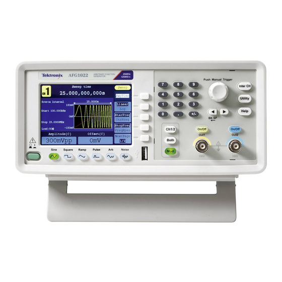
Page 24: Instrument Front Panel, Interface, And Rear Panel
Instrument front panel, interface, and rear panel Instrument front panel, interface, and rear panel Front panel overview The front panel is divided into easy-to-use functional areas. This section provides you with a quick overview of the front panel controls and the screen interface. 11 10 Item Description... -
Page 25: Parts Of The Screen Interface
Instrument front panel, interface, and rear panel Parts of the screen interface Item Description Bezel menu: When you push a front panel button, the instrument displays the corresponding menu on the right side of the screen. The menu shows the options that are available when you press the unlabeled bezel buttons directly to the right of the screen. -
Page 26: Default Setup
Instrument front panel, interface, and rear panel Default setup When you want to restore the instrument settings to the default values, use the front-panel Utility button as follows: Push the front-panel Utility button. Press System. Press Set_to Default. Select one of the following: Select to recall the default settings;... - Page 27 Instrument front panel, interface, and rear panel Default settings Default settings Menu/System Default setting Output configuration (Start Phase only available in AFG1062) Function Sine Frequency 1.000 000 000 kHz Start phase 0° Amplitude 1.000 V Offset 0 mV Symmetry (Ramp) 50.00% Duty (Pulse) 50.00%...
-
Page 28: Select Waveform
You can also create modulated waveforms using the Mod panel button and then Mod bezel button menus. The following table shows the combination of modulation type and the shape of the output waveform. Modulation, sweeping, and burst modes are only available in Ch1 on AFG1022. AFG1022 Sine,... - Page 29 Instrument front panel, interface, and rear panel Other available waveforms The following are examples of some other waveform types available in the Built-in Waveform menu. AFG1000 Series Quick Start User Manual...
-
Page 30: Select Run Mode
Push the Mod panel button, and then press one of the four Run Mode bezel buttons to select the instrument signal output method. Modulation, sweeping, and burst modes are only available in Ch1on the AFG1022. The default Run Mode is Continuous. -
Page 31: Adjust Waveform Parameters
Instrument front panel, interface, and rear panel Adjust waveform parameters When you turn on your instrument, the default output signal is a 1 kHz sine waveform with an amplitude of 1 V . In the following example, you can change the frequency and amplitude of the original output signal. -
Page 32: Channel Select
Instrument front panel, interface, and rear panel Channel select Push the front-panel Ch1/2 button to control the screen display. You can toggle between the two channels. Channel output On/Off To enable CH1 signal output, push the yellow front-panel On/Off button. To enable CH2 signal output, push the blue front-panel On/Off button. -
Page 33: Rear Panel
Instrument front panel, interface, and rear panel Rear panel The following illustration shows the rear panel connectors for the instrument. Item Description Power input: This is where you attached an appropriate power cord to supply power to the instrument. Fuse: Use the specified fuse according to the voltage scale. The rating of replaceable fuse: Voltage Fuse... -
Page 34: Operating Basics
Operating basics Quick tutorial: How to select a waveform and adjust parameters If you are a beginning user, follow the steps described here to select a waveform and adjust waveform parameters. 1. Push the power button to turn on the instrument. 2. -
Page 35: Quick Tutorial: How To Generate A Sine Waveform
Operating basics Quick tutorial: How to generate a sine waveform If you are a beginning user, follow the steps described here to learn how to generate a continuous sine waveform. Connect the power cord, and then push the front-panel power button to turn on the instrument. -
Page 36: Quick Tutorial: Instrument Help System
Operating basics Quick tutorial: Instrument help system The instrument help system allows you to access information about specific menu items and instrument functions when you need help. Access and navigate this help system using front panel buttons and knob; and then follow the on-screen instructions as they appear. -
Page 37: Generate A Pulse Waveform
Operating basics Generate a pulse waveform Push the front-panel Pulse button to display the Pulse screen. NOTE: All of the following s can be adjusted parameter using the numeric keypad or the general purpose knob. Press Width/DutyCyc and adjust the parameter as needed. -
Page 38: Generate A Built-In Waveform
Operating basics Generate a built-in waveform The instrument can output a built-in waveform that is stored in the internal memory. Push the front-panel Arb button. Adjust the parameters of arbitrary waveforms according to How to generate sine waveform (see page 25). Press Others. - Page 39 Operating basics Name Explanation Maths ExpRise Exponential rise function ExpDecay Exponential fall function Sinc Sinc function Tangent Cotan Cotangent SquareRoot Square root Square function HaverSine HaverSine function Lorentz Lorentz function Ln(x) Natural logarithm function Cubic function CauchyDistr Cauchy distribution BesselJ BesselI function BesselY BesselII function...
-
Page 40: Create/Save A User-Defined Waveform
Operating basics Create/save a user-defined waveform You can create a user-defined waveform, and save it in the internal memory or in an external USB memory device. Push the Arb panel button. Press Others. Press New to enter the Arb waveform edit menu. Press Points to set the number of waveform points to be edited. - Page 41 Operating basics 10. To save the waveform to internal memory, use the general purpose knob to select INTER and then press Enter. Use the front panel general purpose knob to select a USER file. Press Save. NOTE: The file size is displayed on the right side.
-
Page 42: Recall A User-Defined Waveform
Operating basics Recall a user-defined waveform You can recall an user-defined waveform that is stored in the internal memory or on a USB memory device. Push the Arb panel button. Press Others. Press File browse to enter the file system. To recall a waveform in the internal memory, use the general purpose knob to... - Page 43 Operating basics To copy a waveform file from the USB memory device to the internal memory: Follow the previous steps to recall the waveform from the USB memory device. Press Back to return to the upper directory. In the interface of selecting memory, use the general purpose knob to select INTER and then press...
-
Page 44: Generate Noise
Operating basics Generate noise Push the front-panel Noise waveform button. Use the general purpose knob or the numeric keypad to adjust Ampl, High, Offset and Low. NOTE: You cannot modulate, sweep, or burst a noise waveform. Generate DC Push the front-panel Arb button. -
Page 45: Sweep A Waveform
Operating basics Sweep a waveform The Sweep outputs a waveform with the output signal frequency varying linearly or logarithmically. Start frequency Stop frequency Sweep time Center frequency Frequency span To set sweep parameters, do the following: Select a waveform among sine, square, or ramp, and then push the front-panel Mod button. - Page 46 Operating basics Press Sweep Time to set the time between the start and stop frequency. Press Linear/Log to select the sweep type. Press StartFreq/ CtrFreq. Use the general purpose knob or the numeric keypad to set the start or the center frequency.
-
Page 47: Modulate A Waveform
Operating basics Modulate a waveform To output an AM waveform Select a waveform and then push the front-panel Mod button. In this example, use the sine waveform as an output waveform (carrier waveform). Press Mod. NOTE: You can only choose sine, square, ramp, or arb as a carrier waveform. - Page 48 Operating basics To output an FM waveform Select a waveform and then push the front-panel Mod button. In this example, use the sine waveform as an output waveform (carrier waveform). Press Mod. NOTE: You can only choose sine, square, ramp, or arb as a carrier waveform.
- Page 49 Operating basics To output a PM waveform Select a waveform and then push the front-panel Mod button. In this example, use the sine waveform as an output waveform (carrier waveform). Press Mod. NOTE: You can only choose sine, square, ramp, or arb as a carrier waveform.
- Page 50 Operating basics Modulation waveform facts You can select an internal or external signal as an source. and formulas You can select a modulation shape from the internal memory or USB memory device. You can only select sine, square, ramp, or arb as a carrier waveform. The following equations show the output amplitude of AM, FM, and PM modulation (in this example, sine waveform is used for carrier waveform and modulation waveform):...
- Page 51 Operating basics To output a PWM waveform (AFG1062 only) Select pulse waveform and then push the front-panel Mod button. Press Mod. NOTE: You can only choose pulse as a carrier waveform. The frequency of the carrier waveform can only be up to 1 MHz.
- Page 52 Operating basics To output an FSK waveform Frequency Shift Keying modulation is a modulation technique that shifts the output signal frequency between two frequencies: the carrier frequency and Hop frequency. The frequency by which the output frequency switch from each other is determined by the Internal Frequency generator or the Signal Voltage Level offered by the Fsk/Ext Trig In connector in the rear panel.
- Page 53 Operating basics To output an ASK waveform (AFG1062 only) Amplitude Shift Keying modulation is a modulation technique that shifts the output signal amplitude between two amplitudes: the carrier amplitude and modulating amplitude. Select a waveform and then push the front-panel Mod button.
- Page 54 Operating basics To output a PSK waveform (AFG1062 only) Phase Shift Keying modulation is a modulation technique that shifts the output signal phase between two phases: the carrier phase and modulating phase. Select a waveform and then push the front-panel Mod button.
-
Page 55: Generate A Burst Waveform
Operating basics Generate a burst waveform The instrument can output a burst using standard waveforms such as sine, square, ramp, and pulse, or arbitrary waveforms (You cannot select noise). The instrument allows you to use the following two types of burst mode: Triggered burst mode. - Page 56 Operating basics Press #Cycles/Infinite to select #Cycles. Use the general purpose knob or the numeric keypad to set the number of waveform cycles (from 1 to 1,000,000) in each burst. If you select Infinite, then a continuous waveform will be generated at one trigger event and will not stop until another trigger event happens (the general purpose...
-
Page 57: Copy Channel Setting
Operating basics Copy channel The instrument can copy the parameters of one channel to the other. If frequency or setting amplitude of both channels are locked, when you change the parameter of either channel, the parameter of the other channel is set to the same value. Push the Inter CH panel button to display the submenu. -
Page 58: Usb Memory Device
Operating basics USB memory device A USB memory connector, located on the front panel of the instrument, allows you to perform the following tasks: Save user-defined waveforms to a USB memory device (See page 30, Create/save a user-defined waveform.) or recall waveform from a USB memory device (See page 32, Recall a user-defined waveform.) Save or recall instrument setups to/from files on a USB memory device (See page 52, Save/recall instrument setup.) -
Page 59: Utility Menu
Operating basics Utility menu Push the front-panel Utility button to display the Utility menu. The Utility menu provides access to utilities used by the instrument such as system related menus, and local language preferences. Push the front-panel Utility button to display the Utility menu which has the following options. - Page 60 Operating basics 10. Press Counter to display the Counter submenu. Connect the signal to the connector [Ref Clk/Counter In] on the rear panel. Press Settings to display the submenu. 11. Press Coupling to select AC or DC as coupling mode. 12.
- Page 61 Operating basics 15. Press Output Setup to set output load value. Press CH1Load or CH2Load to toggle 50 ohm and High Z. At 50 ohm status, use the general purpose knob to adjust the value on the current cursor and use ◄...
-
Page 62: Save/Recall Instrument Setup
Operating basics Save/recall instrument setup You can save setups of the instrument as files in the internal memory or on an external USB memory device. You can save up to 32 instrument setups in the instrument internal memory. To save more setups, use a USB memory device. Setup files saved to a USB memory device are saved with the extension TFS. - Page 63 Operating basics To save the setup onto a USB memory device, insert a USB memory device into the port on the front panel. Press Memory to select External. The instrument lists a directory of the folders and files on the USB memory device.
-
Page 64: Application Examples
Output the waveform created with ArbExpress ArbExpress is a Windows-based software for creating and editing waveforms for Tektronix AWG and AFG instruments. For more information on ArbExpress, refer to the ArbExpress online help. This example describes how to save the waveform created with ArbExpress to the instrument. - Page 65 Application examples Select a folder or file using the knob. Select the file with the .tfw suffix, and then press CallOut. A prompt "File read successful." appears. Press Back to return to the upper directory. In the interface of selecting memory, use the general purpose knob to select INTER and then press Enter.
-
Page 66: Appendix A: Line Fuse Replacement
Appendix A: Line fuse replacement The line fuse is in the plastic fuse box below the power line input on the rear panel. WARNING. Disconnect the line cord at the rear panel and remove all test leads connected to the instrument before replacing the line fuse. Failure to do so could expose the operator to hazardous voltages that could result in personal injury or death. -
Page 67: Index
Index Amplitude, To change the Firmware updates, 10 units, 21 Formulas Main display area Application examples modulation waveforms, 40 screen interface, 15 Frequency modulation, 37 Frequency span Message display area Arb button (front panel), 14 sweep waveform, 35 screen interface, 15 Front panel, 14 Recalling arbitrary Modify an arbitrary waveform, 30... - Page 68 Index To output an ASK waveform, 43 To output an FM waveform, 38 Rear panel, 23 To output an FSK waveform, 42 Recalling waveform data, 32 To restore the default setup, 16 Saving waveform data, 30 To set up load impedance, 51 Run Mode, 20 To select a local language, 7 To select a waveform, 18...
Need help?
Do you have a question about the AFG1022 and is the answer not in the manual?
Questions and answers