Siemens Simatic S7-1500 Manual
Hide thumbs
Also See for Simatic S7-1500:
- User manual ,
- System manual (523 pages) ,
- Function manual (402 pages)
Table of Contents
Advertisement
Quick Links
Advertisement
Table of Contents

Related Manuals for Siemens Simatic S7-1500


Summary of Contents for Siemens Simatic S7-1500
- Page 2 ___________________ CPU 1512C-1 PN Preface (6ES7512-1CK00-0AB0) ___________________ Documentation guide ___________________ SIMATIC Product overview ___________________ Technology functions S7-1500 CPU 1512C-1 PN ___________________ (6ES7512-1CK00-0AB0) Wiring ___________________ Parameters/address space Manual ___________________ Interrupts/diagnostics alarms ___________________ Technical specifications ___________________ Dimension drawings ___________________ Parameter data records ___________________ Analog value processing 09/2016...
- Page 3 Note the following: WARNING Siemens products may only be used for the applications described in the catalog and in the relevant technical documentation. If products and components from other manufacturers are used, these must be recommended or approved by Siemens. Proper transport, storage, installation, assembly, commissioning, operation and maintenance are required to ensure that the products operate safely and without any problems.
-
Page 4: Preface
In order to protect plants, systems, machines and networks against cyber threats, it is necessary to implement – and continuously maintain – a holistic, state-of-the-art industrial security concept. Siemens’ products and solutions only form one element of such a concept. Customer is responsible to prevent unauthorized access to its plants, systems, machines and networks. - Page 5 This information is provided by the Siemens Industry Online Support in the Internet (http://www.siemens.com/automation/service&support). The Industry Mall is the catalog and order system of Siemens AG for automation and drive solutions on the basis of Totally Integrated Automation (TIA) and Totally Integrated Power (TIP).
-
Page 6: Table Of Contents
Table of contents Preface ..............................4 Documentation guide ..........................9 Product overview ..........................13 New functions in firmware version V2.0 ................. 13 Applications of the S7-1500 CPUs..................16 Properties ..........................21 2.3.1 Properties of the CPU part ..................... 22 2.3.2 Properties of the analog on-board I/O ................... - Page 7 Table of contents Wiring ..............................69 Supply voltage ........................69 PROFINET interfaces ......................70 Terminal and block diagrams ....................71 4.3.1 Block diagram of the CPU part ....................71 4.3.2 Terminal and block diagram of the analog on-board I/O ............72 4.3.3 Terminal and block diagram of the digital on-board I/O ............
- Page 8 Table of contents Structure of a data record for input channels of the digital on-board I/O ......158 Structure of a data record for output channels of the digital on-board I/O......160 Parameter data records of the high-speed counters ............162 Parameter data records (PWM) ...................
-
Page 9: Documentation Guide
Documentation guide The documentation for the SIMATIC S7-1500 automation system, the CPU 1516pro-2 PN based on SIMATIC S7-1500 and the SIMATIC ET 200MP distributed I/O system is arranged into three areas. This arrangement enables you to access the specific content you require. - Page 10 You can download the product information free of charge from the Internet (https://support.industry.siemens.com/cs/us/en/view/68052815). Manual Collection S7-1500/ET 200MP The Manual Collection contains the complete documentation on the SIMATIC S7-1500 automation system and the ET 200MP distributed I/O system gathered together in one file. You can find the Manual Collection on the Internet (https://support.industry.siemens.com/cs/ww/en/view/86140384).
- Page 11 ● Manuals, characteristics, operating manuals, certificates ● Product master data You can find "mySupport" - CAx data on the Internet (http://support.industry.siemens.com/my/ww/en/CAxOnline). Application examples The application examples support you with various tools and examples for solving your automation tasks. Solutions are shown in interplay with multiple components in the system - separated from the focus on individual products.
- Page 12 You can find the SIMATIC Automation Tool on the Internet (https://support.industry.siemens.com/cs/ww/en/view/98161300). PRONETA With SIEMENS PRONETA (PROFINET network analysis), you analyze the PROFINET network during commissioning. PRONETA features two core functions: ● The topology overview independently scans PROFINET and all connected components.
-
Page 13: Product Overview
Product overview New functions in firmware version V2.0 New functions of the CPU in firmware version V2.0 This section lists the new features of the CPU with firmware version V2.0. You can find additional information in the sections of this device manual. Table 2- 1 New functions of the CPU with firmware version 2.0 compared with firmware version V1.8 New functions... - Page 14 (ERP, asset OPC UA servers provide a wide range of data: systems) Values of PLC tags that clients can access • To Siemens controllers with controllers • Data types of these PLC tags • from other manufacturers Information about the OPC UA server itself •...
- Page 15 Product overview 2.1 New functions in firmware version V2.0 New functions Applications Customer benefits Motion Control Greater number of Speed specification for, for example: You can implement additional Motion Control axes for Motion Con- applications with a CPU. Pumps, fans, mixers •...
-
Page 16: Applications Of The S7-1500 Cpus
2.2 Applications of the S7-1500 CPUs Applications of the S7-1500 CPUs Application area The SIMATIC S7-1500 is the modular control system for numerous automation applications in discrete automation. The modular and fanless design, the simple implementation of distributed structures and the user-friendly handling transform the SIMATIC S7-1500 into a cost-effective and convenient solution for various tasks. - Page 17 Product overview 2.2 Applications of the S7-1500 CPUs Performance segments of the standard, compact, fail-safe and technology CPUs The CPUs can be used for smaller and medium-sized applications, as well as for the high- end range of machine and plant automation. Table 2- 2 Standard CPUs Performance...
- Page 18 Product overview 2.2 Applications of the S7-1500 CPUs Table 2- 4 Fail-safe CPUs Performance seg- PROFIBUS PROFINET PROFINET PROFINET Work Processing ment interfaces IO RT/IRT IO RT inter- basic func- memory time for bit interface face tionality operations CPU 1511F-1 PN Fail-safe CPU for 1.23 MB 60 ns smaller to medium-...
- Page 19 • Supported technology functions The CPUs of the SIMATIC S7-1500 family support Motion Control functions. STEP 7 (TIA Portal) offers PLCopen standardized blocks for configuring and connecting a drive to the CPU. Motion Control supports speed-controlled, positioning and synchronous axes (synchronizing without specification of the synchronous position) as well as external encoders, cams, cam tracks and probes.
- Page 20 DIN rail is implemented in the rail of the S7-1500. The CPUs of the SIMATIC S7-1500 product series can be expanded centrally and modularly with signal modules. Space-saving expansion enables flexible adaptation to each application.
-
Page 21: Properties
● 3 x shield terminal ● 3 x infeed element (push-in terminals) ● 3 x labeling strip ● 3 x universal front cover For more information on accessories, refer to the S7-1500, ET 200MP system manual (http://support.automation.siemens.com/WW/view/en/59191792). CPU 1512C-1 PN (6ES7512-1CK00-0AB0) Manual, 09/2016, A5E35306440-AB... -
Page 22: Properties Of The Cpu Part
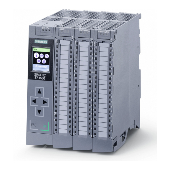
Product overview 2.3 Properties 2.3.1 Properties of the CPU part View of the CPU The figure below shows the CPU part of the CPU 1512C-1 PN. Figure 2-1 CPU 1512C-1 PN Note Protective film Note that a protective film is attached to the display of the CPU when shipped from the factory. - Page 23 Internet) and communication with another machine or automation cell. You can find more information on "PROFINET IO" in the online help of STEP 7 (TIA Portal) and the PROFINET Function Manual (http://support.automation.siemens.com/WW/view/en/68039307). – OPC UA With OPC UA, data is exchanged via an open and vendor-neutral communication protocol.
- Page 24 Product overview 2.3 Properties ● Integrated Web server: A Web server is integrated in the CPU. The Web server enables monitoring and administering of the CPU by authorized users over a network. Evaluations, diagnostics, and modifications are thus possible over long distances. All you need is a web browser. With the Web server, you can read out the following data from the CPU and, in some cases, modify and write back the data to the CPU.
- Page 25 For more information about Motion Control, refer to the section Technology functions. For a detailed description of the use of motion control and its configuration, refer to the S7-1500 Motion Control (http://support.automation.siemens.com/WW/view/en/109739589) function manual. TIA Selection Tool SIZER You can also use the or the to create or configure axes.
- Page 26 ● Additional supported functions: – PROFIenergy For information on "PROFIenergy", refer to the PROFINET (http://support.automation.siemens.com/WW/view/en/68039307) function manual and the PROFINET specification on the Internet (http://www.profibus.com). – Shared Device For information on "Shared Device" refer to the PROFINET (http://support.automation.siemens.com/WW/view/en/68039307) function book.
-
Page 27: Properties Of The Analog On-Board I/O
Product overview 2.3 Properties 2.3.2 Properties of the analog on-board I/O View The following figure shows the analog on-board I/O (X10) of the CPU 1512C-1 PN. Figure 2-2 Analog on-board I/O CPU 1512C-1 PN (6ES7512-1CK00-0AB0) Manual, 09/2016, A5E35306440-AB... - Page 28 Product overview 2.3 Properties Properties The analog on-board I/O has the following technical properties: ● Analog inputs – 5 analog inputs – Resolution 16 bits including sign – Voltage measurement type can be set individually for channel 0 to 3 –...
-
Page 29: Properties Of The Digital On-Board I/O
Product overview 2.3 Properties 2.3.3 Properties of the digital on-board I/O View The following figure shows the digital on-board I/O (X11 and X12) of the CPU 1512C-1 PN. Figure 2-3 Digital on-board I/O CPU 1512C-1 PN (6ES7512-1CK00-0AB0) Manual, 09/2016, A5E35306440-AB... - Page 30 Product overview 2.3 Properties Properties The digital on-board I/O has the following technical properties: ● Digital inputs – 32 high-speed digital inputs for signals up to max. 100 kHz The inputs can be used as standard inputs and as inputs for technology functions. –...
-
Page 31: Operator Controls And Display Elements
Product overview 2.4 Operator controls and display elements Simultaneous use of technology and standard functions You can use technology and standard functions at the same time, provided the hardware allows this. For example, all the digital inputs not assigned to the counting, measuring or position detection or PTO technology functions can be used as standard DI. - Page 32 S7-1500, ET 200MP (http://support.automation.siemens.com/WW/view/en/59191792) system manual. Reference You will find detailed information on the individual display options, a training course and a simulation of the available menu commands in the SIMATIC S7-1500 Display Simulator (http://www.automation.siemens.com/salesmaterial-as/interactive-manuals/getting- started_simatic-s7-1500/disp_tool/start_en.html). CPU 1512C-1 PN (6ES7512-1CK00-0AB0)
-
Page 33: Front View Without Front Panel On The Cpu
Product overview 2.4 Operator controls and display elements 2.4.2 Front view without front panel on the CPU The following figure shows the operator control and connection elements of the CPU 1512C-1 PN with the front cover of the CPU open. ①... -
Page 34: Rear View
Product overview 2.5 Mode selector 2.4.3 Rear view The following figure shows the connection elements on the rear of the CPU 1512C-1 PN. ① Shield contact surfaces ② Plug-in connection for power supply ③ Plug-in connection for backplane bus ④ Fastening screws Figure 2-7 View of the CPU 1512C-1 PN - rear... -
Page 35: Technology Functions
Technology functions High-speed counters Properties The technology functions of the compact CPU have the following technical properties: ● 32 high-speed digital inputs (up to 100 kHz), isolated – 6 high-speed counters (High Speed Counter/HSC), which can all be used as A/B/N ●... -
Page 36: Functions
Technology functions 3.1 High-speed counters 3.1.1 Functions 3.1.1.1 Counting Counting refers to the detection and adding up of events. The counters acquire and evaluate encoder signals and pulses. You can specify the count direction using encoder or pulse signals or through the user program. You can control counting processes using the digital inputs. -
Page 37: Measuring
The hysteresis prevents these unwanted switching operations. Reference For more information on the counter, refer to the S7-1500, ET 200MP, ET 200SP Counting, measurement and position detection function manual (http://support.automation.siemens.com/WW/view/en/59709820). 3.1.1.2 Measuring Measuring functions The following measuring functions are available:... -
Page 38: Position Detection For Motion Control
For a detailed description of the use of motion control and its configuration, refer to the S7-1500 Motion Control function manual (http://support.automation.siemens.com/WW/view/en/59381279). In the function module, the interface between the drives and encoders is referred to as a technology module (TM). In this context, a technology module (TM) also refers to the digital on-board I/O of the compact CPU described here. -
Page 39: Additional Functions
Technology functions 3.1 High-speed counters 3.1.1.4 Additional functions Synchronization You can configure an external reference signal edge to load the counter with the specified start value. The following external signals can trigger a synchronization: ● Rising or falling edge of a digital input ●... -
Page 40: Configuring The High-Speed Counters
> Counting, measuring and position detection (S7-1500)" A detailed description of configuring Motion Control be found in: ● S7-1500 Motion Control (http://support.automation.siemens.com/WW/view/en/59381279) function manual ● in the STEP 7 online help under "Using technology functions > Motion Control > Motion Control (S7-1500)"... - Page 41 Technology functions 3.1 High-speed counters Control interface per channel The following table shows the control interface assignment: Table 3- 3 Assignment of the control interface Offset from start Parameter Meaning address Bytes 0 to 3 Slot 0 Load value (meaning of the value is specified in LD_SLOT_0) Bytes 4 to 7 Slot 1 Load value (meaning of the value is specified in LD_SLOT_1)
-
Page 42: Assignment Of The Feedback Interface Of The High-Speed Counters
For information on configuring the technology object and programming the associated instruction, refer to the S7-1500, ET 200MP, ET 200SP Counting, measurement and position detection (http://support.automation.siemens.com/WW/view/en/59709820) function manual. CPU 1512C-1 PN (6ES7512-1CK00-0AB0) Manual, 09/2016, A5E35306440-AB... - Page 43 Technology functions 3.1 High-speed counters Feedback interface per channel The following table shows the feedback interface assignment: Table 3- 4 Assignment of the feedback interface Offset from start Parameter Meaning address Bytes 0 to 3 COUNT VALUE Current count value Bytes 4 to 7 CAPTURED VALUE Last Capture value acquired...
-
Page 44: Pulse Generators
Technology functions 3.2 Pulse generators Pulse generators 3.2.1 Operating modes 3.2.1.1 Operating mode: Pulse-width modulation (PWM) Properties The pulse-width modulation (PWM) mode of the compact CPU has the following technical properties: Minimum Maximum Standard output High-speed output High-speed out- Standard High-speed High-speed deactivated... - Page 45 Technology functions 3.2 Pulse generators Principle of operation With pulse width modulation, a signal with defined cycle duration and variable on-load factor is output at the digital output. The on-load factor is the relationship of the pulse duration to the cycle duration. In PWM mode, you can control the on-load factor and the cycle duration. With pulse width modulation you vary the mean value of the output voltage.
- Page 46 Technology functions 3.2 Pulse generators Controller For the pulse width modulation (PWM) mode, the user program directly accesses the control and feedback interface of the channel. A reconfiguration via the instructions WRREC/RDREC and parameter assignment data record 128 is supported. You can find additional information in section Parameter data records (PWM) (Page 169) You control the on-load factor (pulse cycle ratio) of the pulse width via the OUTPUT_VALUE...
- Page 47 Technology functions 3.2 Pulse generators Canceling the output sequence A deactivation of the software enable (SW_ENABLE = 1 → 0) cancels the current output sequence. The last cycle duration is not completed. STS_ENABLE and the digital output PWM DQA are immediately reset to 0. A renewed pulse output is only possible after a restart of the output sequence.
- Page 48 Technology functions 3.2 Pulse generators Setting and changing the pulse on-load factor OUTPUT_VALUE assigns the on-load factor for the current period duration. You select the range of the field OUTPUT_VALUE of the control interface with the "Output format" parameter. ● Output format per 100: Value range between 0 and 100 Pulse duration = (OUTPUT_VALUE/100) x period duration.
- Page 49 Technology functions 3.2 Pulse generators Setting the minimum pulse duration and the minimum interpulse period You assign the minimum pulse duration and the minimum interpulse period as DWORD numerical value between 0 and 10 000 000 μs (10 s) with the help of the channel parameter configuration "Minimum pulse duration".
- Page 50 Technology functions 3.2 Pulse generators Category Parameter Meaning Value range Default Per 100 Interprets the ratio value in the field "OUTPUT_VALUE"of the control interface percentage value of the current period duration. Supported value range 0 to 100 Per 1,000 Interprets the ratio value in the field "OUTPUT_VALUE"of the control interface is a one-tenth percentage point of the current period duration.
-
Page 51: Operating Mode: Frequency Output
Technology functions 3.2 Pulse generators Output signals for pulse width modulation (PWM) mode Output signal Meaning Value range Continuous pulse current at the digital A pulse is output at the digital output PWM Continuous pulse current output PWM DQA DQA for the set on-load factor and cycle duration. - Page 52 Technology functions 3.2 Pulse generators Controller For the frequency output mode, the user program directly accesses the control and feedback interface of the channel. A reconfiguration via the instructions WRREC/RDREC and parameter assignment data record 128 is supported. You can find additional information in section Parameter data records (PWM) (Page 169).
- Page 53 Technology functions 3.2 Pulse generators Setting and changing the output value (frequency) You set the frequency with the OUTPUT_VALUE directly with the control program in the control interface. The value is specified in the real format and the unit is always "Hz". The possible range depends on the parameter "High-speed output (0.1 A)"...
- Page 54 Technology functions 3.2 Pulse generators Category Parameter Meaning Value range Default Diagnostics No supply voltage The parameter "No supply voltage Deactivated Deactivated interrupt L+" activates the diagnostic inter- rupt of the channel in the case of Activated no supply voltage L+ Parameter High-speed output The "High-speed output (0.1 A)"...
-
Page 55: Operating Mode: Pto
Technology functions 3.2 Pulse generators 3.2.1.3 Operating mode: PTO The PTO (Pulse Train Output) mode can be used to output position information. This allows you to, for example, control stepper motor drives or simulate an incremental encoder. The frequency of the pulses represents the speed, while the number of pulses represents the distance. - Page 56 Technology functions 3.2 Pulse generators ● PTO (A, B phase-shifted): When you select the PTO signal type (A, B phase-shifted), the two outputs pulses with the specified velocity, but phase-shifted by 90 degrees. This is a 1x combination in which the pulse shows the duration between two positive transitions of A.
- Page 57 Technology functions 3.2 Pulse generators Parameters of PTO mode Category Parameter Meaning Value range Default Diagnostics No supply voltage L+ With the parameter "No sup- Deactivated Deactivated interrupt ply voltage L+" you activate Activated the diagnostic interrupt of the channel in the case of no supply voltage L+.
- Page 58 Technology functions 3.2 Pulse generators Category Parameter Meaning Value range Default Fine resolu- Bits in incr. actual The parameter defines the tion value (G1_XIST1) number of bits for the coding of the fine resolution in the current incremental value of G1_XIST1.
- Page 59 PROFIdrive interface "Telegram 3". For a detailed description of the use of motion control and its configuration, refer to the S7-1500 Motion Control function manual (http://support.automation.siemens.com/WW/view/en/59381279) and the STEP 7 online help. CPU 1512C-1 PN (6ES7512-1CK00-0AB0)
-
Page 60: Functions
Technology functions 3.2 Pulse generators 3.2.2 Functions 3.2.2.1 Function: High-speed output The function "High-speed output (0.1 A)" enhances the signal clock of the digital outputs (DQ0 to DQ7). Less delay, fluctuation, jitter, and shorter rise and fall times, occur at the switching edges. -
Page 61: Function: Direct Control Of The Pulse Output (Dqa)
Technology functions 3.2 Pulse generators 3.2.2.2 Function: Direct control of the pulse output (DQA) Direct control of the pulse output (DQA) In the modes "Pulse width modulation PWM" and "Frequency output", you can set the pulse output (DQA) of a pulse generator directly via the control program. Select the function for the DQ direct control by deleting the output control bit of the PWM channel (TM_CTRL_DQ = 0) in the control interface. -
Page 62: Configuring The Pwm And Frequency Output Modes
Technology functions 3.2 Pulse generators 3.2.3 Configuring the PWM and frequency output modes 3.2.3.1 Assignment of the control interface The user program influences the behavior of the PWM channel through the control interface. Control interface per channel The following table shows the control interface assignment: Table 3- 5 Assignment of the control interface Byte 0... - Page 63 Technology functions 3.2 Pulse generators Control interface parameters OUTPUT_VALUE The interpretation of the value OUTPUT_VALUE depends on the set operating mode. OUTPUT_VALUE is always updated. When an invalid value is detected (outside the permissible range), the error memory bit ERR_OUT_VAL is set until a valid value is detected.
-
Page 64: Handling The Slot Parameter (Control Interface)
Technology functions 3.2 Pulse generators 3.2.3.2 Handling the SLOT parameter (control interface) SLOT and MODE_SLOT SLOT has the following operating modes. ● Mode for individual update (MODE_SLOT = 0) Use this mode if you occasionally change the specific parameters (such as period duration) before the start of the output sequence or during operation. - Page 65 Technology functions 3.2 Pulse generators Interpretation of the SLOT parameter value The value written in the SLOT parameter is displayed as in the table below depending on the LD_SLOT value and the mode is interpreted. LD_SLOT Meaning of SLOT value Valid modes for using the SLOT data type SLOT value...
- Page 66 Technology functions 3.2 Pulse generators Note that the following requirements apply to the representation shown above: ● The value MODE_SLOT must be set to 0 ● Errors or invalid values are shown in the feedback bit ERR_SLOT_VAL ● The error must be acknowledged If MODE_SLOT 0 = 1, the following applies (for PWM mode only): ●...
-
Page 67: Assignment Of The Feedback Interface
Technology functions 3.2 Pulse generators 3.2.3.3 Assignment of the feedback interface The user program receives current values and status information from the pulse width modulation via the feedback interface. Feedback interface per channel The following table shows the feedback interface assignment: Table 3- 6 Assignment of the feedback interface Byte 0... - Page 68 Technology functions 3.2 Pulse generators Feedback parameters Table 3- 7 Status feedback Feedback parameters Meaning Value range STS_READY The channel is correctly configured, is operating and 0: Not ready to run supplying valid data. 1: Ready to run STS_SW_ENABLE Current status of the software enable 0: SW_ENABLE is not active 1: SW_ENABLE detected STS_LD_SLOT...
-
Page 69: Wiring
Wiring Supply voltage 24 V DC supply voltage (X80) The connecting plug for the supply voltage is plugged in when the CPU ships from the factory. The following table shows the terminal assignment for a 24 V DC power supply. ①... -
Page 70: Profinet Interfaces
Reference For more information on "Wiring the CPU" and "Accessories/spare parts", refer to the S7-1500, ET 200MP system manual (http://support.automation.siemens.com/WW/view/en/59191792). Assignment of the MAC addresses The CPU 1512C-1 PN has a PROFINET interface with two ports. The PROFINET interface itself has a MAC address, and each of the two PROFINET ports has its own MAC address. -
Page 71: Terminal And Block Diagrams
Wiring 4.3 Terminal and block diagrams Terminal and block diagrams 4.3.1 Block diagram of the CPU part Block diagram The following figure shows the block diagram of the CPU part. ① Display X80 24 V DC Infeed of supply voltage ②... -
Page 72: Terminal And Block Diagram Of The Analog On-Board I/O
This section contains the block diagram of the analog on-board I/O (X10) and various wiring options. For information on wiring the front connector, establishing the cable shield, etc., refer to the S7-1500, ET 200MP (http://support.automation.siemens.com/WW/view/en/59191792) system manual. Note You can use and combine the different wiring options for all channels. Note, however, that unneeded terminals of an analog input channel must not be connected. - Page 73 Wiring 4.3 Terminal and block diagrams Wiring: Voltage measurement The following figure shows the terminal assignment for voltage measurement at the channels available for this measurement type (channels 0 to 3). ① Analog-to-digital converter (ADC) ② LED interface ③ Infeed element (for shielding only) ④...
- Page 74 Wiring 4.3 Terminal and block diagrams Wiring: 4-wire measuring transducer for current measurement The following figure shows the terminal assignment for current measurement with 4-wire measuring transducer at the channels available for this measurement type (channels 0 to 3). ① Analog-to-digital converter (ADC) ②...
- Page 75 Wiring 4.3 Terminal and block diagrams Wiring: 2-wire measuring transducer for current measurement Alternatively to connecting a 4-wire transducer, you can also connect 2-wire transducers to channels 0 to 3. An external 24 V power supply is required to connect a 2-wire transducer to the analog on-board I/O of the compact CPU.
- Page 76 Wiring 4.3 Terminal and block diagrams Wiring: 4-wire connection of resistance-type sensors or thermal resistors (RTD) The following figure shows the terminal assignment for 4-wire connection of resistance-type sensors or thermal resistors at the channel available for this (channel 4). ①...
- Page 77 Wiring 4.3 Terminal and block diagrams Wiring: 3-wire connection of resistance-type sensors or thermal resistors (RTD) The following figure shows the terminal assignment for 3-wire connection of resistance-type sensors or thermal resistors at the channel available for this (channel 4). Note 3-wire connection Note that line resistances are not compensated with a 3-wire connection.
- Page 78 Wiring 4.3 Terminal and block diagrams Wiring: 2-wire connection of resistance-type sensors or thermal resistors (RTD) The following figure shows the terminal assignment for 2-wire connection of resistance-type sensors or thermal resistors at the channel available for this (channel 4). Note 2-wire connection Note that line resistances are not compensated with a 2-wire connection.
- Page 79 Wiring 4.3 Terminal and block diagrams Wiring: Voltage output The figure below shows the terminal assignment for the wiring of the voltage outputs with: ● 2-wire connection, no compensation for line resistances. ① Analog-to-digital converter (ADC) ② LED interface ③ Infeed element (for shielding only) ④...
- Page 80 Wiring 4.3 Terminal and block diagrams Wiring: Current output The following figure shows an example of the terminal assignment for wiring current outputs. ① Analog-to-digital converter (ADC) ② LED interface ③ Infeed element (for shielding only) ④ Digital-to-analog converter (DAC) ⑤...
-
Page 81: Terminal And Block Diagram Of The Digital On-Board I/O
For information on wiring the front connector, establishing the cable shield, etc., refer to the S7-1500, ET 200MP (http://support.automation.siemens.com/WW/view/en/59191792) system manual. Infeed element The infeed element is inserted on the front connector and serves to shield the digital on- board I/O. - Page 82 Wiring 4.3 Terminal and block diagrams Block diagram and terminal assignment X11 The figure below shows you how to connect the digital on-board I/O X11 and the assignment of the channels to the addresses (input byte a and b, output byte c and d). ①...
- Page 83 Wiring 4.3 Terminal and block diagrams Block diagram and terminal assignment X12 The figure below shows you how to connect the digital on-board I/O X12 and the assignment of the channels to the addresses (input byte a and b, output byte c and d). ①...
- Page 84 Wiring 4.3 Terminal and block diagrams Supply voltage using the digital on-board I/O X11 as an example The inputs and outputs of the digital on-board I/O are divided into two load groups, which are supplied with 24 V DC. The digital inputs DI0 to DI15 form a load group and are supplied via the connections 1L+ (terminal 19) and 1M (terminal 20).
- Page 85 Wiring 4.3 Terminal and block diagrams As a supplement to the block diagram and terminal assignment, the following figure shows the correct wiring of the outputs in order to prevent switching of the outputs in the event of a ground wire break. Figure 4-13 Correct wiring using the digital on-board I/O X11 as an example The ground is supplied with a first cable from the central terminal block to terminal 30 of the...
- Page 86 Wiring 4.3 Terminal and block diagrams The figure below shows the current flow with correct wiring. Figure 4-14 Current flow with correct wiring using the digital on-board I/O X11 as an example With correct wiring, the supply current flows from the power supply 2L+ via terminal 29 to the module.
- Page 87 Wiring 4.3 Terminal and block diagrams The figure below shows the reaction to interruption of the first ground cable. Figure 4-15 Interruption of the first ground cable using the digital on-board I/O X11 as an example If a wire break occurs on the first ground cable from the central terminal block to terminal 30, the module can continue to operate without restrictions, as it is still connected to the ground via the second cable from the central terminal block to terminal 40.
- Page 88 Wiring 4.3 Terminal and block diagrams The figure below shows the reaction to interruption of the second ground cable. Figure 4-16 Interruption of the second ground cable using the digital on-board I/O X11 as an example If a wire break occurs on the second ground cable from the central block terminal to terminal 30, the module can continue to operate without restrictions, as it is still connected to the ground via the first cable from the central terminal block to terminal 40.
- Page 89 Wiring 4.3 Terminal and block diagrams The figure below shows the current flow upon interruption of both ground cables. Figure 4-17 Current flow upon interruption of both ground cables using the digital on-board I/O X11 as an example If a wire break occurs on the first and on the second ground cable from the central terminal block to the terminals 30 and 40 of the module, a malfunction occurs on the module.
- Page 90 Wiring 4.3 Terminal and block diagrams Faulty wiring The following figure shows faulty wiring, which has a bridge on the front connector. Figure 4-18 Faulty wiring using the digital on-board I/O X11 as an example: Bridge Terminals 30 and 40 are connected in the front connector and only routed with one cable to the central terminal block.
- Page 91 Wiring 4.3 Terminal and block diagrams The figure below shows the current flow when the ground connections of the loads and the ground connection of terminal 30 are routed with a common cable to the central terminal block. ① Ground connections of other plant parts that can also carry large currents. Figure 4-19 Faulty wiring using the digital on-board I/O X11 as an example: Common cable If a break occurs in the common cable, the current of the outputs flows via terminal 30 to the...
- Page 92 Wiring 4.3 Terminal and block diagrams The figure below shows the current flow with correct wiring when a potential difference exits between the grounding points. ① Grounding point functional earth 1 (FE 1) ② Grounding point functional earth 2 (FE 2) Figure 4-20 Potential difference using the digital on-board I/O X11 as an example Equipotential bonding occurs via terminals 30 and 40.
-
Page 93: Addresses Of The High-Speed Counters
40-pin front connectors of the digital on-board I/O. For information on wiring the front connectors, establishing the cable shields, etc., refer to the S7-1500, ET 200MP (http://support.automation.siemens.com/WW/view/en/59191792) system manual. CPU 1512C-1 PN (6ES7512-1CK00-0AB0) Manual, 09/2016, A5E35306440-AB... - Page 94 Wiring 4.3 Terminal and block diagrams Encoder signals The 24 V encoder signals are designated with letters A, B and N. You can connect the following encoder types: ● Incremental encoder with signal N: Signals A, B and N are connected using the correspondingly marked connections. Signals A and B are the two incremental signals, phase-shifted by 90°.
- Page 95 Wiring 4.3 Terminal and block diagrams Input addresses of the high-speed counters You set the digital input addresses used by the high-speed counters (HSC) and the assignment of A/B/N, DI0, DI1 and DQ1 signals in STEP 7 (TIA Portal). You can enable and configure each HSC when you configure the compact CPU.
-
Page 96: Addresses Of The Pulse Generators In The Pulse Width Modulation (Pwm) And Frequency Output Modes
Reference For more information on configuring the inputs of the high-speed counters, refer to the S7-1500, ET 200MP, ET 200SP Counting, measurement and position detection (http://support.automation.siemens.com/WW/view/en/59709820) function manual and the STEP 7 online help. 4.3.5 Addresses of the pulse generators in the Pulse Width Modulation (PWM) and... -
Page 97: Addresses Of Pulse Generators In The Pto Mode
40-pin front connectors of the digital on-board I/O. For information on wiring the front connectors and establishing the cable shield, refer to the S7-1500, ET 200MP system manual (http://support.automation.siemens.com/WW/view/en/59191792). Encoder signals In addition to supporting its outputs, each PTO channel also supports the three following optional inputs: ●... -
Page 98: Interconnection Overview Of The Inputs
Wiring 4.3 Terminal and block diagrams 4.3.7 Interconnection overview of the inputs Combined interconnection of the technology channels In order that you can correctly divide the available inputs between the possible technology channels HSC and PTO, the following table provides you with an overview of the possible interconnections of the front connectors X11 and X12. - Page 99 Wiring 4.3 Terminal and block diagrams Front con- Terminal Channel High-speed counter (HSC) nector PTO1 PTO2 PTO3 PTO4 HSC4 HSC5 HSC6 [DR] [DR] [DR] [DR] [DR] [DR] [DR] [DR] [DR] [DR] [DR] [DR] [DR] [DR] [DR] [DR] [DR] [DR] [DR] [DR] [DR] [DR]...
-
Page 100: Interconnection Overview Of Outputs
Wiring 4.3 Terminal and block diagrams 4.3.8 Interconnection overview of outputs Combined interconnection of the technology channels The following table provides you with an overview of the possible interconnections of the front connectors X11 and X12 to allow you to correctly divide the available inputs between the possible technology channels HSC, PWM and PTO. - Page 101 Wiring 4.3 Terminal and block diagrams [PTO 1/2/3/4] [PTO 1/2/3/4] [PTO 1/2/3/4] [PTO 1/2/3/4] [PTO 1/2/3/4] [PTO 1/2/3/4] [PTO 1/2/3/4] [PTO 1/2/3/4] [PTO 1/2/3/4] [PTO 1/2/3/4] Standard DQ10 DQ10 [PTO 1/2/3/4] DQ11 DQ11 [PTO 1/2/3/4] DQ12 DQ12 [PTO 1/2/3/4] DQ13 DQ13 [PTO 1/2/3/4] DQ14...
- Page 102 Wiring 4.3 Terminal and block diagrams Technical characteristics of the outputs The following table shows an overview of the technical characteristics of the individual outputs. Frequency range DQ0 to DQ7 DQ8 to DQ15 (period duration) High-speed output High-Speed output Standard output (0.1 A) activated (0.1 A) deactivated max.
-
Page 103: Parameters/Address Space
Parameters/address space Address space of the analog on-board I/O Address space of the analog input and output channels The addresses are divided into five analog input channels and two analog output channels. STEP 7 (TIA Portal) assigns the addresses automatically. You can change the addresses in the hardware configuration of STEP 7 (TIA Portal), i.e. - Page 104 Parameters/address space 5.1 Address space of the analog on-board I/O Value status (quality information, QI) As of firmware version 2.0, the analog and digital on-board I/O support the value status as diagnostics option. You activate the use of the value status in the hardware configuration of STEP 7 (TIA Portal).
-
Page 105: Address Space Of The Digital On-Board I/O
Parameters/address space 5.2 Address space of the digital on-board I/O Address space of the digital on-board I/O Address space of digital input and digital output channels The addresses are divided into 2 x 16 digital input channels and 2 x 16 digital output channels. - Page 106 Parameters/address space 5.2 Address space of the digital on-board I/O Figure 5-3 Address space of the submodule X12 of the 2 x 32-channel digital on-board I/O (16 digital inputs/16 digital outputs) with value status CPU 1512C-1 PN (6ES7512-1CK00-0AB0) Manual, 09/2016, A5E35306440-AB...
- Page 107 Parameters/address space 5.2 Address space of the digital on-board I/O Value status (quality information, QI) As of firmware version 2.0, the analog and digital on-board I/O support the value status as diagnostics option. You activate the use of the value status in the hardware configuration of STEP 7 (TIA Portal).
-
Page 108: Address Space Of The Pulse Generators
Parameters/address space 5.3 Address space of the pulse generators Address space of the high-speed counters Table 5- 1 Size of the input and output addresses of the high-speed counters Inputs Outputs Size per high-speed counter (6x) 16 bytes 12 bytes You can find a description of the control interface in the section Assignment of the control interface of the high-speed counters (Page 40). -
Page 109: Measurement Types And Measuring Ranges Of The Analog On-Board I/O
Parameters/address space 5.4 Measurement types and measuring ranges of the analog on-board I/O Measurement types and measuring ranges of the analog on-board I/O Introduction The analog on-board I/O is set to voltage measurement type and measuring range ±10 V by default for the inputs on channels 0 to 3. -
Page 110: Output Type And Output Ranges Of The Analog On-Board I/O
Parameters/address space 5.5 Output type and output ranges of the analog on-board I/O Output type and output ranges of the analog on-board I/O Introduction The analog on-board I/O is set to voltage output type and output range ±10 V as default for the outputs. - Page 111 Parameters/address space 5.6 Parameters of the analog on-board I/O Table 5- 6 Configurable "Measuring" parameters Parameters Value range Default Reconfiguration in RUN Measuring See section Measurement Voltage Measurement type • types and measuring ranges (channels 0 to 3) of the analog on-board I/O Resistance (Page 109) (channel 4)
- Page 112 Parameters/address space 5.6 Parameters of the analog on-board I/O Configurable parameters and default settings for outputs Table 5- 8 Configurable "Diagnostics" parameters Parameters Value range Default Reconfiguration in RUN Diagnostics Yes/No Wire break • Yes/No Short-circuit to ground • Yes/No Overflow •...
-
Page 113: Parameters Of The Digital On-Board I/O
Parameters/address space 5.7 Parameters of the digital on-board I/O Parameters of the digital on-board I/O Parameters of the digital on-board I/O in standard mode You specify the properties of the digital on-board I/O during the parameter assignment with STEP 7 (TIA Portal). The tables below list the parameters that can be set for inputs and outputs, respectively. - Page 114 Parameters/address space 5.7 Parameters of the digital on-board I/O Configurable parameters and default settings for outputs Table 5- 11 Configurable parameters for outputs Parameters Value range Default Reconfiguration in RUN Diagnostics Yes/No Missing • supply voltage L+ Reaction to CPU STOP Turn off Turn off •...
-
Page 115: Interrupts/Diagnostics Alarms
Interrupts/diagnostics alarms Status and error displays 6.1.1 Status and error displays of the CPU part LED display The figure below shows the LED displays of the CPU part. ① RUN/STOP LED (yellow/green LED) ② ERROR LED (red LED) ③ MAINT LED (yellow LED) ④... - Page 116 Interrupts/diagnostics alarms 6.1 Status and error displays Meaning of the RUN/STOP, ERROR and MAINT LEDs The CPU has three LEDs for displaying the current operating mode and diagnostics status. The following table shows the meaning of the various combinations of colors for the RUN/STOP, ERROR and MAINT LEDs.
- Page 117 Interrupts/diagnostics alarms 6.1 Status and error displays Meaning of LINK RX/TX LED Each port has a LINK RX/TX LED. The table below shows the various "LED scenarios" of the CPU ports. Table 6- 2 Meaning of the LED LINK TX/RX LED Meaning There is no Ethernet connection between the PROFINET interface of the PROFINET device and the communication partner.
-
Page 118: Status And Error Displays Of The Analog On-Board I/O
Interrupts/diagnostics alarms 6.1 Status and error displays 6.1.2 Status and error displays of the analog on-board I/O LED displays The figure below shows the LED displays (status and error displays) of the analog on-board I/O. Figure 6-2 LED displays CPU 1512C-1 PN (6ES7512-1CK00-0AB0) Manual, 09/2016, A5E35306440-AB... - Page 119 The MAINT-LED is located next the red ERROR-LED on the analog on-board I/O. Note that the MAINT LED on the analog on-board I/O is only intended for troubleshooting by SIEMENS. In normal condition, the MAINT-LED should not light up. However, if the LED is lit up, please contact SIEMENS "mySupport" at Internet (https://support.industry.siemens.com/My/ww/en/).
-
Page 120: Status And Error Displays Of The Digital On-Board I/O
Interrupts/diagnostics alarms 6.1 Status and error displays 6.1.3 Status and error displays of the digital on-board I/O LED displays The figure below shows an example of the LED displays (status and error displays) of the first module of the digital on-board I/O. Corrective measures for diagnostics alarms can be found in the section Interrupts and diagnostics of the digital on-board I/O (Page 125). - Page 121 Interrupts/diagnostics alarms 6.1 Status and error displays Meaning of the LED displays The following tables explain the meaning of the status and error displays. RUN/ERROR LED Table 6- 5 RUN/ERROR status and error displays Meaning Remedy ERROR No voltage or voltage too low Turn on the CPU.
-
Page 122: Interrupts And Diagnostics
Interrupts and diagnostics of the CPU part For information on the topic of "Interrupts", refer to the STEP 7 (TIA Portal) online help. For information on "Diagnostics" and "System alarms", refer to the Diagnostics (http://support.automation.siemens.com/WW/view/en/59192926) function manual. 6.2.2 Interrupts and diagnostics of the analog on-board I/O... - Page 123 Interrupts/diagnostics alarms 6.2 Interrupts and diagnostics Hardware interrupt for inputs The compact CPU can generate a hardware interrupt for the following events: ● Below low limit 1 ● Above high limit 1 ● Below low limit 2 ● Above high limit 2 You can find detailed information on the event in the hardware interrupt organization block with the "RALARM"...
- Page 124 Interrupts/diagnostics alarms 6.2 Interrupts and diagnostics Structure of the additional interrupt information Table 6- 9 Structure of USI = W#16#0001 Data block name Contents Comment Bytes W#16#0001 Additional hardware interrupt information of the (User Structure Identifier) analog on-board I/O The channel that triggered the hardware interrupt follows. Channel B#16#00 to B#16#n Number of the event-triggering channel (n =...
-
Page 125: Interrupts And Diagnostics Of The Digital On-Board I/O
Interrupts/diagnostics alarms 6.2 Interrupts and diagnostics 6.2.3 Interrupts and diagnostics of the digital on-board I/O Diagnostics interrupt A diagnostics alarm is output for each diagnostics event and the ERROR LED flashes on the digital on-board I/O. You can read out the diagnostics alarms, for example, in the diagnostics buffer of the CPU. - Page 126 Interrupts/diagnostics alarms 6.2 Interrupts and diagnostics Hardware interrupt The compact CPU can generate a hardware interrupt for the following events: ● Rising edge ● Falling edge You will find detailed information on the event in the hardware interrupt organization block with the "RALRM"...
- Page 127 Interrupts/diagnostics alarms 6.2 Interrupts and diagnostics Hardware interrupts when using the high-speed counters Table 6- 14 Hardware interrupts and their meaning Hardware interrupt Event type Meaning number Opening of the internal gate (gate When the internal gate is opened, the technology function triggers a start) hardware interrupt in the CPU.
-
Page 128: Technical Specifications
Technical specifications Technical specifications of the CPU 1512C-1 PN 6ES7512-1CK00-0AB0 General information Product type designation CPU 1512C-1 PN Hardware functional status FS03 Firmware version V2.0 Engineering with STEP 7 TIA Portal can be configured/integrated as of version Configuration control Via data record Display Screen diagonal (cm) 3.45 cm... - Page 129 Technical specifications 6ES7512-1CK00-0AB0 24 V encoder supply 24 V Yes; L+ (-0.8 V) Short-circuit protection Output current, max. Power Power consumption from the backplane bus (bal- anced) Power delivered to the backplane bus 10 W Power loss Power loss, typ. 15.2 W Memory SIMATIC memory card required...
- Page 130 Technical specifications 6ES7512-1CK00-0AB0 Number of hardware interrupt OBs Number of DPV1 interrupt OBs Number of isochronous mode OBs Number of technology synchronization interrupt Number of startup OBs Number of asynchronous error OBs Number of synchronous error OBs Number of diagnostics interrupt OBs Nesting depth per priority class Counters, timers and their retentivity...
- Page 131 Technical specifications 6ES7512-1CK00-0AB0 I/O address area Inputs 32 KB; all inputs are within the process image Outputs 32 KB; all outputs are within the process image per integrated IO subsystem 8 KB Inputs (volume) • 8 KB Outputs (volume) • per CM/CP 8 KB Inputs (volume)
- Page 132 Technical specifications 6ES7512-1CK00-0AB0 Digital inputs integrated channels (DI) Configurable digital inputs Sinking/sourcing input Sinking input Input characteristic curve acc. to IEC 61131, type Digital input functions, configurable Gate start/stop Capture Synchronization Input voltage Type of input voltage Rated value (DC) 24 V for signal "0"...
- Page 133 Technical specifications 6ES7512-1CK00-0AB0 Digital output functions, configurable Switch at comparison values Yes; as output signal of a high-speed counter PWM output Number, max. • Configurable cycle duration • On-load factor, min. • 100% On-load factor, max. • 0.0036 %; with S7 analog format, min. 40 ns Resolution of the on-load factor •...
- Page 134 Technical specifications 6ES7512-1CK00-0AB0 Parallel connection of two outputs For logic operations Yes; For technological functions: No For performance increase For redundant activation of a load Yes; For technological functions: No Switching frequency with resistive load, max. 100 kHz; with high-speed output, 10 kHz with standard output with inductive load, max.
- Page 135 Technical specifications 6ES7512-1CK00-0AB0 Input ranges (rated values), currents 0 to 20 mA Yes; physical measuring range: ±20 mA Input resistance (0 to 20 mA) 50 Ω; plus approx. 55 ohm for overvoltage protec- tion by PTC -20 mA to +20 mA Input resistance (-20 mA to +20 mA) 50 Ω;...
- Page 136 Technical specifications 6ES7512-1CK00-0AB0 Cable length shielded, max. 200 m Analog value generation for the inputs Integration and conversion time/resolution per channel Resolution with overrange (bit including sign), 16 bits max. Integration time configurable Yes; 2.5 / 16.67 / 20 / 100 ms, acts on all chan- nels Interference voltage suppression for interference 400 / 60 / 50 / 10...
- Page 137 Technical specifications 6ES7512-1CK00-0AB0 Encoder signals, incremental encoder (asymme- tric) Input voltage 24 V Input frequency, max. 100 kHz Counting frequency, max. 400 kHz; with quadruple evaluation Configurable signal filter Incremental encoder with A/B tracks, 90° phased- shifted Incremental encoder with A/B tracks, 90° phased- shifted and zero track Pulse encoder Pulse encoder with direction...
- Page 138 Technical specifications 6ES7512-1CK00-0AB0 Interference voltage suppression for f = n x (f1 +/- 1%), f1 = interference frequency Series-mode interference (peak of the interference 30 dB < rated value of the input range), min. Common mode voltage, max. 10 V Common mode interference, min.
- Page 139 Technical specifications 6ES7512-1CK00-0AB0 Update time with IRT 250 µs to 4 ms; note: with IRT with isochronous with send clock of 250 µs • mode, the minimum update time of 625 µs of the isochronous OBs is crucial 500 µs to 8 ms; note: with IRT with isochronous with send clock of 500 µs •...
- Page 140 Technical specifications 6ES7512-1CK00-0AB0 Protocols Number of connections Number of connections, max. 128; via integrated interfaces of the CPU and connected CPs/CMs Number of connections reserved for ES/HMI/Web Number of connections via integrated interfaces Number of S7 routing connections PROFINET IO controller Services PG/OP communication •...
- Page 141 Technical specifications 6ES7512-1CK00-0AB0 Open IE communication TCP/IP 64 KB Data length, max. • Multiple passive connections per port, sup- • ported ISO-on-TCP (RFC1006) 64 KB Data length, max. • 1472 bytes Data length, max. • DHCP SNMP LLDP Web server HTTP Yes;...
- Page 142 Technical specifications 6ES7512-1CK00-0AB0 Test - commissioning functions Joint commissioning (team engineering) Yes; parallel online access possible for up to 5 engineering systems Status block Yes; up to 8 simultaneously (in total over all ES clients) Single step Status/modify Status/modify tag Tags Inputs/outputs, bit memory, DB, peripheral in- puts/outputs, timers, counters...
- Page 143 Technical specifications 6ES7512-1CK00-0AB0 Supported technology objects Motion Control Yes; note: the number of axes affects the cycle time of the PLC program; selection guide via the TIA Selection Tool or SIZER Number of available motion control resources • for technology objects (except cams) required Motion Control resources •...
- Page 144 Technical specifications 6ES7512-1CK00-0AB0 Measuring functions Configurable measurement time Dynamic measurement time configuration Number of thresholds, configurable Measuring range 0.04 Hz Frequency measurement, min. • 400 kHz; with quadruple evaluation Frequency measurement, max. • 2.5 μs Period measurement, min. • 25 s Period measurement, max.
- Page 145 Technical specifications 6ES7512-1CK00-0AB0 Configuring Programming Programming language • • • • GRAPH • Know-how protection User program protection Copy protection Block protection Access protection Password for display Protection level: Write protection Protection level: Write/read protection Protection level: Complete protection Cycle time monitoring Low limit Configurable minimum cycle time High limit...
- Page 146 Technical specifications Power reduction (derating) to total current of digital outputs (per power supply) The following figure shows the load rating of the digital outputs in relation to the mounting position and the ambient temperature. ① Horizontal mounting position ② Vertical mounting position Figure 7-1 Loading capacity of the digital outputs per mounting position...
- Page 147 (corresponds to 75% of the digital inputs). General technical specifications For information on the general technical specifications, such as standards and approvals, electromagnetic compatibility, protection class, etc., refer to the S7-1500, ET 200MP system manual (http://support.automation.siemens.com/WW/view/en/59191792). CPU 1512C-1 PN (6ES7512-1CK00-0AB0) Manual, 09/2016, A5E35306440-AB...
-
Page 148: Dimension Drawings
Dimension drawings This appendix contains the dimension drawings of the compact CPU installed on a mounting rail. You must take the dimensions into consideration for installation in cabinets, control rooms, etc. Figure A-1 Dimension drawing of CPU 1512C-1 PN – front and side views CPU 1512C-1 PN (6ES7512-1CK00-0AB0) Manual, 09/2016, A5E35306440-AB... - Page 149 Dimension drawings Figure A-2 Dimension drawing of CPU 1512C-1 PN – side view with front panel open CPU 1512C-1 PN (6ES7512-1CK00-0AB0) Manual, 09/2016, A5E35306440-AB...
-
Page 150: Parameter Data Records
Parameter data records Parameter assignment and structure of the parameter data records of the analog on-board I/O Parameter assignment in the user program You have the option of reassigning parameters for the analog on-board I/O in RUN (for example, measuring ranges of individual channels can be modified in RUN without affecting the other channels). - Page 151 Parameter data records B.2 Structure of a data record for input channels of the analog on-board I/O Data record structure The example in the figure below shows the structure of data record 0 for channel 0. The structure is identical for channels 1 to 4. The values in byte 0 and byte 1 are fixed and must not be changed.
- Page 152 Parameter data records B.2 Structure of a data record for input channels of the analog on-board I/O Figure B-2 Structure of data record 0: Bytes 7 to 27 CPU 1512C-1 PN (6ES7512-1CK00-0AB0) Manual, 09/2016, A5E35306440-AB...
- Page 153 Parameter data records B.2 Structure of a data record for input channels of the analog on-board I/O Codes for measurement types The following table contains all measurement types of the inputs of the analog on-board I/O with the corresponding codes. You must enter these codes in byte 2 of the data record for the corresponding channel (refer to the figure Structure of data record 0: Bytes 0 to 6).
- Page 154 Parameter data records B.2 Structure of a data record for input channels of the analog on-board I/O Codes for temperature coefficient The following table lists all temperature coefficients for temperature measurement of the thermal resistors along with their codes. You must enter these codes in each case in byte 4 of the data record for the corresponding channel (refer to the figure Structure of data record 0: Bytes 0 to 6) Table B- 3...
-
Page 155: Structure Of A Data Record For Output Channels Of The Analog On-Board I/O
Parameter data records B.3 Structure of a data record for output channels of the analog on-board I/O Table B- 6 Limits for thermal resistor Pt 100 Standard and Pt 100 Climate Thermal resistor Pt 100 Standard Pt 100 Climate °C °F °C °F... - Page 156 Parameter data records B.3 Structure of a data record for output channels of the analog on-board I/O Data record structure The figure below shows the structure of data record 64 for channel 0 as an example. The structure is identical for channel 1. The values in byte 0 and byte 1 are fixed and must not be changed.
- Page 157 Parameter data records B.3 Structure of a data record for output channels of the analog on-board I/O Codes for output type The following table contains all output types of the outputs of the analog on-board I/O with the corresponding codes. You must enter these codes in each case in byte 2 of the data record for the corresponding channel (see the previous figure).
-
Page 158: Parameter Assignment And Structure Of The Parameter Data Records Of The Digital On-Board I/O
Parameter data records B.4 Parameter assignment and structure of the parameter data records of the digital on-board I/O Parameter assignment and structure of the parameter data records of the digital on-board I/O Parameter assignment in the user program You have the option of reassigning parameters for the digital on-board I/O in RUN (for example, values for input delay of individual channels can be modified in RUN without affecting the other channels). - Page 159 Parameter data records B.5 Structure of a data record for input channels of the digital on-board I/O Data record structure The example in the figure below shows the structure of data record 0 for channel 0. The structure is identical for channels 1 to 31. The values in byte 0 and byte 1 are fixed and must not be changed.
-
Page 160: Structure Of A Data Record For Output Channels Of The Digital On-Board I/O
Parameter data records B.6 Structure of a data record for output channels of the digital on-board I/O Structure of a data record for output channels of the digital on-board I/O Assignment of data record and channel The parameters per submodule for the 32 digital output channels are located in data records 64 to 79 and are assigned as follows: First submodule (X11): ●... - Page 161 Parameter data records B.6 Structure of a data record for output channels of the digital on-board I/O Data record structure The example in the figure below shows the structure of data record 64 for channel 0. The structure is identical for channels 1 to 31. The values in byte 0 and byte 1 are fixed and must not be changed.
-
Page 162: Parameter Data Records Of The High-Speed Counters
Parameter data records B.7 Parameter data records of the high-speed counters Parameter data records of the high-speed counters You can change the parameters of the High Speed Counter in RUN mode. The WRREC instruction is used to transfer the parameters to the High Speed Counter using data record 128. - Page 163 Parameter data records B.7 Parameter data records of the high-speed counters Table B- 13 Parameter data record 128 - Basic parameters Bit → Byte Basic parameters Reserved = 0 Enable Reaction to CPU STOP: additional : Output substitute diagnostic value interrupts : Keep last value : Continue operation...
- Page 164 Parameter data records B.7 Parameter data records of the high-speed counters Table B- 15 Parameter data record 128 - Hardware interrupts Bit → Byte Hardware interrupts Reserved = Reserved = Reserved = Direction Underflow Overflow Gate stop Gate start reversal (low count- (high count- ing limit...
- Page 165 Parameter data records B.7 Parameter data records of the high-speed counters Bit → Byte Pulse duration (DQ0): WORD: Value range in ms/10: 0 to 65535 Pulse duration (DQ1): WORD: Value range in ms/10: 0 to 65535 Reserved bits must be set to 0 Table B- 17 Parameter data record 128 - Behavior DI0 Bit →...
- Page 166 Parameter data records B.7 Parameter data records of the high-speed counters Table B- 19 Parameter data record 128 - Behavior DI1 Bit → Byte Values 20-23 High counting limit: DWORD: Value range: –2147483648 to 2147483647 or 80000000 to 7FFFFFFF 24-27 Comparison value 0: Counting mode: DWORD Value range: –2147483648 to 2147483647 or 80000000 to 7FFFFFFF...
- Page 167 Parameter data records B.7 Parameter data records of the high-speed counters Table B- 21 Parameter data record 128 - Specify measured value Bit → Byte Specify measured value Reserved = 0 Time base for velocity measurement: Measured variable: : 1 ms : Frequency : 10 ms : Period duration...
- Page 168 Parameter data records B.7 Parameter data records of the high-speed counters Bit → Byte Use of Reserved = 0 Selection HSC DI1 HSC DI1 Value range (applicable if the CPU is configured with deactivated : Not 'Front connector assignment like 1511C' setting): used HSC1..3: : Used...
-
Page 169: Parameter Data Records (Pwm)
Parameter data records B.8 Parameter data records (PWM) Parameter data records (PWM) You have the option of reassigning the pulse width modulation parameters in RUN. The parameters are transferred with the instruction WRREC via the data record 128 to the PWM submodule. - Page 170 Parameter data records B.8 Parameter data records (PWM) Bit → Byte Reserved = 0 Pulse output (DQA) selection Range of values for PWM1: 00000 : Front connector X11, terminal 21 (DQ0) 01000 : Front connector X11, terminal 31 (DQ8) Range of values for PWM2: 00010 : Front connector X11, terminal 23 (DQ2) 01010...
-
Page 171: Analog Value Processing
Analog value processing Conversion method Conversion An integrated analog-to-digital converter converts the analog signal into a digital signal in order that the compact CPU can process the analog signal read in by an analog channel. Once the CPU has processed the digital signal, an integrated digital-to-analog converter converts the output signal into an analog current or voltage value. - Page 172 Analog value processing C.1 Conversion method The following figure shows how this works using a 400 Hz interference frequency suppression as an example. A 400 Hz interference frequency suppression corresponds to an integration time of 2.5 ms. The analog on-board I/O supplies a measured value to the CPU every 1.25 milliseconds within the integration time.
- Page 173 Analog value processing C.1 Conversion method The following figure shows how this works using a 60 Hz interference frequency suppression as an example. A 60 Hz interference frequency suppression corresponds to an integration time of 16.6 ms. The analog on-board I/O supplies a measured value to the CPU every 1.04 milliseconds within the integration time.
- Page 174 Analog value processing C.1 Conversion method The following figure shows how this works using a 50 Hz interference frequency suppression as an example. A 50 Hz interference frequency suppression corresponds to an integration time of 20 ms. The analog on-board I/O supplies a measured value to the CPU every millisecond within the integration time.
- Page 175 • with "Thermal resistor Ni 100 Standard" by ±0.2 K • with "Thermal resistor Ni 100 Climatic" by ±0.1 K A detailed description of the basic and operating error is available in the function manual Analog value processing (http://support.automation.siemens.com/WW/view/en/67989094). CPU 1512C-1 PN (6ES7512-1CK00-0AB0) Manual, 09/2016, A5E35306440-AB...
- Page 176 Analog value processing C.1 Conversion method Smoothing The individual measured values are smoothed by filtering. The smoothing can be set in 4 levels and channel-selective in STEP 7 (TIA Portal). Smoothing time = Smoothing (k) x configured integration time The following figure shows the time it takes for the smoothed analog value to reach approximately 100 % depending on the set smoothing.
- Page 177 The values for the analog input channels are detected sequentially in each cycle. Reference For more information on conversion time, cycle time and conversion method, refer to the Analog value processing (http://support.automation.siemens.com/WW/view/en/67989094) function manual. CPU 1512C-1 PN (6ES7512-1CK00-0AB0) Manual, 09/2016, A5E35306440-AB...
-
Page 178: Representation Of Analog Values
The analog values for all measuring ranges that you can use with the analog on-board I/O are represented in this appendix. For cross-product information on "analog value processing", refer to the Analog value processing (http://support.automation.siemens.com/WW/view/en/67989094) function manual. Measured value resolution Each analog value is entered left aligned into the tags. -
Page 179: Representation Of Input Ranges
Analog value processing C.3 Representation of input ranges Representation of input ranges The tables below set out the digitized representation of the input ranges separately for bipolar and unipolar input ranges. The resolution is 16 bits. Table C- 4 Bipolar input ranges Dec. -
Page 180: Representation Of Analog Values In Voltage Measuring Ranges
Analog value processing C.3 Representation of input ranges C.3.1 Representation of analog values in voltage measuring ranges The following tables list the decimal and hexadecimal values (codes) of the possible voltage measuring ranges. Table C- 6 Voltage measuring ranges ±10 V, ±5 V Values Voltage measuring range Range... -
Page 181: Representation Of Analog Values In Current Measuring Ranges
Analog value processing C.3 Representation of input ranges C.3.2 Representation of analog values in current measuring ranges The following tables list the decimal and hexadecimal values (codes) of the possible current measuring ranges. Table C- 8 Current measuring range ±20 mA Values Current measuring range dec. -
Page 182: Representation Of The Analog Values Of Resistance-Type Sensors/Resistance-Type
Analog value processing C.3 Representation of input ranges C.3.3 Representation of the analog values of resistance-type sensors/resistance-type thermometers The following tables list the decimal and hexadecimal values (codes) of the possible resistance-type sensor ranges. Table C- 10 Resistance-type sensors of 150 Ω, 300 Ω and 600 Ω Values Resistance-type sensor range dec. - Page 183 Analog value processing C.3 Representation of input ranges Table C- 12 Resistance-type thermometer Pt 100 Climate Pt 100 Climate/ Values Pt 100 Climate/ Values Range in °C in °F dec. hex. dec. hex. (1 digit = 0.01 °C) (1 digit = 0.01 °F) >...
-
Page 184: Measured Values For Wire Break Diagnostics
Analog value processing C.3 Representation of input ranges Table C- 14 Resistance-type thermometer Ni 100 Climate Ni 100 Climate in °C Values Ni 100 Climate in Values Range (1 digit = 0.01 °C) °F dec. hex. dec. hex. (1 digit = 0.01 °F) >... -
Page 185: Representation Of Output Ranges
Analog value processing C.4 Representation of output ranges Representation of output ranges The tables below set out the digitalized representation of the output ranges separately for bipolar and unipolar ranges. The resolution is 16 bits. Table C- 16 Bipolar output ranges Dec. -
Page 186: Representation Of Analog Values In The Voltage Output Ranges
Analog value processing C.4 Representation of output ranges C.4.1 Representation of analog values in the voltage output ranges The tables below list the decimal and hexadecimal values (codes) of the possible voltage output ranges. Table C- 18 Voltage output range ±10 V Values Voltage output range Range... -
Page 187: Representation Of Analog Values In The Current Output Ranges
Analog value processing C.4 Representation of output ranges Table C- 20 Voltage output range 1 V to 5 V Values Voltage output range Range dec. hex. 1 to 5 V >117.589% >32511 >7EFF 5.70 V Maximum output value 117.589% 32511 7EFF 5.70 V Overrange... - Page 188 Analog value processing C.4 Representation of output ranges Table C- 22 Current output range 0 to 20 mA Values Current output range Range dec. hex. 0 to 20 mA >117.589% >32511 >7EFF 23.52 mA Maximum output value 117.589% 32511 7EFF 23.52 mA Overrange 27649...
Need help?
Do you have a question about the Simatic S7-1500 and is the answer not in the manual?
Questions and answers