Siemens simatic S7-1500 Manual
Digital outpoot module
Hide thumbs
Also See for simatic S7-1500:
- User manual ,
- System manual (523 pages) ,
- Function manual (402 pages)
Table of Contents
Advertisement
Quick Links
Advertisement
Table of Contents

Related Manuals for Siemens simatic S7-1500


Summary of Contents for Siemens simatic S7-1500
- Page 2 ___________________ Preface ___________________ Documentation guide ___________________ SIMATIC Product overview ___________________ Wiring S7-1500/ET 200MP Digital output module ___________________ DQ 32x24VDC/0.5A HF Parameters/address space (6ES7522-1BL01-0AB0) ___________________ Interrupts/diagnostics alarms Manual ___________________ Technical specifications ___________________ Dimensional drawing ___________________ Parameter data records 09/2016 A5E35683508-AB...
- Page 3 Note the following: WARNING Siemens products may only be used for the applications described in the catalog and in the relevant technical documentation. If products and components from other manufacturers are used, these must be recommended or approved by Siemens. Proper transport, storage, installation, assembly, commissioning, operation and maintenance are required to ensure that the products operate safely and without any problems.
-
Page 4: Preface
Purpose of the documentation This manual supplements the system manual S7-1500/ET 200MP (https://support.industry.siemens.com/cs/ww/en/view/59191792). Functions that relate in general to the systems are described in this system manual. The information provided in this manual and in the system/function manuals supports you in commissioning the systems. - Page 5 In order to protect plants, systems, machines and networks against cyber threats, it is necessary to implement – and continuously maintain – a holistic, state-of-the-art industrial security concept. Siemens’ products and solutions only form one element of such a concept. Customer is responsible to prevent unauthorized access to its plants, systems, machines and networks.
-
Page 6: Table Of Contents
Table of contents Preface ..............................4 Documentation guide ..........................7 Product overview ..........................11 Properties ..........................11 Wiring ..............................13 Parameters/address space ........................16 Parameters ..........................16 Description of parameters ...................... 18 Address space ........................19 Interrupts/diagnostics alarms......................... 25 Status and error displays ....................... 25 Interrupts .......................... -
Page 7: Documentation Guide
Documentation guide The documentation for the SIMATIC S7-1500 automation system, the CPU 1516pro-2 PN based on SIMATIC S7-1500 and the SIMATIC ET 200MP distributed I/O system is arranged into three areas. This arrangement enables you to access the specific content you require. - Page 8 You can download the product information free of charge from the Internet (https://support.industry.siemens.com/cs/us/en/view/68052815). Manual Collection S7-1500/ET 200MP The Manual Collection contains the complete documentation on the SIMATIC S7-1500 automation system and the ET 200MP distributed I/O system gathered together in one file. You can find the Manual Collection on the Internet (https://support.industry.siemens.com/cs/ww/en/view/86140384).
- Page 9 ● Manuals, characteristics, operating manuals, certificates ● Product master data You can find "mySupport" - CAx data on the Internet (http://support.industry.siemens.com/my/ww/en/CAxOnline). Application examples The application examples support you with various tools and examples for solving your automation tasks. Solutions are shown in interplay with multiple components in the system - separated from the focus on individual products.
- Page 10 You can find the SIMATIC Automation Tool on the Internet (https://support.industry.siemens.com/cs/ww/en/view/98161300). PRONETA With SIEMENS PRONETA (PROFINET network analysis), you analyze the PROFINET network during commissioning. PRONETA features two core functions: ● The topology overview independently scans PROFINET and all connected components.
-
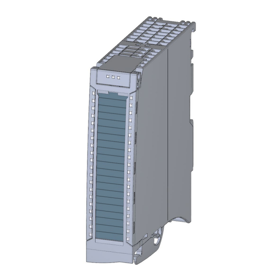
Page 11: Product Overview
Product overview Properties Article number 6ES7522-1BL01-0AB0 View of the module Figure 2-1 View of the DQ 32x24VDC/0.5A HF module Digital output module DQ 32x24VDC/0.5A HF (6ES7522-1BL01-0AB0) Manual, 09/2016, A5E35683508-AB... - Page 12 Other components The following component must be ordered separately: Front connectors, including potential jumpers and cable ties You can find additional information on accessories in the system manual S7-1500/ET 200MP (https://support.industry.siemens.com/cs/ww/en/view/59191792). Digital output module DQ 32x24VDC/0.5A HF (6ES7522-1BL01-0AB0) Manual, 09/2016, A5E35683508-AB...
-
Page 13: Wiring
This section contains the block diagram of the module and outlines various wiring options. You can find information on wiring the front connector, establishing a cable shield, etc. in the system manual S7-1500/ET 200MP (https://support.industry.siemens.com/cs/ww/en/view/59191792). Digital output module DQ 32x24VDC/0.5A HF (6ES7522-1BL01-0AB0) Manual, 09/2016, A5E35683508-AB... - Page 14 Wiring Wiring and block diagram The example in the following figure shows the terminal assignment and the assignment of the channels to the addresses (output byte a to output byte d). ① Backplane bus interface Channel or channel status LED (green/red) Supply voltage 24 V DC Status display LED (green) Ground...
- Page 15 Wiring Tip: Using the potential jumpers Use the potential jumpers supplied with the front connector if you want to connect the four load groups to the same potential (non-isolated). This helps you to avoid having to terminate two wires to one terminal. Proceed as follows: 1.
-
Page 16: Parameters/Address Space
Parameters/address space Parameters DQ 32x24VDC/0.5A HF parameters When you assign the module parameters in STEP 7, you use various parameters to specify the module properties. The following table lists the configurable parameters. The effective range of the configurable parameters depends on the type of configuration. The following configurations are possible: ●... - Page 17 Parameters/address space 4.1 Parameters For parameter assignment in the user program, the parameters are transferred to the module using the WRREC instruction (parameter assignment in RUN) and data records; see chapter Parameter assignment and structure of the parameter data records (Page 35). Table 4- 1 Configurable parameters and their defaults Parameters...
-
Page 18: Description Of Parameters
Parameters/address space 4.2 Description of parameters Description of parameters No supply voltage Enabling of the diagnostics, for lacking or insufficient supply voltage L+. Short circuit to ground Enabling of the diagnostics if a short-circuit of the actuator supply (CHx) to ground occurs. Wire break Enabling of the diagnostics if the line to the actuator is broken. -
Page 19: Address Space
Parameters/address space 4.3 Address space Address space The module can be configured differently in STEP 7; see following table. Depending on the configuration, additional/different addresses are assigned in the process image of the outputs/inputs. Configuration options of DQ 32x24VDC/0.5A HF You can configure the module with STEP 7 (TIA Portal) or with a GSD file. - Page 20 Parameters/address space 4.3 Address space Value status (Quality Information, QI) The value status is always activated for the following module names: ● DQ 32x24VDC/0.5A HF QI ● DQ 32x24VDC/0.5A HF S QI ● DQ 32x24VDC/0.5A HF MSO An additional bit is assigned to each channel for the value status. The bit for the value status indicates if the output value specified by the user program is actually pending at the module terminal (0 = value is incorrect).
- Page 21 Parameters/address space 4.3 Address space Address space for configuration as 4 x 8-channel DQ 32x24VDC/0.5A HF S QI For the configuration as a 4 x 8-channel module, the channels of the module are divided into multiple submodules. The submodules can be assigned to different IO controllers when the module is used in a shared device.
- Page 22 Parameters/address space 4.3 Address space Value status (Quality Information, QI) The meaning of the value status depends on the submodule on which it occurs. For the first submodule (=basic submodule), the value status 0 indicates that the value is incorrect or that the IO controller of the basic submodule is in STOP state. For 2nd to 4th submodule (=MSO submodule), the value status 0 indicates that the value is incorrect or one of the following errors has occurred: ●...
- Page 23 Parameters/address space 4.3 Address space The following figure shows the assignment of the address space for submodules 1 and 2 and the value status. Figure 4-3 Address space for configuration as 1 x 32-channel DQ 32x24VDC/0.5A HF S MSO with value status Digital output module DQ 32x24VDC/0.5A HF (6ES7522-1BL01-0AB0) Manual, 09/2016, A5E35683508-AB...
- Page 24 Reference You can find information on the Shared Input/Output (MSI/MSO) function in the section Module-Internal Shared Input/Output (MSI/MSO) of the PROFINET with STEP 7 V13 (https://support.industry.siemens.com/cs/ww/en/view/49948856) function manual. Digital output module DQ 32x24VDC/0.5A HF (6ES7522-1BL01-0AB0) Manual, 09/2016, A5E35683508-AB...
-
Page 25: Interrupts/Diagnostics Alarms
Interrupts/diagnostics alarms Status and error displays LED displays The following figure shows the LED displays (status and error displays) of module. Figure 5-1 LED displays of the module DQ 32x24VDC/0.5A HF Digital output module DQ 32x24VDC/0.5A HF (6ES7522-1BL01-0AB0) Manual, 09/2016, A5E35683508-AB... - Page 26 Interrupts/diagnostics alarms 5.1 Status and error displays Meaning of the LED displays The tables below explain the meaning of the status and error displays. Remedial measures for diagnostic reports can be found in chapter Diagnostics alarms (Page 28). RUN and ERROR LED Table 5- 1 Status and error displays RUN and ERROR Meaning...
-
Page 27: Interrupts
Interrupts/diagnostics alarms 5.2 Interrupts Interrupts Digital output module DQ 32x24VDC/0.5A HF supports diagnostic interrupts. For detailed information on the error event, refer to the diagnostic interrupt organization block with the "RALRM" instruction (read additional interrupt information) and to the STEP 7 online help. -
Page 28: Diagnostics Alarms
Interrupts/diagnostics alarms 5.3 Diagnostics alarms Diagnostics alarms Diagnostics alarms A diagnostics alarm is generated and the ERROR LED flashes for each diagnostics event on the module. You can read the diagnostics alarms, for example, in the diagnostics buffer of the CPU. You can evaluate the error codes with the user program. If the module is operated distributed with PROFIBUS DP in an ET 200MP system, you have the option to read out diagnostics data with the instruction RDREC or RD_REC using data record 0 and 1. -
Page 29: Technical Specifications
Technical specifications Technical specifications of the DQ 32x24VDC/0.5 A HF 6ES7522-1BL01-0AB0 General information Product type designation DQ 32x24VDC/0,5A HF Hardware functional status FS01 Firmware version V1.0.0 Product function I&M data Yes; I&M0 to I&M3 Engineering with STEP 7 TIA Portal can be configured/integrated V13 SP1 / - as of version PROFIBUS as of GSD version/GSD revision... - Page 30 Technical specifications 6ES7522-1BL01-0AB0 Digital outputs Number of outputs Sourcing output Short-circuit protection Yes; electronic clocking Response threshold, typ. • Limitation of inductive shutdown voltage to L+ (-53 V) Control of a digital input Switching capacity of outputs With resistive load, max. 0.5 A With lamp load, max.
- Page 31 Technical specifications 6ES7522-1BL01-0AB0 Interrupts/diagnostics/status information Diagnostics function Substitute values can be applied Interrupts Diagnostic interrupt Diagnostics alarms Monitoring of supply voltage Wire break Short-circuit Group error Diagnostics indicator LED RUN LED Yes; green LED ERROR LED Yes; red LED Monitoring of supply voltage (PWR LED) Yes;...
- Page 32 Technical specifications Residual current at signal state "0": Note Due to the Diagnostics: Wire break function, there is a low level of residual current in the "0" signal state at the output, which may cause the display diodes to flicker. This residual current does not depend on the setting for the wire break diagnostics parameter.
-
Page 33: Dimensional Drawing
Dimensional drawing Dimensional drawing The dimensional drawing of the module on the mounting rail, as well as a dimensional drawing with open front cover, are provided in this appendix. Always observe the specified dimensions for installations in cabinets, control rooms, etc. Figure A-1 Dimension drawing of the DQ 32x24VDC/0.5A HF module Digital output module DQ 32x24VDC/0.5A HF (6ES7522-1BL01-0AB0) - Page 34 Dimensional drawing A.1 Dimensional drawing Figure A-2 Dimension drawing of the DQ 32x24VDC/0.5A HF module, side view with open front cover Digital output module DQ 32x24VDC/0.5A HF (6ES7522-1BL01-0AB0) Manual, 09/2016, A5E35683508-AB...
-
Page 35: Parameter Data Records
Parameter data records Parameter assignment and structure of the parameter data records The data records of the module have an identical structure, regardless of whether you configure the module with PROFIBUS DP or PROFINET IO. Dependencies for configuration with GSD file When a GSD file is used to configure a module, dependencies can arise when "assigning the parameters". - Page 36 Parameter data records B.1 Parameter assignment and structure of the parameter data records Assignment of data record and channel For the configuration as a 1 x 32-channel module, the parameters are located in data records 64 to 95 and are assigned as follows: ●...
- Page 37 Parameter data records B.1 Parameter assignment and structure of the parameter data records Data record structure The example in the following figure shows the structure of data record 64 for channel 0. The structure of channels 1 to 31 is identical. The values in byte 0 and byte 1 are fixed and may not be changed.
Need help?
Do you have a question about the simatic S7-1500 and is the answer not in the manual?
Questions and answers