
Related Manuals for Mitsubishi Electric FR-PU07


Summary of Contents for Mitsubishi Electric FR-PU07
- Page 1 INVERTER Option unit FR-PU07 INSTRUCTION MANUAL Parameter unit PRE-OPERATION INSTRUCTIONS FUNCTIONS FUNCTION MENU OPERATION SPECIFICATIONS...
- Page 2 REVISIONS Version Art.no. Changes / Additions / Corrections January 2008 209064 —...
-
Page 3: Safety Instructions
Thank you for choosing the Mitsubishi inverter option unit. This instruction manual gives handling information and precautions for use of this equipment. Incorrect handling might cause an unexpected fault. Before using the equipment, please read this manual carefully to use the equipment to its optimum. Please forward this manual to the end user. - Page 4 To prevent injury, damage or product failure, please note the following points: Transportation and mounting CAUTION Do not install and operate the parameter unit (FR-PU07) if it is damaged or has parts missing. Do not stand or rest heavy objects on this equipment. Check the inverter mounting orientation is correct.
- Page 5 When parameter clear or all parameter clear is performed, each parameter returns to the factory setting. Re-set the required parameters before starting operation. Corrective actions for alarm CAUTION Provide safety backup devices, such as an emergency brake, to protect machines and equipment from hazard if the parameter unit (FR-PU07) becomes faulty. Disposal CAUTION Treat as industrial waste.
-
Page 7: Table Of Contents
— Contents — PRE-OPERATION INSTRUCTIONS 1.1 Overview ............. . . 3 1.1.1 Appearance and parts identification . - Page 8 2.2 Frequency Setting ............18 2.2.1 Direct setting .
- Page 9 FUNCTION MENU 3.1 Overview of Function Menu ..........41 3.1.1 Function menu .
- Page 10 OPERATION 4.1 How to Select the Operation Mode ......... . 71 4.1.1 Switching from external operation mode [EXT] to PU operation mode [PU] .
- Page 11 Although this product can be connected to the inverter for the FR-PU04(V), the following differences should be noted: When parameter is read using the FR-PU07, some parameter names are displayed in different names from actual parameters. The FR-PU07 can not be directly connected to the inverter.
-
Page 13: Pre-Operation Instructions
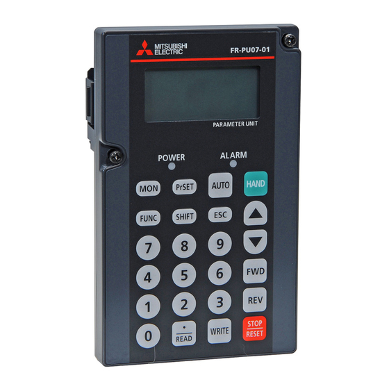
PRE-OPERATION INSTRUCTIONS Overview 1.1.1 Appearance and parts identification Unpack the parameter unit, check the name plate on the back, and make sure that the product has not been damaged before using the equipment. Rear Front POWER lamp Connection connector Lit when the power turns on. Connector to be connected to the inverter. -
Page 14: Explanation Of Keys
PRE-OPERATION INSTRUCTIONS 1.1.2 Explanation of keys Description Used to select the parameter setting mode. Press to select the parameter setting mode. Used to display the first priority screen. Used to display the output frequency when making an initial setting. Operation cancel key. Used to display the function menu. - Page 15 PRE-OPERATION INSTRUCTIONS Description Forward rotation command key. Reverse rotation command key. Stop command key. Used to reset the inverter when an alarm occurs. Used to write a set value in the setting mode. Used as a clear key in the all parameter clear or alarm history clear mode. Used as a decimal point when entering numerical value.
-
Page 16: Installation
PRE-OPERATION INSTRUCTIONS Installation CAUTION To ensure safety, install the FR-PU07 after switching the power of the inverter off. 1.2.1 Direct installation to the inverter Remove the operation panel (FR-DU07). Insert the parameter unit straight and fit it securely. Tighten the two screws on the parameter unit to fix the unit to the inverter. -
Page 17: Installation Using The Connection Cable
1.2.2 Installation using the connection cable Remove the operation panel (FR-DU07). Securely insert one end of connection cable into the PU connector of the inverter and the other end into the connection connector of FR-PU07 along the guides until the stoppers are fixed. Stopper FR-PU07 CAUTION Install the operation panel only when the front cover is installed. -
Page 18: Removal
To ensure safety, remove the FR-PU07 after switching the power of the inverter off. 1.3.1 Removal from the inverter Loosen the fixed screws, hold down the right and left hooks of the FR-PU07, and then pull the parameter unit toward you. Press the hooks Fixed screw 1.3.2 Removal when the connection cable FR-A5 CBL is used... -
Page 19: Parameters To Be Checked First
PRE-OPERATION INSTRUCTIONS Parameters to be Checked First Change the following parameter settings as required. For the changing procedures, refer to page 21. 1.4.1 PU display language selection (Pr. 145) By setting the Pr. 145 "PU display language selection" value, you can select the language displayed on the parameter unit. Setting Display Language Japanese... -
Page 20: Pu Contrast Adjustment (Pr. 991)
PRE-OPERATION INSTRUCTIONS 1.4.3 PU contrast adjustment (Pr. 991) By setting the Pr. 991 "PU contrast adjustment value", you can adjust the contrast for the display panel of the parameter unit. Press the WRITE-key to store the setting value. Setting Description 0 to 63 Light Initial value Dark... -
Page 21: Functions
FUNCTIONS Monitoring Function 2.1.1 Display overview List READ: 120.00 Main monitor Rotation direction indication Operating status indication Main monitor Rotation direction indication Shows the output frequency, output current, output voltage, alarm his- Display the direction (forward rotation/reverserotation) of the start com- tory and other monitor data. - Page 22 FUNCTIONS List READ: 120.00 Warning indication Unit indication Operating mode indication Operation mode indication Warning indication Displays the status of the operation mode. Displays an inverter fault as an alarm. The warning type varies with the EXT: External operation mode inverter model.
-
Page 23: Using The Shift-Key To Change The Main Monitor
FUNCTIONS 2.1.2 Using the SHIFT-key to change the main monitor When "0" (initial value) is set in the Pr. 52 "DU/PU main display data selection", merely pressing the SHIFT-key calls 6 different monitor screens in sequence. Switch power on or press MON-key When output frequency is the When output voltage is the... -
Page 24: Setting The Power-On Monitor (The First Priority Monitor)
FUNCTIONS 2.1.3 Setting the power-on monitor (the first priority monitor) Set the monitor which appears first when power is switched on or MON-key is pressed. When you press the WRITE-key with any monitor screen other than ALARM HISTORY, I/P Signal, O/P Signal, multiple simulta- neous monitor (3-step monitor) being displayed, that screen is set as the power-on screen and will be displayed first. -
Page 25: Using The Read-Key To Change The Main Monitor
FUNCTIONS 2.1.4 Using the READ-key to change the main monitor Press the READ-key to display the monitoring list while the main monitor is displayed. Select a monitor from the monitoring list to change the main monitor. Example: Select the output current peak value monitor. The selective monitor screen is not yet the first priority monitor only when the READ-key was pressed. -
Page 26: Using The Parameter To Change The Monitor (Pr. 52)
FUNCTIONS 2.1.5 Using the parameter to change the monitor (Pr. 52) By setting the Pr. 52 "DU/PU main display data selection", you can change the "Output current monitor" and "Output voltage mon- itor" monitor displays from the first priority monitor using the SHIFT-key. Pr. - Page 27 FUNCTIONS Factory setting The monitor displayed at powering on is the first priority monitor. Refer to page 14 for the setting method of the first priority monitor. First priority monitor Third monitor Second monitor READ: List READ: List READ: List 0.00 120.00 0.00...
-
Page 28: Frequency Setting
FUNCTIONS Frequency Setting The frequency in PU operation mode and external/PU combined operation mode (Pr. 79 = "3") can be set. REMARKS When changing the operation mode from external operation mode to PU operation mode, operation mode can not be changed if the external starting signal (STF or STR) is on. -
Page 29: Step Setting
FUNCTIONS 2.2.2 Step setting A frequency is continuously varied using the Cursor-keys ▲/▼. You can vary the frequency only while you press the ▲/▼-keys. Since the frequency varies slowly at first, this setting can be used for fine adjustment. Example: Changing from 0 Hz setting to 50 Hz setting REMARKS Description Display... -
Page 30: Precautions For Frequency Setting
FUNCTIONS 2.2.3 Precautions for frequency setting Pr. 79 "Operation mode selection" must have been set to switch to the PU operation. (Refer to the inverter instruction manual for details of Pr. 79.) In the monitor mode, you cannot make the direct setting (refer to page 18) to set the running frequency. Perform the step setting (refer to page 18) and press the WRITE-key or press the PU-key to display the frequency setting screen before frequency setting. -
Page 31: Setting And Changing The Parameter Values
FUNCTIONS Setting and Changing the Parameter Values Using the FR-PU07 allows you to read the parameter of inverter or change the set value easily. Refer to the inverter instruction manual for details of the parameters. 2.3.1 Specifying the parameter number to change the set value Example: When changing 5 s to 180 s as the Pr. -
Page 32: Selecting The Parameter From Functional List To Change The Set Value
FUNCTIONS 2.3.2 Selecting the parameter from functional list to change the set value Example: When changing 5 s to 180 s as the Pr. 8 "Deceleration Description Display time setting" ‘ Accl/Decl T Description Display Press the READ-key. 2 Accl/Decl P A function list regarding acceleration/ 3 Brake Seq deceleration is displayed. - Page 33 FUNCTIONS Description Display Direct setting: Press "180". 8 Dec.T1 Enter the desired value. 5.0s ‘ 180s Step setting 0~3600s Press the Cursor-keys ▲/▼. Display "180" using the Cursor-keys ▲/▼. 8 Dec.T1 180.0s Press the WRITE-key. ‘ The set value is changed. Completed Press the SHIFT-key to display the next parameter.
-
Page 34: Selecting The Parameter From Parameter List To Change The Set Value
FUNCTIONS 2.3.3 Selecting the parameter from parameter list to change the set value Example: When changing 5 s to 180 s as the Pr. 8 "Deceleration Description Display time setting" Select the parameter. 8 Dec.T1 Description Display When moving the cursor using the Cur- 5.0s sor-keys ▲/▼... -
Page 35: Selecting The Parameter From User-Set To Change The Set Value
FUNCTIONS 2.3.4 Selecting the parameter from user-set to change the set value If a parameter is registered to user-set, the parameter can be read from user-set list and changed. (For registering the user group, refer to page 26). Example: When changing 5 s to 180 s as the Pr. 8 "Deceleration Description Display time setting"... -
Page 36: User Group Function
FUNCTIONS User Group Function User group function is a function to display only parameters necessary for setting. Among all parameters, max. 16 parameters can be registered to the user group. When "1" is set in Pr. 160, only parameters registered in the user group can be accessed for reading and writing. (The parameters not registered to the user group cannot be read.) -
Page 37: Registering The Parameters To User Group
FUNCTIONS 2.4.1 Registering the parameters to user group Description Display Description Display Register.When moving the cursor to "YES" and pressing the WRITE-key, the registration is executed. SETTING MODE Press the PrSET-key. 0~9:Ser Pr.NO. The parameter unit is put in the param- SETTING MODE eter setting mode. -
Page 38: Deleting The Parameters From User Group
FUNCTIONS 2.4.2 Deleting the parameters from user 2.4.3 Confirming the parameters registered group to user group Description Display Description Display SETTING MODE SETTING MODE Press the PrSET-key. Press the PrSET-key. 0~9:Ser Pr.NO. 0~9:Ser Pr.NO. The parameter unit is put in the param- The parameter unit is put in the param- eter setting mode. -
Page 39: Precautions For Setting Write
FUNCTIONS 2.4.4 Precautions for setting write Perform parameter setting change during an inverter stop basically in the PU operation mode or combined operation mode. The parameter setting can not be changed in the external operation mode or during inverter operation. (Read is performed inde- pendently of the operation mode.) Note that some parameters can be written even in the external operation mode or during operation. -
Page 40: Calibration Of The Meter (Frequency Meter)
FUNCTIONS Calibration of the Meter (Frequency Meter) CAUTION The functions vary with the inverter. (Refer to the inverter instruction manual for details of the parameters.) 2.5.1 Calibration of the FM terminal Description Display 900 FM Tune Run Inverter Parameter Enter "900" and press the READ-key. ‘... -
Page 41: Calibration Of The Am Terminal
FUNCTIONS 2.5.2 Calibration of the AM terminal Description Display Using the Cursor-keys ▲/▼, adjust the Parameter meter pointer to a predetermined posi- Pr. 901 "AM terminal calibration" tion. Pr. 158 "AM terminal function selection" The meter pointer moves. (It takes a long time before the pointer moves.) Pr. - Page 42 FUNCTIONS When calibrating output current Description Display To output the output current or another item which cannot easily 901 AM Tune achieve a 100% value if operation is performed, adjust the ref- Enter "50" and press the WRITE-key. Run Inverter erence voltage output, then select any of the choices displayed.
- Page 43 FUNCTIONS Description Display Description Display 901 AM Tune SETTING MODE Press the PrSET-key. Enter "901" and press the READ-key. Run Inverter 0~9:Ser Pr.NO. The parameter unit is put in the param- ‘ 0.00Hz The current Pr. 901 setting appears. eter setting mode. Select Oper 901 AM Tune 158 AM Set...
-
Page 44: Adjustment Of The Frequency Setting Signals "Bias" And "Gain
FUNCTIONS Adjustment of the Frequency Setting Signals "Bias" and "Gain" CAUTION The functions vary with the inverter model. (Refer to the inverter instruction manual for details of the functions.) 2.6.1 Adjustment procedure There are three ways to adjust the bias and gain of the frequency setting voltage (current): Adjust only the bias and gain frequencies and not adjust the voltage (current) (Refer to page 34) Adjust any point by applying a voltage across terminals 2-5 (starting a current across terminals 4-5)(Refer to page 36) Adjust any point without a voltage being applied across terminals 2-5 (without a current being started across terminals 4-5) - Page 45 FUNCTIONS Description Display Description Display Press the WRITE-key. 902 Ext2bias The bias frequency is set at 10 Hz. Enter "10". ‘ 10Hz At this time, set the gain on the as- Voltage need not be applied across ter- Set<WRITE> sumption that the 5 V (10 V) in the in- minals 2-5.
- Page 46 FUNCTIONS Adjust any point by application of voltage to across Description Display terminals 2-5a Enter "10". Set the bias frequency at 10 Hz. Setting of the frequency setting voltage bias 902 Ext2bias Description Display ‘ 10.00Hz 0.5% Freq Set -10.0% Press the PU-key.
- Page 47 FUNCTIONS Setting of the frequency setting voltage gain Description Display Description Display Press the WRITE-key. The gain frequency is set at 50 Hz for 903 Ext2gain 5 V input. Setting is completed as 903 Ext2gain ‘ 60.00Hz shown below: 50.00Hz Press the SHIFT-key, then the READ- 97.1% 99.6%...
- Page 48 FUNCTIONS Adjust any point without application of voltage to Description Display across terminals 2-5 902 Ext2bias Setting of the frequency setting voltage bias ‘ Enter "10". 10.00Hz Description Display -0.5% Set the bias frequency at 10 Hz. -0.5% Freq Set Press the PU-key.
- Page 49 FUNCTIONS Setting of the frequency setting voltage gain Description Display Description Display Press the WRITE-key. The gain frequency is set at 50 Hz. 903 Ext2gain Setting is completed as shown below: ‘ 60.00Hz Press the SHIFT-key, then the READ- 97.1% 903 Ext2gain key.
- Page 50 FUNCTIONS...
-
Page 51: Function Menu
FUNCTION MENU Overview of Function Menu Press the FUNC-key in any operation mode to call the function menu, on which you can perform various functions. Hold down the SHIFT-key and press ▼ the cursor-key to shift one screen. Menu screen page 1 Menu screen page 2 Menu screen page 3 ‘... - Page 52 FUNCTION MENU Help Menu Description Refer To 4. Pr.Clear The parameter clear menu appears, and you can perform "parameter clear" and "all clear". page 53 5. Alarm Hist This function displays history of past eight faults (alarms). page 55 6. AlarmClear This function clears all the fault (alarm) history.
-
Page 53: Function Menu Transition
FUNCTION MENU 3.1.2 Function menu transition Frequency [Hz] Current [A] Voltage [V] Error description * The latest 8 errors are displayed Frequency setting (shows the frequency already set)[Hz] Running speed (shows the motor speed or moving speed)[r] Motor torque (torque produced by the motor) [%] Converter output voltage(DC voltage in converter output) [V] Regenerative brake duty [%] Electronic thermal relay function load factor [%]... - Page 54 FUNCTION MENU * The latest 8 errors are displayed.
- Page 55 FUNCTION MENU...
- Page 56 FUNCTION MENU Settings of Pr. 178 to Pr. 196 are displayed. Terminal Name...
-
Page 57: Operation Procedures For Functions
FUNCTION MENU Operation Procedures for Functions 3.2.1 Monitor function The monitoring list appears and you can change from one monitor screen to another and set the first priority screen. Description Display Description Display Press the FUNC-key. Press the READ-key. READ: List The function menu is called. -
Page 58: Selection Of Pu Operation (Direct Input)
FUNCTION MENU 3.2.2 Selection of PU operation (direct input) You can select the PU operation mode to set PU operation frequency. Description Display Description Display ‘ READ: MONITOR List Press the FWD- or REV-key to perform 50.00 2 PU Oper Press the FUNC-key forward or reverse rotation with the set 3 Pr.List... -
Page 59: Selection Of The Pu Jog Operation Mode
FUNCTION MENU 3.2.3 Selection of the PU jog operation mode You can select the PU jog operation mode to set PU jog frequency. Description Display Description Display Enter the set frequency using the ‘ MONITOR PU/JOG number keys and press the WRITE- Press the FUNC-key 2 PU Oper 5.00Hz... -
Page 60: Parameters
FUNCTION MENU 3.2.4 Parameters When selecting the parameter on the parameter menu, the parameter menu is displayed, and you can perform the following op- erations for the parameters. Display Description 1 Setting Mode Switches to the parameter setting mode to read and write the parameter setting. Displays the parameters list. - Page 61 FUNCTION MENU 1 Setting Mode 2 Pr.List Description Display Description Display ‘ MONITOR ‘ Setting Mode 2 PU Oper Press the FUNC-key Call the parameter menu similarly to 2 Pr.List 3 Pr.List The function menu is called. above steps 3 Set Pr.List 4 Pr.Clear 4 Def.Pr.List.
- Page 62 FUNCTION MENU 3 Set Pr.List 4 Def.Pr.List Description Display Description Display ‘ ‘ Setting Mode Setting Mode Call the parameter menu similarly to Call the parameter menu similarly to 2 Pr.List 2 Pr.List steps of page 51. steps of page 51. 3 Set Pr.List 3 Set Pr.List 4 Def.Pr.List.
-
Page 63: Parameter Clear
FUNCTION MENU 3.2.5 Parameter clear You can perform the "parameter clear" and "all parameter clear". Switch to the PU operation mode before performing any operation. Display Description Returns (initializes) the parameters to the factory settings with the exception of the some parameters (Pr. 75 and 1 Clear Pr calibration values in Pr. - Page 64 FUNCTION MENU 2 All parameter clear Description Display ‘ Clear Pr. Call the parameter menu similarly to 2 Clear All steps of page 51. Select the "Clear All". 1 Clear Pr. Using the Cursor-keys ▲/▼, move the ‘ Clear All cursor to "2 Clear All"...
-
Page 65: Alarm History
FUNCTION MENU 3.2.6 Alarm history Shows the history of past eight alarms. Description Display Description Display Press the ▼-key. ‘ Monitor LATEST ERR Press the FUNC-key 2 PU Oper The output current, output voltage and 0.00A 3 Pr.List 0.0V The function menu is called. cumulative energization time at alarm 4 Pr.Clear occurrence is displayed. -
Page 66: Alarm Clear
FUNCTION MENU 3.2.7 Alarm clear Clears all the alarm history. Description Display ‘ Monitor Press the FUNC-key. 2 PU Oper The function menu is called. 3 Pr.List 4 Pr.Clear Using the Cursor-keys ▲/▼, move the ‘ Alarm His cursor to "6 AlarmClear". 6 AlarmClear Hold down the SHIFT-key and press 7 INV.Reset... -
Page 67: Inverter Reset
FUNCTION MENU 3.2.8 Inverter reset Resets the inverter. REMARKS Description Display If the inverter's protective function is activated to bring the inverter to ‘ MONITOR an alarm stop (output shutoff), execute the inverter reset only by Press the FUNC-key. 2 PU Oper pressing the STOP/RESET-key. -
Page 68: Troubleshooting
FUNCTION MENU 3.2.9 Troubleshooting If the inverter appears to operate improperly, perform the following operation to display the most likely cause of the fault. This operation may also be performed during inverter operation (PU operation, external operation) or during alarm trip (protection activated). - Page 69 FUNCTION MENU Troubleshooting guidance 1 M.NOT RUNNING (Motor does not run) Display Description Display Description The protective function is activated The inverter cannot start because the inverter starting M.NOT RUNNING M.NOT RUNNING to bring the inverter to an alarm frequency (Pr. 13 ) is higher than the maximum fre- ALARM Max.
- Page 70 FUNCTION MENU 2 M.SPEED ERROR 3 M.A/Dec Err (Actual acceleration/deceleration time is longer (Speed does not match the running frequency setting) than the Pr. 7/Pr. 8 setting) Display Description 5.0s Acceleration time setting (Pr. 7 ) is dis- Since the running frequency setting is high- M.
- Page 71 FUNCTION MENU 4 M.Curr.High (Inverter output current is larger than normal) Since the torque boost setting may be inappro- Trq. Bst First, the running frequency, output current INV.Output priate, check the following relevant parame- Setting Err? 50.00Hz and output voltage of the inverter are display- ters: Related parameters: Pr.
-
Page 72: Terminal Assignment (Selectop)
FUNCTION MENU 3.2.10 Terminal assignment (Selectop) The signals assigned to the control circuit terminals and their ON-OFF states are displayed. If the plug-in options FR-A7AX, FR-A7AY and FR-A7AR are mounted, the terminal state of the plug-in option can be also con- firmed. -
Page 73: Option
FUNCTION MENU 3.2.11 Option Displays what options are fitted to the option connectors. Description Display ‘ MONITOR Press the FUNC-key 2 PU Oper 3 Pr.List The function menu is called. 4 Pr.Clear Using the Cursor-keys ▲/▼, move the 9 S/W cursor to "11 Option". -
Page 74: Multiple Copies
3.2.12 Multiple copies Copying the parameter settings You can read the parameter settings of the inverter into the FR-PU07 and store the settings of max. threeinverters.You can also copy the stored parameter settings to another inverter of the same series. - Page 75 FUNCTION MENU Reading the parameter settings of the inverter to FR-PU07 Description Display Description Display Give a name. You can name each of copy areas 1 to Connect the FR-PU07 to the copy source inverter. Name:012 3. Select the characters with the Cur- :Select Char sor-keys ▲/▼...
- Page 76 "12 PRCpy set" and press the ‘ PRCpy set READ-key. CAUTION Overwriting the data of the FR-PU07 deletes the previous data. Select the copy area. ‘ Copy area 1 Point the cursor to the copy area that Exercise care not to switch power off while parameters are being...
- Page 77 FUNCTION MENU Verifying the parameters All the parameter settings stored in the FR-PU07 are verified with those which are stored in the inverter. Verification cannot be performed between different inverter series. Description Display Description Display Refer to page 65 and copy the parameter settings of the verify Select the "Verifying".
- Page 78 FUNCTION MENU Description Display If an error is detected during verifica- tion, the corresponding Pr. is shown. Param Copy Note that only "Verify Err" will be dis- Verify Err Pr. 2 played if an incorrect value has been Min.F1 entered directly (f setting) or set in ei- ther Pr.
-
Page 79: Other Precautions
FUNCTION MENU Other Precautions 3.3.1 Precautions for parameter unit operation Note the following items when operating the parameter unit to prevent setting from being disabled or incorrect values from being entered. Precautions for the digit count and decimal point of input value The maximum number of input digits is six including a decimal point. - Page 80 FUNCTION MENU...
-
Page 81: How To Select The Operation Mode
OPERATION How to Select the Operation Mode 4.1.1 Switching from external operation 4.1.2 Switching from PU operation mode mode [EXT] to PU operation mode [PU] to external operation mode [EXT] [PU] Confirmation Confirmation Make sure that the external input signal (STF, STR) is OFF. Make sure that the external input signal (STF, STR) is OFF and that the operation command indication is "- - -". -
Page 82: Switching To The External / Pu Combined Operation Mode
OPERATION 4.1.3 Switching to the external / PU combined operation mode Changing the Pr. 79 "Operation mode selection setting" to "3" or Description Pr. 79 "4" switches to the external / PU combined operation mode. Running frequency setting Start Signal "PU+E"... -
Page 83: How To Operate Pu Operation
OPERATION How to Operate PU Operation 4.2.1 Ordinary operation You can change speed by repeating the following steps Operation Procedure Image during motor operation: 4. Stop Operation Procedure Image Press STOP/RESET-key. 1. Power on -> Operation mode check Stop The motor is decelerated to a stop. Switch power on. -
Page 84: Pu Jog Operation
OPERATION 4.2.2 PU jog operation Hold down the FWD-key or REV-key to perform operation, and Operation Procedure Image release it to stop. 4. Operation Jog operation cannot be performed in the following cases: Press the FWD-key or the REV-key. During motor operation. The display changes to the monitor The Pr. -
Page 85: Combined Operation (Operation Using External Input Signals And Pu)
OPERATION Combined Operation (Operation Using External Input Signals and PU) 4.3.1 Entering the start signal from outside and setting the running frequency from the PU (Pr. 79 = 3) The external frequency setting signals and the FWD-key and the Operation Procedure Image REV-key of the parameter unit are not accepted. -
Page 86: Entering The Running Frequency From Outside And Making Start And Stop From The Pu (Pr. 79 = 4)
OPERATION 4.3.2 Entering the running frequency from outside and making start and stop from the PU (Pr. 79 = 4) Operation Procedure Image Operation Procedure Image Press the FWD-key or the REV-key of 1. Power on the parameter unit. The motor starts running, and the state 4. -
Page 87: Entering The Start Signal And Multi-Speed Signal From Outside And Setting Multiple Speeds From The Parameter Unit
OPERATION 4.3.3 Entering the start signal and multi-speed signal from outside and setting multiple speeds from the parameter unit Operation Procedure Image Operation Procedure Image Change the multi-speed frequency dur- 1. Power on ing running from the parameter unit. 4. Running frequency When high speed has been selected High speed Middle speed... - Page 88 OPERATION...
-
Page 89: Specifications
SPECIFICATIONS Standard Specifications Item Specifications −10 °C to +50 °C (non-freezing) Ambient temperature Ambient humidity 90 % RH or less (non-condensing) −20 °C to +65 °C (non-freezing) Storage temperature Ambience Indoors (free from corrosive gas, flammable gas, oil mist, dust and dirt) Altitude Maximum 1000 m above sea level for standard operation Vibration... -
Page 90: Outline Drawing And Panel Cutting Drawing
M3 screw Unit: mm When installing the FR-PU07 on the enclosure, etc., remove screws for fixing the FR-PU07 to the inverter or fix the screws to the FR-PU07 with M3 nuts. Select the installation screws whose length will not exceed the effective depth of the installation screws threads. - Page 92 MITSUBISHI ELECTRIC EUROPE B.V. Gothaer Straße 8 Telefon: 02102 486-0 Fax: 02102 486-7170 www.mitsubishi-automation.de D-40880 Ratingen Hotline: 01805 000-765 megfa-mail@meg.mee.com www.mitsubishi-automation.com Printed in Germany Specifications subject to change without notice.
Need help?
Do you have a question about the FR-PU07 and is the answer not in the manual?
Questions and answers