Table of Contents
Advertisement
Quick Links
ECN-780-Q67 Em b e dd e d S ys te m
,
IEI Te c h n o lo g y Co rp .
MODEL:
ECN-780-Q67
Em b e d d e d S ys te m with 2n d Ge n In te l® Co re ™
i7/i5/i3 De s kto p P ro c e s s o rs , DVI, HDMI, VGA, Gb E,
Two US B 3.0, Two US B 2.0, Th re e COM a n d Ro HS Co m p lia n t
Re v. 1.02 – 12 S e p te m b e r 2012
Us e r Ma n u a l
P a g e i
Advertisement
Table of Contents

Subscribe to Our Youtube Channel
Related Manuals for IEI Technology ECN-780-Q67


Summary of Contents for IEI Technology ECN-780-Q67
- Page 1 ECN-780-Q67 Em b e dd e d S ys te m IEI Te c h n o lo g y Co rp . MODEL: ECN-780-Q67 Em b e d d e d S ys te m with 2n d Ge n In te l® Co re ™...
- Page 2 ECN-780-Q67 Em b e d d e d S ys te m Re vis io n Date Version Changes 12 September 2012 1.02 Update the pictures of rear panel and front panel 6 June 2012 1.01 Update the pictures of rear panel 6 April 2012 1.00...
- Page 3 ECN-780-Q67 Em b e dd e d S ys te m Co p yrig h t COP YRIGHT NOTICE The information in this document is subject to change without prior notice in order to improve reliability, design and function and does not represent a commitment on the part of the manufacturer.
-
Page 4: Table Of Contents
ECN-780-Q67 Em b e d d e d S ys te m Ta b le o f Co n te n ts 1 INTRODUCTION ......................1 1.1 O ........................2 VERVIEW 1.2 M ....................2 ODEL ARIATIONS 1.3 F ........................2 EATURES 1.4 T... - Page 5 ECN-780-Q67 Em b e dd e d S ys te m 3.8.6 USB Device Connection ................... 26 3.8.7 VGA Monitor Connection ................27 ® 3.9 I AMT S ................28 NTEL ETUP ROCEDURE 4 SYSTEM MOTHERBOARD ..................30 4.1 O ........................
- Page 6 ECN-780-Q67 Em b e d d e d S ys te m 5.1.1 Starting Setup ....................57 5.1.2 Using Setup ...................... 57 5.1.3 Getting Help ..................... 58 5.1.4 Unable to Reboot after Configuration Changes ..........58 5.1.5 BIOS Menu Bar ....................58 5.2 M...
- Page 7 ECN-780-Q67 Em b e dd e d S ys te m 6.4 G ................99 RAPHICS RIVER NSTALLATION 6.5 LAN D .................. 103 RIVER NSTALLATION 6.6 A ................107 UDIO RIVER NSTALLATION 6.7 USB 3.0 D ................109 RIVER NSTALLATION 6.8 I...
- Page 8 ECN-780-Q67 Em b e d d e d S ys te m C.6.2 Configure TFTP Settings ................156 C.6.3 Configure One Key Recovery Server Settings ..........157 C.6.4 Start the DHCP, TFTP and HTTP ..............158 C.6.5 Create Shared Directory ................158 C.6.6 Setup a Client System for Auto Recovery ............
- Page 9 ECN-780-Q67 Em b e dd e d S ys te m Lis t o f Fig u re s Figure 1-1: ECN-780-Q67 ....................... 2 Figure 1-2: ECN-780-Q67 Front Panel ................... 5 Figure 1-3: ECN-780-Q67 Rear Panel .................... 6 Figure 1-4: Physical Dimensions (mm) ..................7 Figure 3-1: Retention Screws Removal ..................14...
- Page 10 ECN-780-Q67 Em b e d d e d S ys te m Figure 4-10: Keyboard/Mouse Connector Location ..............40 Figure 4-11: LED Module Connector Location ................41 Figure 4-12: PCIe Mini Card Slot Location .................42 Figure 4-13: Power Connector Location ..................43 Figure 4-14: RS-232 Serial Port Connector Location ..............44 Figure 4-15: RS-232 Serial Port Connector Location ..............44...
- Page 11 ECN-780-Q67 Em b e dd e d S ys te m Figure 6-19: LAN Driver Installation ..................106 Figure 6-20: LAN Driver Installation Complete ................106 Figure 6-21: Audio Driver Welcome Screen ................107 Figure 6-22: Audio Driver Installation ..................108 Figure 6-23: Audio Driver Installation Complete ..............108 Figure 6-24: USB 3.0 Driver Welcome Screen .................109...
- Page 12 ECN-780-Q67 Em b e d d e d S ys te m Figure C-22: Auto Recovery Utility ...................142 Figure C-23: Launching the Recovery Tool ................142 Figure C-24: Auto Recovery Environment for Windows ............142 Figure C-25: Building the Auto Recovery Partition ..............143 Figure C-26: Factory Default Image Confirmation ..............143...
- Page 13 ECN-780-Q67 Em b e dd e d S ys te m Lis t o f Ta b le s Table 1-1: Model Variations ......................2 Table 1-2: Technical Specifications ....................5 Table 2-1: Package List Contents ....................11 Table 4-1: Peripheral Interface Connectors ................34 Table 4-2: Battery Connector Pinouts ..................35...
-
Page 14: Introduction
ECN-780-Q67 Em b e dd e d S ys te m Ch a p te r In tro d u c tio n P a g e 1... -
Page 15: Overview
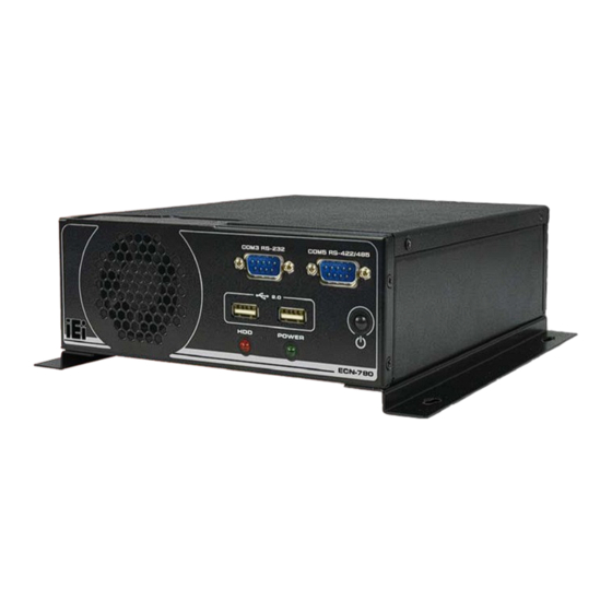
1.1 Ove rvie w Figure 1-1: ECN-780-Q67 The ECN-780-Q67 is an embedded system with one VGA port, one DVI port and one HDMI port for dual display. It is powered by a 2nd generation Intel® Core™ i7/i5/i3, Celeron®, Pentium® desktop processor and uses the Intel® Q67 chipset. It has 2.0 GB DDR3 memory on board and supports one 204-pin 1066/1333 MHz dual-channel DDR3 SDRAM SO-DIMM module up to 10 GB. -
Page 16: Technical Specifications
ECN-780-Q67 Em b e dd e d S ys te m Intel® HD graphics supports H.264/AVC-MPEG2/VC1, DirectX 10.1 and OpenGL 3.0 On-board 2GB DDR3 memory and one DDR3 SO-DIMM slot (system max. 10 Dual Gigabit Ethernet with Intel® AMT 7.0 support ... - Page 17 ECN-780-Q67 Em b e d d e d S ys te m S ys te m Fu n c tio n 2 x USB 3.0 on rear side US B 2 x USB 2.0 on front side 2 x RJ-45 Gigabit LAN...
-
Page 18: Front Panel
CE/FCC S a fe ty & EMC Table 1-2: Technical Specifications 1.5 Fro n t P a n e l The front panel of the ECN-780-Q67 has the following features (Figure 1-2): 1 x HDD LED 1 x Power button ... -
Page 19: Figure 1-3: Ecn-780-Q67 Rear Panel
ECN-780-Q67 Em b e d d e d S ys te m 1 x RS-232 DB-9 connector (COM1) 1 x DVI-D port 1 x HDMI port 1 x Reset button 2 x RJ-45 LAN connectors ... -
Page 20: Dimensions
ECN-780-Q67 Em b e dd e d S ys te m 1.7 Dim e n s io n s The physical dimensions are shown below: Figure 1-4: Physical Dimensions (mm) P a g e 7... -
Page 21: Unpacking
ECN-780-Q67 Em b e d d e d S ys te m Ch a p te r Un p a c kin g P a g e 8... -
Page 22: Anti - Static Precautions
ECN-780-Q67 and severe injury to the user. Electrostatic discharge (ESD) can cause serious damage to electronic components, including the ECN-780-Q67. Dry climates are especially susceptible to ESD. It is therefore critical that whenever the ECN-780-Q67 or any other electrical component is handled, the following anti-static precautions are strictly adhered to. -
Page 23: Unpacking Checklist
ECN-780-Q67 Em b e d d e d S ys te m 2.3 Un pa c kin g Ch e c klis t NOTE: If some of the components listed in the checklist below are missing, please do not proceed with the installation. Contact the IEI reseller or vendor you purchased the ECN-780-Q67 from or contact an IEI sales representative directly. -
Page 24: Table 2-1: Package List Contents
ECN-780-Q67 Em b e dd e d S ys te m Qu a n tity Ite m a n d P a rt Nu m b e r Im a g e Thermal pad (P/N: 34100-000197-RS) Utility CD One Key Recovery CD... -
Page 25: Installation
ECN-780-Q67 Em b e d d e d S ys te m Ch a p te r In s ta lla tio n P a g e 12... -
Page 26: Installation Precautions
Electric shock and personal injury might occur if the rear panel of the ECN-780-Q67 is opened while the power cord is still connected to an electrical outlet. -
Page 27: Figure 3-1: Retention Screws Removal
ECN-780-Q67 Em b e d d e d S ys te m Figure 3-1: Retention Screws Removal S te p 2: Open the HDD cover and locate the HDD bracket (Figure 3-2). Figure 3-2: HDD Bracket P a g e 14... -
Page 28: At/Atx Mode Selection
3.4 AT/ATX Mo d e S e le c tio n AT or ATX power mode can be used on the ECN-780-Q67. The selection is made through an AT/ATX switch located on the rear panel (Figure 3-4). To select AT mode or ATX mode, follow the steps below. -
Page 29: At Power Mode
3.4.2 ATX P owe r Mo d e With the ATX mode selected, the ECN-780-Q67 panel PC goes in a standby mode when it is turned off. The panel PC can be easily turned on via network or a power switch in standby mode. -
Page 30: Reset The System
ECN-780-Q67 Em b e dd e d S ys te m Point-of-Sale (POS) Advertising terminal 3.5 Re s e t th e S ys te m The reset button enables user to reboot the system when the system is turned on. To reboot the system, follow the steps below. -
Page 31: Mount The System
ECN-780-Q67 Em b e d d e d S ys te m Figure 3-6: Power Button Location 3.7 Mo u n t th e S ys te m The ECN-780-Q67 supports wall mounting. The bottom panel of the ECN-780-Q67 contains four screw holes for mounting (Figure 3-7) the system. -
Page 32: Mounting The System With Mounting Brackets
ECN-780-Q67 Em b e dd e d S ys te m 3.7.1 Mo u n tin g th e S ys te m with Mo u n tin g Bra c ke ts To mount the embedded system onto a wall or some other surface using the two mounting brackets, please follow the steps below. -
Page 33: External Peripheral Interface Connectors
ECN-780-Q67 Em b e d d e d S ys te m NOTE: To have the best system heat dissipation, please make sure to face the I/O panel downward (Figure 3-8) when mounting the system. Insert four retention screws, two in each bracket, to secure the system to the S te p 6: wall. -
Page 34: Audio Connection
Figure 3-10: Peripheral Connectors (Rear Panel) 3.8.1 Au d io Co n n e c tio n The audio jacks on the external audio connector enable the ECN-780-Q67 to be connected to a stereo sound setup. To install the audio devices, follow the steps below. -
Page 35: Dvi Display Device Connection
3.8.2 DVI Dis p la y De vic e Co n n e c tio n The ECN-780-Q67 has one female DVI connector on the rear panel. The DVI connectors are connected to digital display devices. To connect a digital display device to the ECN-780-Q67, please follow the instructions below. -
Page 36: Hdmi Device Connection
3.8.3 HDMI De vic e Co n n e c tio n The HDMI connector transmits a digital signal to compatible HDMI display devices such as a TV or computer screen. To connect the HDMI cable to the ECN-780-Q67, follow the steps below. -
Page 37: Lan Connection
ECN-780-Q67 Em b e d d e d S ys te m Align the connector. Align the HDMI connector with the HDMI port. Make sure S te p 2: the orientation of the connector is correct. Figure 3-13: HDMI Connection S te p 3: Insert the HDMI connector. -
Page 38: Serial Port Connection
3.8.5 DB-9 S e ria l P o rt Co n n e c tio n There are two RS-232 DB-9 connectors and one RS-422/485 connector of the ECN-780-Q67 for serial device connection. Follow the steps below to connect a serial device to the DB-9 connector of the ECN-780-Q67. -
Page 39: Usb Device Connection
There are two USB 2.0 connectors and two USB 3.0 connectors on the ECN-780-Q67. To connect a USB device, please follow the instructions below. Locate the USB connectors. The locations of the USB connectors are shown S te p 1: in Chapter 1. -
Page 40: Vga Monitor Connection
3.8.7 VGA Mo n ito r Co n n e c tio n The ECN-780-Q67 has a single female DB-15 connector on the external peripheral interface panel. The DB-15 connector is connected to a CRT or VGA monitor. To connect a monitor to the ECN-780-Q67, please follow the instructions below. -
Page 41: Intel ® Amt Setup Procedure
ECN-780-Q67 Em b e d d e d S ys te m Insert the VGA connector. Once the connectors are properly aligned with the S te p 3: insert the male connector from the VGA screen into the female connector on the ECN-780-Q67. - Page 42 ECN-780-Q67 Em b e dd e d S ys te m S te p 4: Properly install the Intel® Management Engine Components drivers from the iAMT Driver & Utility directory in the driver CD. Configure the Intel® Management Engine BIOS extension (MEBx). To get into S te p 5: the Intel®...
-
Page 43: System Motherboard
ECN-780-Q67 Em b e d d e d S ys te m Ch a p te r S ys te m Mo th e rb o a rd P a g e 30... -
Page 44: Overview
ECN-780-Q67 Em b e dd e d S ys te m 4.1 Ove rvie w The ECN-780-Q671 embedded system motherboard comes with a number of peripheral interface connectors and configuration jumpers. 4.1.1 La yo u t The connector locations are shown in Figure 4-1. The connector pinouts for these connectors are listed in the following sections. -
Page 45: Motherboard Dimensions
ECN-780-Q67 Em b e d d e d S ys te m Figure 4-2: Connector and Jumper Locations (Rear Side) 4.1.2 Mo th e rb o a rd Dim e n s io n s The main dimensions of the system motherboard are shown in the diagram below. -
Page 46: Peripheral Interface Connectors
4.1.3 P e rip h e ra l In te rfa c e Co n n e c to rs The table below shows a list of the peripheral interface connectors on the ECN-780-Q67. Detailed descriptions of these connectors can be found below. -
Page 47: Internal Peripheral Connectors
ECN-780-Q67 Em b e d d e d S ys te m Co n n e c to r Typ e La b e l Power connector 2-pin wafer DC_IN1 RS-232 serial ports 10-pin header COM1, COM2, COM3, COM4 RS-422/485 serial port... -
Page 48: Bios Programming Connector
ECN-780-Q67 Em b e dd e d S ys te m Figure 4-5: Battery Connector Location Description VBATT Table 4-2: Battery Connector Pinouts 4.2.2 BIOS P ro g ra m m in g Co n n e c to r... -
Page 49: Digital I/O Connector
ECN-780-Q67 Em b e d d e d S ys te m Figure 4-6: BIOS Programming Connector Location PIN NO. DESCRIPTION PIN NO. DESCRIPTION SPI_VCC SPI_CS#0_CN SPI_SO0_CN SPI_CLK0_CN SPI_SI0_CN Table 4-3: BIOS Programming Connector Pinouts 4.2.3 Dig ita l I/O Co n n e c to r... -
Page 50: Ec Programming Connector
ECN-780-Q67 Em b e dd e d S ys te m Figure 4-7: Digital I/O Connector Location PIN NO. DESCRIPTION PIN NO. DESCRIPTION +V5S +V5S DOUT4 DOUT3 DOUT2 DOUT1 DIN4 DIN3 DIN2 DIN1 Table 4-4: Digital I/O Connector Pinouts 4.2.4 EC P ro g ra m m in g Con n e c to r... -
Page 51: Fan Connector (System)
ECN-780-Q67 Em b e d d e d S ys te m Figure 4-8: EC Programming Connector Location PIN NO. DESCRIPTION PIN NO. DESCRIPTION +V3.3A_EC_CONN FSCE#_S FMISO_S FSCK_S FMOSI_S Table 4-5: EC Programming Connector Pinouts 4.2.5 Fa n Co n n e c to r (S ys te m ) -
Page 52: Keyboard/Mouse Connector
ECN-780-Q67 Em b e dd e d S ys te m Figure 4-9: System Fan Connector Location Description +V12S FANPWM1 FANIN1 Table 4-6: System Fan Connector Pinouts 4.2.6 Ke yb o a rd /Mo u s e Co n n e c to r... -
Page 53: Led Module Connector
ECN-780-Q67 Em b e d d e d S ys te m Figure 4-10: Keyboard/Mouse Connector Location Description VCC5_KBMS MSDATA MSCLK KBDATA KBCLK Table 4-7: Keyboard/Mouse Connector Pinouts 4.2.7 LED Mo d u le Co n n e c to r... -
Page 54: Pcie Mini Card Slot
ECN-780-Q67 Em b e dd e d S ys te m Figure 4-11: LED Module Connector Location Description +V5S SATA_LED# +V5A Table 4-8: LED Module Connector Pinouts 4.2.8 P CIe Min i Ca rd S lo t CN La b e l:... -
Page 55: Power Connector
ECN-780-Q67 Em b e d d e d S ys te m Figure 4-12: PCIe Mini Card Slot Location 4.2.9 P owe r Co n n e c to r CN La b e l: DC_IN1 CN Typ e :... -
Page 56: Serial Port Connectors
ECN-780-Q67 Em b e dd e d S ys te m Figure 4-13: Power Connector Location Description Description DC_IN Table 4-9: Power Connector Pinouts 4.2.10 RS -232 S e ria l P o rt Co n n e c to rs... -
Page 57: Rs-422/485 Serial Port Connector
ECN-780-Q67 Em b e d d e d S ys te m Figure 4-14: RS-232 Serial Port Connector Location Figure 4-15: RS-232 Serial Port Connector Location Description Description -NDCD1/2/3/4 -NDSR1/2/3/4 NSIN1/2/3/4 -NRTS1/2/3/4 NSOUT1/2/3/4 -NCTS1/2/3/4 -NDTR1/2/3/4 -XRI1/2/3/4 Table 4-10: Serial Port Connector Pinouts (COM1, COM2, COM3, COM4 ) 4.2.11 RS -422/485 S e ria l P ort Co n n e c to r... -
Page 58: Sata Drive Connectors
ECN-780-Q67 Em b e dd e d S ys te m CN Typ e : 8-pin header CN Lo c a tio n : See Figure 4-16 See Table 4-11 CN P in o u ts : This connector provides RS-422 or RS-485 communications. -
Page 59: Sata Power Connectors
ECN-780-Q67 Em b e d d e d S ys te m Figure 4-17: SATA Drive Connector Locations 4.2.13 S ATA P o we r Co n n e c to rs CN La b e l: CN1, CN2 2-pin wafer... -
Page 60: Smbus Connector
ECN-780-Q67 Em b e dd e d S ys te m Figure 4-18: SATA Power Connector Locations Description +V5S Table 4-12: SATA Power Connector Pinouts 4.2.14 S MBu s Co n n e c to r CN La b e l:... -
Page 61: So-Dimm Connector
ECN-780-Q67 Em b e d d e d S ys te m Figure 4-19: SMBus Connector Location Description SMB_DATA SMB_CLK_A +V5S Table 4-13: SMBus Connector Pinouts 4.2.15 S O-DIMM Co n n e c to r CN La b e l:... -
Page 62: K Type Thermocouple Connectors
ECN-780-Q67 Em b e dd e d S ys te m Figure 4-20: SO-DIMM Connector Locations 4.2.16 K Typ e Th e rm o c o u p le Co n n e c to rs CN La b e l:... -
Page 63: Tpm Connector
ECN-780-Q67 Em b e d d e d S ys te m Description D1-/D2- D1+/D2+ Table 4-14: Type K Thermocouple Connector Pinouts 4.2.17 TP M Co n n e c to r CN La b e l: TPM1 20-pin header... -
Page 64: Usb 2.0 Connectors
ECN-780-Q67 Em b e dd e d S ys te m PIN NO. DESCRIPTION PIN NO. DESCRIPTION +V3.3A INT_SERIRQ PM_CLKRUN# LPCPD# SIO_DRQ#0 Table 4-15: TPM Connector Pinouts 4.2.18 US B 2.0 Co n n e c to rs CN La b e l:... -
Page 65: Vga Connector
ECN-780-Q67 Em b e d d e d S ys te m VCC_USB23/45 Table 4-16: USB Port Connector Pinouts 4.2.19 VGA Co n n e c to r CN La b e l: VGA1 10-pin header CN Typ e :... -
Page 66: Jumper Settings
J u m p e r Lo c a tio n : See Figure 4-25 If the ECN-780-Q67 fails to boot due to improper BIOS settings, the clear CMOS jumper clears the CMOS data and resets the system BIOS information. To do this, use the jumper cap to close pins 2 and 3 for a few seconds then reinstall the jumper clip back to pins 1 and 2. -
Page 67: Flash Descriptor Security Override
ECN-780-Q67 Em b e dd e d S ys te m Description Short 1-2 Keep CMOS Setup (Default) Short 2-3 Clear CMOS Setup Table 4-19: Clear CMOS Jumper Settings Figure 4-25: Clear CMOS Jumper Location 4.3.2 Fla s h De s c rip to r S e c u rity Ove rrid e... -
Page 68: Figure 4-26: Flash Descriptor Security Override Jumper Location
ECN-780-Q67 Em b e dd e d S ys te m Figure 4-26: Flash Descriptor Security Override Jumper Location P a g e 55... -
Page 69: Bios
ECN-780-Q67 Em b e d d e d S ys te m Ch a p te r BIOS P a g e 56... -
Page 70: Introduction
ECN-780-Q67 Em b e dd e d S ys te m 5.1 In tro d u c tio n The BIOS is programmed onto the BIOS chip. The BIOS setup program allows changes to certain system settings. This chapter outlines the options that can be changed. -
Page 71: Getting Help
ECN-780-Q67 Em b e d d e d S ys te m Ke y Fu n c tio n F4 key Save all the CMOS changes Table 5-1: BIOS Navigation Keys 5.1.3 Ge ttin g He lp When F1 is pressed a small help window describing the appropriate keys to use and the possible selections for the highlighted item appears. -
Page 72: Main
ECN-780-Q67 Em b e dd e d S ys te m 5.2 Ma in The Main BIOS menu (BIOS Menu 1) appears when the BIOS Setup program is entered. The Main menu gives an overview of the basic system information. -
Page 73: Advanced
ECN-780-Q67 Em b e d d e d S ys te m iWDD Ve rs io n The iWDD Version displays the current iWDD version. The fields in iWDD Version cannot be changed. Me m o ry In fo rm a tio n The Memory Information lists a brief summary of the on-board memory. -
Page 74: Acpi Configuration
ECN-780-Q67 Em b e dd e d S ys te m Aptio Setup Utility – Copyright (C) 2009 American Megatrends, Inc. Main Advanced Chipset Boot Security Save & Exit > ACPI Settings System ACPI Parameters > RTC Wake Settings > Trusted Computing >... -
Page 75: Rtc Wake Settings
ECN-780-Q67 Em b e d d e d S ys te m ACP I S le e p Sta te [S 1 (CP U Sto p Clo c k)] Use the ACPI Sleep State option to specify the sleep state the system enters when it is not being used. -
Page 76: Trusted Computing
ECN-780-Q67 Em b e dd e d S ys te m The real time clock (RTC) cannot generate a wake Disabled EFAULT event Enabled If selected, the Wake up every day option appears allowing you to enable to disable the system to wake every day at the specified time. -
Page 77: Cpu Configuration
ECN-780-Q67 Em b e d d e d S ys te m TPM S u p p o rt [Dis a b le ] Use the TPM Support option to configure support for the TPM. TPM support is disabled. -
Page 78: Cpu Information
ECN-780-Q67 Em b e dd e d S ys te m In te l Virtu a liza tio n Te c h n o lo g y [En a b le d ] Use the Intel Virtualization Technology option to enable or disable virtualization on the system. -
Page 79: Sata Configuration
ECN-780-Q67 Em b e d d e d S ys te m Processor Cores: Lists the number of the processor core Intel HT Technology: Indicates if Intel HT Technology is supported by the CPU. Intel VT-x Technology: Indicates if Intel VT-x Technology is supported by the CPU. -
Page 80: Intel Txt (Lt) Configuration
ECN-780-Q67 Em b e dd e d S ys te m Configures SATA devices as AHCI device. AHCI Mode S e ria l-ATA Co n tro lle r 0 [Co m pa tib le ] Use the Serial-ATA Controller option to configure the Serial-ATA controller mode when the SATA mode is set to IDE Mode. -
Page 81: Usb Configuration
ECN-780-Q67 Em b e d d e d S ys te m 5.3.7 US B Co n fig u ra tio n Use the USB Configuration menu (BIOS Menu 10) to read USB configuration information and configure the USB settings. -
Page 82: F81866 Super Io Configuration
ECN-780-Q67 Em b e dd e d S ys te m Legacy USB support enabled Enabled EFAULT Auto Legacy USB support disabled if no USB devices are connected 5.3.8 F81866 S u pe r IO Co nfig u ra tio n Use the F81866 Super IO Configuration menu (BIOS Menu 11) to set or change the configurations for the FDD controllers, parallel ports and serial ports. -
Page 83: Serial Port N Configuration
ECN-780-Q67 Em b e d d e d S ys te m 5.3.8.1 S e ria l P o rt n Co n fig u ra tio n Use the Serial Port n Configuration menu (BIOS Menu 12) to configure the serial port n. - Page 84 ECN-780-Q67 Em b e dd e d S ys te m Serial Port I/O port address is 3F8h and the interrupt IO=3F8h; IRQ=3, 4 address is IRQ3, 4 IO=2F8h; Serial Port I/O port address is 2F8h and the interrupt...
- Page 85 ECN-780-Q67 Em b e d d e d S ys te m Serial Port I/O port address is 2E8h and the interrupt IO=2E8h; IRQ=3, 4 address is IRQ3, 4 5.3.8.1.3 S e ria l P o rt 3 Co n fig u ra tio n ...
- Page 86 ECN-780-Q67 Em b e dd e d S ys te m 5.3.8.1.4 S e ria l P o rt 4 Co n fig u ra tio n S e ria l P o rt [En a b le d ] Use the Serial Port option to enable or disable the serial port.
-
Page 87: F81866 H/W Monitor
ECN-780-Q67 Em b e d d e d S ys te m Enable the serial port Enabled EFAULT Ch a n g e S e ttin g s [Au to ] Use the Change Settings option to change the serial port IO port address and interrupt address. - Page 88 ECN-780-Q67 Em b e dd e d S ys te m Aptio Setup Utility – Copyright (C) 2009 American Megatrends, Inc. Advanced PC Health Status Smart Fan Mode Select > CPU_FAN1 Smart Fan Mode Configuration CPU Temperature :+46 C Accuracy:1.(-5~+10)degree around 100 degree 2.(-10~+15)degree around 50 degree...
-
Page 89: Smart Fan Mode Configuration
ECN-780-Q67 Em b e d d e d S ys te m VBAT 5.3.9.1 S m a rt Fa n Mo d e Co nfig u ra tio n Use the Smart Fan Mode Configuration menu (BIOS Menu 14) to configure the CPU fan. - Page 90 ECN-780-Q67 Em b e dd e d S ys te m Te m p e ra tu re o f Sta rt [75] WARNING: Setting this value too high may cause the fan to rotate at full speed only when the CPU is at a very high temperature and therefore cause the system to be damaged.
-
Page 91: Serial Port Console Redirection
ECN-780-Q67 Em b e d d e d S ys te m The Start PWM option can only be set if the CPU Smart Fan control option is set to Auto Mode. Use the Start PWM option to set the PWM start value. To set a value, select the Start PWM option and enter a decimal number between 0 and 100. -
Page 92: Console Redirection Settings
ECN-780-Q67 Em b e dd e d S ys te m Aptio Setup Utility – Copyright (C) 2009 American Megatrends, Inc. Advanced COM1 Console Redirection Console Redirection [Disabled] Enable or Disable. > Console Redirection Settings --------------------- : Select Screen COM2 ↑... - Page 93 ECN-780-Q67 Em b e d d e d S ys te m Aptio Setup Utility – Copyright (C) 2009 American Megatrends, Inc. Advanced COM1 Emulation: ANSI: Console Redirection Settings Extended ASCII char set. VT100: ASCII char set. Terminal Type [ANSI]...
-
Page 94: I E I Feature
ECN-780-Q67 Em b e dd e d S ys te m The transmission speed is 57600 57600 115200 The transmission speed is 115200 EFAULT 5.4 iEi Fe a tu re Use the iEi Feature menu (BIOS Menu 17) to configure the auto recovery function. -
Page 95: Chipset
ECN-780-Q67 Em b e d d e d S ys te m 5.5 Ch ips e t Use the Chipset menu (BIOS Menu 18) to access the Northbridge and Southbridge configuration menus WARNING! Setting the wrong values for the Chipset BIOS selections in the Chipset BIOS menu may cause the system to malfunction. -
Page 96: Northbridge Configuration
ECN-780-Q67 Em b e dd e d S ys te m 5.5.1 No rth b rid g e Co n fig u ra tio n Use the Northbridge Chipset Configuration menu (BIOS Menu 19) to configure the Northbridge chipset. Aptio Setup Utility – Copyright (C) 2009 American Megatrends, Inc. -
Page 97: Southbridge Configuration
ECN-780-Q67 Em b e d d e d S ys te m 128 MB of memory used by internal graphics 128 M EFAULT device 256 M 256 MB of memory used by internal graphics device 512 M... - Page 98 ECN-780-Q67 Em b e dd e d S ys te m Aza lia HD Au d io [En a b le d ] Use the Azalia HD Audio option to enable or disable the High Definition Audio controller. ...
-
Page 99: Intel Igd Swsci Opregion
ECN-780-Q67 Em b e d d e d S ys te m 5.5.3 In te l IGD S WS CI Op Re g io n Use the Intel IGD SWSCI OpRegion menu to configure the video device connected to the system. -
Page 100: Me Subsystem
ECN-780-Q67 Em b e dd e d S ys te m Maximum EFAULT IGD - Bo o t Typ e [VBIOS De fa u lt] Use the IGD - Boot Type option to select the display device used by the system when it boots. -
Page 101: Boot
ECN-780-Q67 Em b e d d e d S ys te m Enables hidden Ctrl+P function Hidden Ctrl + P Enter Enables user to enter MEBx setup MEBx Setup Un c o n fig u re AMT/ME [En a b le d ] Use the Unconfigure AMT/ME option to perform AMT/ME unconfigure without password operation. - Page 102 ECN-780-Q67 Em b e dd e d S ys te m Does not enable the keyboard Number Lock automatically. To use the 10-keys on the keyboard, press the Number Lock key located on the upper left-hand corner of the 10-key pad. The Number Lock LED on the keyboard lights up when the Number Lock is engaged.
-
Page 103: Security
ECN-780-Q67 Em b e d d e d S ys te m Bo o t Op tio n P rio ritie s Use the Boot Option Priorities function to set the system boot sequence from the available devices. The drive sequence also depends on the boot sequence in the individual device section. -
Page 104: Exit
ECN-780-Q67 Em b e dd e d S ys te m 5.8 Exit Use the Exit menu (BIOS Menu 25) to load default BIOS values, optimal failsafe values and to save configuration changes. Aptio Setup Utility – Copyright (C) 2009 American Megatrends, Inc. - Page 105 ECN-780-Q67 Em b e d d e d S ys te m S a ve a s Us e r De fa u lts Use the Save as User Defaults option to save the changes done so far as user defaults.
-
Page 106: Software Drivers
ECN-780-Q67 Em b e dd e d S ys te m Chapter S o ftwa re Drive rs P a g e 93... -
Page 107: Available Software Drivers
ECN-780-Q67 Em b e d d e d S ys te m 6.1 Ava ila b le S o ftwa re Drive rs NOTE: The content of the CD may vary throughout the life cycle of the product and is subject to change without prior notice. Visit the IEI website or contact technical support for the latest updates. -
Page 108: Chipset Driver Installation
ECN-780-Q67 Em b e dd e d S ys te m Figure 6-1: Drivers 6.3 Ch ips e t Drive r In s ta lla tio n To install the chipset driver, please do the following. S te p 1: Access the driver list. -
Page 109: Figure 6-2: Chipset Driver Screen
ECN-780-Q67 Em b e d d e d S ys te m Figure 6-2: Chipset Driver Screen When the setup files are completely extracted the Welcome Screen in Figure S te p 5: 6-3 appears. S te p 6: Click Next to continue. -
Page 110: Figure 6-4: Chipset Driver License Agreement
ECN-780-Q67 Em b e dd e d S ys te m Read the License Agreement. S te p 8: Click Yes to continue. S te p 9: Figure 6-4: Chipset Driver License Agreement The Read Me file in Figure 6-5 appears. -
Page 111: Figure 6-5: Chipset Driver Read Me File
ECN-780-Q67 Em b e d d e d S ys te m Figure 6-5: Chipset Driver Read Me File Setup Operations are performed as shown in Figure 6-6. S te p 12: Once the Setup Operations are complete, click Next to continue. -
Page 112: Graphics Driver Installation
ECN-780-Q67 Em b e dd e d S ys te m Select “Yes, I want to restart this computer now” and click Finish.S te p 0: S te p 15: Figure 6-7: Chipset Driver Installation Finish Screen 6.4 Gra p h ic s Drive r In s ta lla tio n To install the Graphics driver, please do the following. -
Page 113: Figure 6-8: Graphics Driver Read Me File
ECN-780-Q67 Em b e d d e d S ys te m Figure 6-8: Graphics Driver Read Me File The installation files are extracted. See Figure 6-9. S te p 6: Click Next to continue. S te p 7: Figure 6-9: Graphics Driver Setup Files Extracted The Welcome Screen in Figure 6-10 appears. -
Page 114: Figure 6-10: Graphics Driver Welcome Screen
ECN-780-Q67 Em b e dd e d S ys te m Figure 6-10: Graphics Driver Welcome Screen The License Agreement in Figure 6-11 appears. S te p 10: Click Yes to accept the agreement and continue. S te p 11: Figure 6-11: Graphics Driver License Agreement The Read Me file in Figure 6-12 appears. -
Page 115: Figure 6-12: Graphics Driver Read Me File
ECN-780-Q67 Em b e d d e d S ys te m Figure 6-12: Graphics Driver Read Me File Setup Operations are performed as shown in Figure 6-13. S te p 14: Once the Setup Operations are complete, click Next to continue. -
Page 116: Lan Driver Installation
ECN-780-Q67 Em b e dd e d S ys te m Figure 6-14: Graphics Driver Installation Finish Screen 6.5 LAN Drive r In s ta lla tio n To install the LAN driver, please do the following. S te p 1: Access the driver list. -
Page 117: Figure 6-15: Intel® Network Connection Menu
ECN-780-Q67 Em b e d d e d S ys te m Figure 6-15: Intel® Network Connection Menu S te p 6: The Welcome screen in Figure 6-16 appears. Figure 6-16: LAN Driver Welcome Screen Click Next to continue. S te p 7: The License Agreement in Figure 6-17 appears. -
Page 118: Figure 6-17: Lan Driver License Agreement
ECN-780-Q67 Em b e dd e d S ys te m Click Next to continue. S te p 10: Figure 6-17: LAN Driver License Agreement The Setup Options screen in Figure 6-18 appears. S te p 11: Select program features to install. -
Page 119: Figure 6-19: Lan Driver Installation
ECN-780-Q67 Em b e d d e d S ys te m The Ready to Install the Program screen in Figure 6-19 appears. S te p 14: Click Install to proceed with the installation. S te p 15: Figure 6-19: LAN Driver Installation The program begins to install. -
Page 120: Audio Driver Installation
ECN-780-Q67 Em b e dd e d S ys te m 6.6 Au d io Drive r In s ta lla tio n To install the audio driver, please do the following. S te p 1: Access the driver list. (See Section 6.2) Click “Audio”... -
Page 121: Figure 6-22: Audio Driver Installation
ECN-780-Q67 Em b e d d e d S ys te m Figure 6-22: Audio Driver Installation When the installation is complete, the screen in Figure 6-23 appears. S te p 7: Select “Yes, I want to restart my computer now” and click Finish. -
Page 122: Usb 3.0 Driver Installation
ECN-780-Q67 Em b e dd e d S ys te m 6.7 US B 3.0 Drive r In s ta lla tio n To install the USB 3.0 driver, please do the following. S te p 1: Access the driver list. (See Section 6.2) Click “USB 3.0”... -
Page 123: Figure 6-25: Usb 3.0 Driver Choose Install Location
ECN-780-Q67 Em b e d d e d S ys te m Figure 6-25: USB 3.0 Driver Choose Install Location The program is ready to install (Figure 6-26). S te p 8: Click I to continue. S te p 9: NS TALL Figure 6-26: USB 3.0 Driver Choose Install Location... -
Page 124: Intel ® Management Engine Components Installation
ECN-780-Q67 Em b e dd e d S ys te m When the driver installation is complete, the screen in Figure 6-27 appears. S te p 10: Click Finish to exit. S te p 11: S te p 0: Figure 6-27: USB 3.0 Driver Installation Complete 6.8 In te l®... -
Page 125: Figure 6-28: Intel® Me Driver Welcome Screen
ECN-780-Q67 Em b e d d e d S ys te m 6-28 appears. Click Next to continue. S te p 5: Figure 6-28: Intel® ME Driver Welcome Screen The license agreement in Figure 6-29 appears. S te p 6: S te p 7: Read the License Agreement. -
Page 126: Figure 6-29: Intel® Me Driver License Agreement
ECN-780-Q67 Em b e dd e d S ys te m Figure 6-29: Intel® ME Driver License Agreement The Read Me file in Figure 6-30 appears. S te p 9: Click Next to continue. S te p 10: Figure 6-30: Intel® ME Driver Read Me File... -
Page 127: Figure 6-31: Intel® Me Driver Setup Operations
ECN-780-Q67 Em b e d d e d S ys te m Setup Operations are performed as shown in Figure 6-31. S te p 11: Once the Setup Operations are complete, click Next to continue. S te p 12: Figure 6-31: Intel® ME Driver Setup Operations The Finish screen in Figure 6-32 appears. -
Page 128: Figure 6-32: Intel® Me Driver Installation Finish Screen
ECN-780-Q67 Em b e dd e d S ys te m Figure 6-32: Intel® ME Driver Installation Finish Screen P a g e 115... -
Page 129: A Safety Precautions
ECN-780-Q67 Em b e d d e d S ys te m Appendix S a fe ty P re c a u tio n s P a g e 116... -
Page 130: Safety Precautions
Do not apply voltage levels that exceed the specified voltage range. Doing so may cause fire and/or an electrical shock. Electric shocks can occur if the ECN-780-Q67 chassis is opened when the ECN-780-Q67 is running. Do not drop or insert any objects into the ventilation openings of the ECN-780-Q67. -
Page 131: Anti-Static Precautions
Electrostatic discharge (ESD) can cause serious damage to electronic components, including the ECN-780-Q67. Dry climates are especially susceptible to ESD. It is therefore critical that whenever the ECN-780-Q67 is opened and any of the electrical components are handled, the following anti-static precautions are strictly adhered to. -
Page 132: Product Disposal
When maintaining or cleaning the ECN-780-Q67, please follow the guidelines below. A.2.1 Ma in te n a n c e a n d Cle a n in g Prior to cleaning any part or component of the ECN-780-Q67, please read the details below. -
Page 133: Cleaning Tools
Some components in the ECN-780-Q67 may only be cleaned using a product specifically designed for the purpose. In such case, the product will be explicitly mentioned in the cleaning tips. Below is a list of items to use when cleaning the ECN-780-Q67. ... -
Page 134: B Bios Menu Options
ECN-780-Q67 Em b e dd e d S ys te m Appendix BIOS Me n u Op tio n s P a g e 121... - Page 135 ECN-780-Q67 Em b e d d e d S ys te m BIOS Information .........................59 iWDD Vendor ........................59 iWDD Version ........................60 Memory Information ......................60 System Date [xx/xx/xx] ......................60 System Time [xx:xx:xx] .......................60 ACPI Sleep State [S1 (CPU Stop Clock)] ................62 ...
- Page 136 ECN-780-Q67 Em b e dd e d S ys te m Bits per second [115200] .....................80 Auto Recovery Function [Disabled] ...................81 VT-d [Disabled] ........................83 IGD Memory [128M] ......................83 Restore AC Power Loss [Last State] .................84 ...
-
Page 137: C One Key Recovery
ECN-780-Q67 Em b e d d e d S ys te m Ap p e n d ix On e Ke y Re c o ve ry P a g e 124... -
Page 138: One Key Recovery Introduction
ECN-780-Q67 Em b e dd e d S ys te m C.1 On e Ke y Re c o ve ry In tro d u c tio n The IEI one key recovery is an easy-to-use front end for the Norton Ghost system backup and recovery tool. -
Page 139: System Requirement
ECN-780-Q67 Em b e d d e d S ys te m After completing the five initial setup procedures as described above, users can access the recovery tool by pressing <F3> while booting up the system. The detailed information of each function is described in Section C.5. -
Page 140: Supported Operating System
ECN-780-Q67 Em b e dd e d S ys te m partitions. Please take the following table as a reference when calculating the size of the partition. OS Image after Ghost Compression Ratio Windows® 7 7 GB 5 GB Windows® XPE... -
Page 141: Setup Procedure For Windows
ECN-780-Q67 Em b e d d e d S ys te m Ubuntu 8.10 (Intrepid) Ubuntu 7.10 (Gutsy) Ubuntu 6.10 (Edgy) Debian 5.0 (Lenny) Debian 4.0 (Etch) SuSe 11.2 SuSe 10.3 NOTE: Installing unsupported OS versions may cause the recovery tool to fail. -
Page 142: Hardware And Bios Setup
ECN-780-Q67 Em b e dd e d S ys te m C.2.1 Ha rdwa re a n d BIOS S e tu p Make sure the system is powered off and unplugged. S te p 1: Install a hard drive or SSD in the system. An unformatted and unpartitioned disk S te p 2: is recommended. -
Page 143: Figure C-2: Launching The Recovery Tool
ECN-780-Q67 Em b e d d e d S ys te m Figure C-2: Launching the Recovery Tool S te p 3: The recovery tool setup menu is shown as below. Figure C-3: Recovery Tool Setup Menu S te p 4: Press <6>... -
Page 144: Figure C-4: Command Prompt
ECN-780-Q67 Em b e dd e d S ys te m Figure C-4: Command Prompt S te p 5: The command prompt window appears. Type the following commands (marked in red) to create two partitions. One is for the OS installation; the other is for saving recovery files and images which will be an invisible partition. -
Page 145: Figure C-5: Partition Creation Commands
ECN-780-Q67 Em b e d d e d S ys te m Figure C-5: Partition Creation Commands P a g e 132... -
Page 146: Install Operating System, Drivers And Applications
ECN-780-Q67 Em b e dd e d S ys te m NOTE: Use the following commands to check if the partitions were created successfully. S te p 6: Press any key to exit the recovery tool and automatically reboot the system. -
Page 147: Building The Recovery Partition
ECN-780-Q67 Em b e d d e d S ys te m C.2.4 Bu ild in g th e Re c o ve ry P a rtitio n Put the recover CD in the optical drive. S te p 1: Start the system. -
Page 148: Figure C-8: Building The Recovery Partition
ECN-780-Q67 Em b e dd e d S ys te m S te p 5: The Symantec Ghost window appears and starts configuring the system to build a recovery partition. In this process the partition created for recovery files in Section C.2.2 is hidden and the recovery tool is saved in this partition. -
Page 149: Create Factory Default Image
ECN-780-Q67 Em b e d d e d S ys te m C.2.5 Cre a te Fa c to ry De fa u lt Im a g e NOTE: Before creating the factory default image, please configure the system to a factory default environment, including driver and application installations. -
Page 150: Figure C-12: About Symantec Ghost Window
ECN-780-Q67 Em b e dd e d S ys te m Figure C-12: About Symantec Ghost Window Use mouse to navigate to the option shown below (Figure C-13). S te p 4: Figure C-13: Symantec Ghost Path S te p 5: Select the local source drive (Drive 1) as shown in Figure C-14. -
Page 151: Figure C-14: Select A Local Source Drive
ECN-780-Q67 Em b e d d e d S ys te m Figure C-14: Select a Local Source Drive S te p 6: Select a source partition (Part 1) from basic drive as shown in Figure C-15. Then click OK. -
Page 152: Figure C-16: File Name To Copy Image To
ECN-780-Q67 Em b e dd e d S ys te m Figure C-16: File Name to Copy Image to When the Compress Image screen in Figure C-17 prompts, click High to make S te p 8: the image file smaller. -
Page 153: Figure C-18: Image Creation Confirmation
ECN-780-Q67 Em b e d d e d S ys te m The Proceed with partition image creation window appears, click Yes to S te p 9: continue. Figure C-18: Image Creation Confirmation The Symantec Ghost starts to create the factory default image (Figure C-19). -
Page 154: Auto Recovery Setup Procedure
ECN-780-Q67 Em b e dd e d S ys te m S te p 12: The recovery tool main menu window is shown as below. Press any key to reboot the system. S t e p 0 : Figure C-21: Press Any Key to Continue C.3 Au to Re c o ve ry S e tu p P ro c e d u re... -
Page 155: Figure C-22: Auto Recovery Utility
ECN-780-Q67 Em b e d d e d S ys te m Figure C-22: Auto Recovery Utility Reboot the system from the recovery CD. When prompted, press any key to S te p 3: boot from the recovery CD. It will take a while to launch the recovery tool. Please... -
Page 156: Figure C-25: Building The Auto Recovery Partition
ECN-780-Q67 Em b e dd e d S ys te m S te p 5: The Symantec Ghost window appears and starts configuring the system to build an auto recovery partition. In this process the partition created for recovery files in Section C.2.2 is hidden and the auto recovery tool is saved in this partition. -
Page 157: Figure C-27: Image Creation Complete
ECN-780-Q67 Em b e d d e d S ys te m The Symantec Ghost starts to create the factory default image (Figure C-27). S te p 7: Figure C-27: Image Creation Complete S te p 8: After completing the system configuration, press any key in the following window to restart the system. -
Page 158: Setup Procedure For Linux
ECN-780-Q67 Em b e dd e d S ys te m BIOS SETUP UTILITY Main Advanced PCIPNP Boot Security Chipset Exit iEi Feature Auto Recovery Function [Enabled] Recover from PXE [Disabled] Select Screen ↑ ↓ Select Item Enter Go to SubScreen... -
Page 159: Figure C-29: Partitions For Linux
ECN-780-Q67 Em b e d d e d S ys te m Install Linux operating system. Make sure to install GRUB (v0.97 or earlier) S te p 2: MBR type and Ext3 partition type. Leave enough space on the hard drive to create the recover partition later. -
Page 160: Figure C-30: Manual Recovery Environment For Linux
ECN-780-Q67 Em b e dd e d S ys te m DISKPART>create part pri size= DISKPART>assign letter=N DISKPART>exit system32>format N: /fs:ntfs /q /v:Recovery /y system32>exit Build the recovery partition. Press any key to boot from the recovery CD. It will S te p 4: take a while to launch the recovery tool. -
Page 161: Figure C-31: Access Menu.lst In Linux (Text Mode)
ECN-780-Q67 Em b e d d e d S ys te m Figure C-31: Access menu.lst in Linux (Text Mode) Modify the menu.lst as shown below. S te p 6: The recovery tool menu appears. (Figure C-32) S te p 7: Figure C-32: Recovery Tool Menu Create a factory default image. -
Page 162: Recovery Tool Functions
ECN-780-Q67 Em b e dd e d S ys te m C.5 Re c o ve ry To o l Fu n c tio n s After completing the initial setup procedures as described above, users can access the recovery tool by pressing <F3> while booting up the system. However, if the setup procedure in Section C.3 has been completed and the auto recovery function is enabled,... -
Page 163: Factory Restore
ECN-780-Q67 Em b e d d e d S ys te m WARNING: All data in the system will be deleted during the system recovery. Please backup the system files before restoring the system (either Factory Restore or Restore Backup). -
Page 164: Backup System
ECN-780-Q67 Em b e dd e d S ys te m Figure C-35: Recovery Complete Window C.5.2 Ba c ku p S ys te m To backup the system, please follow the steps below. Type <2> and press <Enter> in the main menu. -
Page 165: Restore Your Last Backup
ECN-780-Q67 Em b e d d e d S ys te m Figure C-37: System Backup Complete Window C.5.3 Re s to re Yo u r La s t Ba c ku p To restore the last system backup, please follow the steps below. -
Page 166: Manual
ECN-780-Q67 Em b e dd e d S ys te m Figure C-39: Restore System Backup Complete Window C.5.4 Ma n u a l To restore the last system backup, please follow the steps below. Type <4> and press <Enter> in the main menu. -
Page 167: Restore Systems From A Linux Server Through Lan
ECN-780-Q67 Em b e d d e d S ys te m C.6 Re s to re S ys te m s fro m a Lin u x S e rve r thro u g h LAN The One Key Recovery allows a client system to automatically restore to a factory default image saved in a Linux system (the server) through LAN connectivity after encountering a Blue Screen of Death (BSoD) or a hang for around 10 minutes. -
Page 168: Configure Dhcp Server Settings
ECN-780-Q67 Em b e dd e d S ys te m C.6.1 Co n fig u re DHCP S e rve r S e ttin g s Install the DHCP S te p 1: #yum install dhcp (CentOS, commands marked in red) -
Page 169: Configure Tftp Settings
ECN-780-Q67 Em b e d d e d S ys te m filename “pxelinux.0”; C.6.2 Co n fig u re TFTP S e ttin g s S te p 1: Install the tftp, httpd and syslinux. #yum install tftp-server httpd syslinux... -
Page 170: Configure One Key Recovery Server Settings
ECN-780-Q67 Em b e dd e d S ys te m Debian Replace the TFTP settings from “inetd” to “xinetd” and annotate the “inetd” by adding “#”. #vi /etc/inetd.conf Modify: #tftp dgram udp wait root /usr/sbin..(as shown below) #vi /etc/xinetd.d/tftp C.6.3 Co n fig u re On e Ke y Re c o ve ry S e rve r S e ttin g s... -
Page 171: Start The Dhcp, Tftp And Http
ECN-780-Q67 Em b e d d e d S ys te m C.6.4 Sta rt th e DHCP, TFTP a n d HTTP Start the DHCP, TFTP and HTTP. For example: CentOS #service xinetd restart #service httpd restart #service dhcpd restart Debian #/etc/init.d/xinetd reload... -
Page 172: Setup A Client System For Auto Recovery
ECN-780-Q67 Em b e dd e d S ys te m Modify: [image] comment = One Key Recovery path = /share/image browseable = yes writable = yes public = yes create mask = 0644 directory mask = 0755 S te p 4: Edit “/etc/samba/smb.conf”... - Page 173 ECN-780-Q67 Em b e d d e d S ys te m Continue to configure the Boot Option Priorities BIOS option of the client S te p 2: system: Boot Option #1 remain the default setting to boot from the original OS.
- Page 174 ECN-780-Q67 Em b e dd e d S ys te m NOTE: A firewall or a SELinux is not in use in the whole setup process. If there is a firewall or a SELinux protecting the system, modify the configuration information to accommodate them.
-
Page 175: Other Information
ECN-780-Q67 Em b e d d e d S ys te m C.7 Oth e r In fo rm a tio n C.7.1 Us in g AHCI Mo d e o r ALi M5283 / VIA VT6421A Co n tro lle r... - Page 176 ECN-780-Q67 Em b e dd e d S ys te m When the following window appears, press <S> to select “Specify Additional S te p 5: Device”. In the following window, select a SATA controller mode used in the system. Then S te p 6: press <Enter>.
-
Page 177: System Memory Requirement
ECN-780-Q67 Em b e d d e d S ys te m S te p 7: After pressing <Enter>, the system will get into the recovery tool setup menu. Continue to follow the setup procedure from Step 4 in Section C.2.2 Create Partitions to finish the whole setup process. -
Page 178: D Watchdog Timer
ECN-780-Q67 Em b e dd e d S ys te m Appendix Wa tc h d o g Tim e r P a g e 165... - Page 179 ECN-780-Q67 Em b e d d e d S ys te m NOTE: The following discussion applies to DOS environment. IEI support is contacted or the IEI website visited for specific drivers for more sophisticated operating systems, e.g., Windows and Linux.
- Page 180 ECN-780-Q67 Em b e dd e d S ys te m NOTE: When exiting a program it is necessary to disable the Watchdog Timer, otherwise the system resets. Example program: ; INITIAL TIMER PERIOD COUNTER W_LOOP: AX, 6F02H ;setting the time-out value BL, 05 ;time-out value is 5 seconds...
-
Page 181: E Hazardous Materials Disclosure
ECN-780-Q67 Em b e d d e d S ys te m Ap p e n d ix Ha za rd o u s Ma te ria ls Dis c lo s u re P a g e 168... -
Page 182: Hazardous Materials Disclosure Table For Ipb Products Certified As R Ohs Compliant Under 2002/95/Ec Without Mercury
ECN-780-Q67 Em b e dd e d S ys te m E.1 Ha za rd o u s Ma te ria ls Dis c lo s u re Ta ble for IP B P ro d u c ts Ce rtifie d a s Ro HS Co m p lia n t Un d e r 2002/95/EC With o u t... - Page 183 ECN-780-Q67 Em b e d d e d S ys te m P a rt Na m e To xic o r Ha za rd o u s S u b s ta n c e s a n d Ele m e n ts...
- Page 184 ECN-780-Q67 Em b e dd e d S ys te m 此附件旨在确保本产品符合中国 RoHS 标准。以下表格标示此产品中某有毒物质的含量符 合中国 RoHS 标准规定的限量要求。 本产品上会附有”环境友好使用期限”的标签,此期限是估算这些物质”不会有泄漏或突变”的 年限。本 产品可能包含有较短的环境友好使用期限的可替换元件,像是电池或灯管,这些元 件将会单独标示出来。 部件名称 有毒有害物质或元素 铅 汞 镉 六价铬 多溴联苯 多溴二苯 醚 (P b ) (Hg ) (Cd ) (CR(VI)) (P BB) (P BDE) 壳体...
Need help?
Do you have a question about the ECN-780-Q67 and is the answer not in the manual?
Questions and answers