Sign In
Upload
Manuals
Brands
IEI Technology Manuals
Desktop
ECW-281BB6
IEI Technology ECW-281BB6 Manuals
Manuals and User Guides for IEI Technology ECW-281BB6. We have
1
IEI Technology ECW-281BB6 manual available for free PDF download: User Manual
IEI Technology ECW-281BB6 User Manual (167 pages)
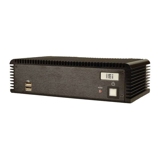
IEI WAFER-8522 Intel Celeron M Fanless Embedded System RoHS Compliant, Dual GbE LAN, COM Ports, USB 2.0
Brand:
IEI Technology
| Category:
Desktop
| Size: 7.38 MB
Table of Contents
Packing List
4
Table of Contents
8
1 Introduction
19
Ecw-281Bb6 Embedded System Overview
20
ECW-281BB6 Benefits
20
ECW-281BB6 Features
20
Figure 1-1: ECW-281BB6 WAFER Series Embedded System
20
Table 1-1: Model Variations
21
Table 1-2: Technical Specifications
22
Power Module Options
23
Power Module Specifications
23
Table 1-3: ECW-281BB6 Power Module Options
23
Power Module Specifications
24
Technical Specifications
21
Ecw-281Bb6 Model Variations
21
Table 1-4: DC-To-DC Power Module Specifications
24
Figure 1-2: Power Adapter
25
Power Adapter
25
Table 1-5: Power Adapter Specifications
26
2 Mechanical Description
27
Ecw-281Bb6 Mechanical Overview
28
Physical Dimensions
28
ECW-281BB6 Dimensions
28
Figure 2-1: ECW-281BB6 Dimensions (MM)
29
Motherboard Dimensions
29
Figure 2-3: Power Module Dimensions (MM)
30
Figure 2-2: WAFER SBC Dimensions (MM)
30
Figure 2-4: ECW-281BB6 Front Panel
31
Bottom Surface
32
Figure 2-5: ECW-281BB6 Rear Panel
32
Figure 2-6: Bottom Surface
33
Internal Overview
33
Power Module Dimensions
30
External Overview
31
Front Panel
31
Rear Panel
31
Figure 2-7: Internal Overview
34
3 System Components
35
Ecw-281Bb6 Embedded System Motherboard
36
Figure 3-1: WAFER-8522 Jumper and Connector Locations
36
WAFER-8522 Motherboard Overview
36
Table 3-1: Supported Processor
37
Table 3-2: Peripheral Interface Connectors
38
AT Power Connector
39
Internal Peripheral Connectors
39
Table 3-3: Rear Panel Connectors
39
ATX Power Connector
40
Table 3-4: at Power Connector Pinouts
40
Audio Connector
41
Peripheral Interface Connectors
38
External Interface Panel Connectors
38
CPU Support
37
Intel ® Celeron ® M
37
Figure 3-2: at Power Connector Location
40
Figure 3-12: WAFER-8522 On-Board External Interface Connectors
51
Figure 3-13: LAN Connector
51
Table 3-15: RJ-45 Ethernet Connector Leds
52
Table 3-16: RS-232 Serial Port (COM 1) Pinouts
52
Figure 3-14: Serial Port Pinout Locations
53
Figure 3-15: VGA Connector
54
Table 3-18: VGA Connector Pinouts
54
Clear CMOS Jumper
55
Figure 3-16: Jumpers
55
Table 3-19: Jumpers
55
WAFER-8522 Motherboard On-Board Jumpers
55
Table 3-21: JP2 Clear CMOS Jumper Settings
56
COM Port Setting Jumper
57
Figure 3-18: JP2 Clear CMOS Jumper
57
Table 3-22: COM Port Setting Jumper Settings
57
Figure 3-19: COM Port Setting Jumper Location
58
LCD Voltage Selection
58
Table 3-23: LCD Voltage Selection Jumper Settings
58
Figure 3-20: LCD Voltage Selection Jumper Location
59
LCD Resolution Selection
59
Connector Mappings
60
Figure 3-21: LCD Resolution Jumper Location
60
Table 3-24: LCD Resolution Jumper Settings
60
ATX Mode Connector
61
Power Connector
61
Table 3-5: ATX Power Connector Pinouts
41
Figure 3-3: ATX Power Connector Location
41
Figure 3-4: Audio Connector Pinouts
42
Figure 3-5: IDE Device Connector Location
43
LED Connector
44
Table 3-7: IDE Connector Pinouts
44
Figure 3-7: Power Button Connector Location
46
Figure 3-8: Reset Button Connector Locations
46
Reset Button Connector
46
Table 3-9: Power Button Connector Pinouts
46
Figure 3-9: Serial Port Connector Location
47
Serial Port Connector (RS-232/422/485)
47
Table 3-10: Reset Button Connector Pinouts
47
Figure 3-10: RS-232 Serial Port Connector Location
48
Serial Port Connector (COM 3, COM 4, COM 5 and COM 6)
48
Table 3-11: RS-232/422/485 Serial Port Connector Pinouts
48
Internal USB Connectors
49
Table 3-12: RS-232 Serial Port Connector Pinouts
49
External Peripheral Interface Connector Overview
50
External Peripheral Interface Connectors
50
Figure 3-11: Internal USB Connector Location
50
Table 3-13: Internal USB Connector Pinouts
50
Ethernet Connector
51
Table 3-14: RJ-45 Ethernet Connector Pinouts
51
Serial Port Connector (COM1)
52
Figure 3-6: LED Connector Locations
45
Power Button Connector
45
Table 3-8: LED Connector Pinouts
45
Table 3-17: USB Connector Pinouts
53
USB Combo Ports
53
VGA Connector
53
IDE Connector
42
Table 3-6: Audio Connector Pinouts
42
Table 3-25: Motherboard Power Connector Mapping
61
Table 3-26: Motherboard Power Connector Mapping
61
4 Installation
63
Anti-Static Precautions
64
Installation Procedure
64
Installation Procedure Overview
64
Unpacking
65
Table 4-1: Package List Contents
66
Bottom Surface Removal
67
Configure the Jumper Settings
67
Figure 4-1: Bottom Surface Retention Screws
67
Figure 4-2: Hard Drive Bracket
68
Figure 4-3:HDD Bracket Retention Screws
68
Figure 4-4: HDD Retention Screws
69
Figure 4-5: HDD Thermal Pad
70
Mounting the System with Mounting Brackets
70
Figure 4-6: Mounting Bracket Retention Screws
71
Mounting the System with Wall Mount Kit
71
Figure 4-7: Wall-Mounting Bracket
72
DIN Mounting
73
Figure 4-8: Mount the Embedded System
73
Figure 4-10: Screw Locations
74
Figure 4-9: DIN Rail Mounting Bracket
74
Cable Connections
75
Figure 4-11: Mounting the DIN RAIL
75
Figure 4-12: Secure the Assembly to the DIN Rail
75
Figure 4-13: Terminal Block Pinouts
76
Power-On Procedure
77
Power -O N Procedure
76
Installation Checklist
76
Terminal Block Pinouts
76
IDE Hard Drive Installation
68
Figure 4-14: Power Button
77
5 Bios Settings
79
Introduction
80
Starting Setup
80
Using Setup
80
Getting Help
81
Unable to Reboot after Configuration Changes
81
BIOS Menu Bar
81
Table 5-1: BIOS Navigation Keys
81
Main
82
Advanced
83
CPU Configuration
84
Menu 3: CPU Configuration
85
IDE Configuration
86
IDE Master, IDE Slave
89
Menu 5: IDE Master and IDE Slave Configuration
90
Super IO Configuration
93
Menu 6: Super IO Configuration
94
Hardware Health Configuration
99
MPS Configuration
100
Trusted Computing
101
USB Configuration
102
USB Mass Storage Device Configuration
104
Boot
106
Boot Settings Configuration
106
BIOS Menu 13: Boot Settings Configuration
107
Boot Device Priority
108
Removable Drives
109
Security
110
Menu 16: Security
111
Chipset
112
Northbridge Configuration
112
Menu 18:Northbridge Chipset Configuration
113
Southbridge Configuration
117
Power Key
118
Menu 20:Power
119
Exit
120
6 Driver Installation
123
Available Software Drivers
124
Chipset Driver Installation
124
Figure 6-1: Installshield Wizard Preparation Screen
124
Figure 6-2: Welcome Screen
125
Figure 6-3: License Agreement
125
Figure 6-4: Readme Information
126
Figure 6-5: Restart the Computer
126
Figure 6-6: Audio Driver Install Shield Wizard Starting
127
Figure 6-7: Audio Driver Setup Preparation
127
Realtek Audio Driver Installation
127
Figure 6-9: Audio Driver Software Configuration
128
Figure 6-8: Audio Driver Welcome Screen
128
Figure 6-12: Audio Driver Installation Complete
130
Figure 6-13: GMA Driver Installation Welcome Screen
131
Figure 6-14: GMA Driver License Agreement
131
Lan Driver Installation
132
Figure 6-11: Audio Driver Installation Begins
129
Figure 6-10: Audio Driver Digital Signal
129
Intel Graphics Media Accelerator Driver
130
Figure 6-15: GMA Driver Installing Notice
132
Figure 6-16: GMA Driver Installation Complete
132
Figure 6-18: Select the Driver Directory
133
Figure 6-17: LAN License Agreement
133
Figure 6-19: LAN Driver Configuration
134
7 Troubleshooting and Maintenance
135
Ecw-281Bb6 System Maintenance Overview
136
System Troubleshooting
136
The System Doesn't Turn on
136
The System Doesn't Boot up
137
More Troubleshooting
138
Component Replacement Procedure
138
SO-DIMM Replacement
139
Figure 7-1: SO-DIMM Cover Plate
139
Figure 7-2: SO-DIMM Removal
140
Figure 7-3: SO-DIMM Thermal Bracket Retention Screws
140
Figure 7-4: SO-DIMM Installation
141
Iei Embedded System Series
143
Iei Embedded
144
Series
144
Overview
144
IEI Embedded System Series
144
IEI Embedded System Series Variations
145
Embedded System Solutions
145
AMD ® Geode
145
LX800 500Mhz Solutions
145
AMD ® Geode
146
GX466 333Mhz Solutions
146
Via ® Luke
146
1Ghz Solutions
146
VIA MARK ® 800Mhz Solutions
147
Intel ® Celeron
147
Intel Pentium M 1.6Ghz Solutions
148
Intel Socket 479 Pentium /Celeron M 2Ghz Solutions
149
LGA 775 Intel
149
D Solutions
149
Intel
149
Socket 479 Core Duo/Solo Solutions
149
Bbios Menu Options
151
Bios Configuration Options
152
Cwatchdog Timer
155
Example Program
157
Daddress Mapping
159
Io Address Map
160
St Mb Memory Address Map
161
Irq Mapping Table
161
Dma Channel Assignments
161
Addres Map
161
Index
163
Advertisement
Advertisement
Related Products
IEI Technology ECW-281B-BTi
IEI Technology ECK-3692
IEI Technology ECN-581A-QM57
IEI Technology ECK-1000 Series
IEI Technology ECK-1000-9453
IEI Technology ECK-1000-690S1
IEI Technology ECN-360A-HM65
IEI Technology ECN-360A-HM65/4G-R10
IEI Technology ECN-360AW-HM65/4G-R10
IEI Technology ECN-780-Q67
IEI Technology Categories
Motherboard
Touch Panel
Computer Hardware
Single board computers
Desktop
More IEI Technology Manuals
Login
Sign In
OR
Sign in with Facebook
Sign in with Google
Upload manual
Upload from disk
Upload from URL