Table of Contents
Advertisement
Quick Links
TANK-700-QM67W-MRAY Em b e d d e d S ys te m
MODEL:
TANK-700-QM67W-MRAY
Hig h P e rfo rm a n c e Fa n le s s Em b e d d e d S ys te m with In te l® 32n m CP U,
On -b o a rd 2.0 GB DDR3 Me m o ry, HDMI, US B 3.0, Gig a b it LAN,
Au d io , 9V~36V DC In p u t, Ro HS Co m p lia n t
Us e r Ma n u a l
P a g e i
Re v. 1.00 – 25 No ve m b e r, 2014
Advertisement
Table of Contents

Related Manuals for IEI Technology TANK-700-QM67W-MRAY


Summary of Contents for IEI Technology TANK-700-QM67W-MRAY
- Page 1 TANK-700-QM67W-MRAY Em b e d d e d S ys te m MODEL: TANK-700-QM67W-MRAY Hig h P e rfo rm a n c e Fa n le s s Em b e d d e d S ys te m with In te l® 32n m CP U, On -b o a rd 2.0 GB DDR3 Me m o ry, HDMI, US B 3.0, Gig a b it LAN,...
- Page 2 TANK-700-QM67W-MRAY Em b e d d e d S ys te m Re vis io n Date Version Changes 25 November, 2014 1.00 Initial release P a g e ii...
- Page 3 TANK-700-QM67W-MRAY Em b e d d e d S ys te m Co p yrig h t COP YRIGHT NOTICE The information in this document is subject to change without prior notice in order to improve reliability, design and function and does not represent a commitment on the part of the manufacturer.
-
Page 4: Table Of Contents
TANK-700-QM67W-MRAY Em b e d d e d S ys te m Ta b le o f Co n te n ts 1 INTRODUCTION ......................1 1.1 O ........................2 VERVIEW 1.2 F ........................2 EATURES 1.3 T ..................3... - Page 5 TANK-700-QM67W-MRAY Em b e d d e d S ys te m 3.7.9 Remote Control Connector (For AT Power Mode Only) ......... 28 3.7.10 RJ-45 RS-232 Serial Ports ................29 3.7.11 RJ-45 RS-422/485 Serial Ports ..............31 3.7.12 RS-232 Serial Port Connectors ..............33 3.7.13 USB Connectors .....................
- Page 6 TANK-700-QM67W-MRAY Em b e d d e d S ys te m 4.3.9 Serial Port Console Redirection ..............65 4.3.10 iEi Feature ...................... 67 4.4 C ........................68 HIPSET 4.4.1 NorthBridge Configuration ................69 4.4.1.1 Graphics Configuration ................69 4.4.2 SouthBridge Configuration ................71 4.4.3 ME Configuration ....................
- Page 7 TANK-700-QM67W-MRAY Em b e d d e d S ys te m Lis t o f Fig u re s Figure 1-1: TANK-700-QM67W-MRAY ................... 2 Figure 1-2: TANK-700-QM67W-MRAY Front Panel ..............5 Figure 1-3: TANK-700-QM67W-MRAY Rear Panel ............... 6 Figure 1-4: TANK-700-QM67W-MRAY LED Indicators ..............7 Figure 1-5: Physical Dimensions (millimeters) ................
- Page 8 TANK-700-QM67W-MRAY Em b e d d e d S ys te m Figure 3-26: Serial Port Pinout Location ..................34 Figure 3-27: USB Device Connection ..................35 Figure 3-28: Power Button ......................36 Figure 3-29: Power Connectors ....................37 Figure 3-30: ACC On: AT Mode ....................38 Figure 3-31: ACC On: ATX Mode ....................38...
- Page 9 TANK-700-QM67W-MRAY Em b e d d e d S ys te m Lis t o f Ta b le s Table 1-1: Technical Specifications ....................4 Table 3-1: DIO Connector Pinouts ....................24 Table 3-2: HDMI Connector Pinouts ...................25 Table 3-3: LAN Pinouts ........................26 Table 3-4: RJ-45 Ethernet Connector LEDs ................27...
-
Page 10: Introduction
TANK-700-QM67W-MRAY Em b e d d e d S ys te m Ch a p te r In tro d u c tio n P a g e 1... -
Page 11: Overview
TANK-700-QM67W-MRAY Em b e d d e d S ys te m 1.1 Ove rvie w Figure 1-1: TANK-700-QM67W-MRAY The TANK-700-QM67W-MRAY Series fanless embedded system is powered by the Intel® Core™ i3-2330E processor and uses the Intel® QM67 chipset. It has one 204-pin DDR3 2 GB SO-DIMM memory and on-board DDR3 2 GB memory. -
Page 12: Technical Specifications
TANK-700-QM67W-MRAY Em b e d d e d S ys te m 1.3 Te c h n ic a l Sp e c ific a tio n s The TANK-700-QM67W-MRAY technical specifications are listed in Table 1-1. S p e c ific a tio n s... -
Page 13: Connector Panel
TANK-700-QM67W-MRAY Em b e d d e d S ys te m S p e c ific a tio n s Exp a n s io n s 2 x Full Size (One Colay mSATA) P CIe Min i P o we r... -
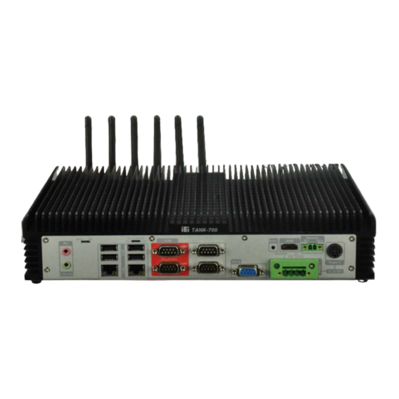
Page 14: Rear Panel
TANK-700-QM67W-MRAY Em b e d d e d S ys te m Figure 1-2: TANK-700-QM67W-MRAY Front Panel 1.4.2 Re a r P a n e l The TANK-700-QM67W-MRAY rear panel contains: 1 x DIO port 1 x 2-pin terminal block for remote control ... -
Page 15: Led Indicators
1.5 LED In d ic a tors There are several indicators on the front panel of the TANK-700-QM67W-MRAY as shown in Figure 1-4. The TANK-700-QM67W-MRAY has no SPF Fiber, CAN bus, so these LED indicators are disabled. P a g e 6... -
Page 16: Figure 1-4: Tank-700-Qm67W-Mray Led Indicators
TANK-700-QM67W-MRAY Em b e d d e d S ys te m Figure 1-4: TANK-700-QM67W-MRAY LED Indicators WARNING: The CPU Temperature Alert LED turns red when the CPU temperature is too high. If this situation occurs, lower the environment temperature or close some running applications to cool down the CPU. -
Page 17: Dimensions
TANK-700-QM67W-MRAY Em b e d d e d S ys te m 1.6 Dim e n s io n s The physical dimensions are shown below: Figure 1-5: Physical Dimensions (millimeters) P a g e 8... -
Page 18: Unpacking
TANK-700-QM67W-MRAY Em b e d d e d S ys te m Ch a p te r Un p a c kin g P a g e 9... -
Page 19: Anti - Static Precautions
TANK-700-QM67W-MRAY Em b e d d e d S ys te m 2.1 An ti-s ta tic P re c a u tio n s WARNING: Failure to take ESD precautions during installation may result in permanent damage to the TANK-700-QM67W-MRAY and severe injury to the user. -
Page 20: Unpacking Checklist
TANK-700-QM67W-MRAY Em b e d d e d S ys te m 2.3 Un pa c kin g Ch e c klis t NOTE: If some of the components listed in the checklist below are missing, please do not proceed with the installation. Contact the IEI reseller or vendor you purchased the TANK-700-QM67W-MRAY from or contact an IEI sales representative directly. - Page 21 TANK-700-QM67W-MRAY Em b e d d e d S ys te m Qu a n tity Ite m a n d P a rt Nu m b e r Im a g e S ta n d a rd RJ-45 to DB-9 COM port cable...
-
Page 22: Installation
TANK-700-QM67W-MRAY Em b e d d e d S ys te m Ch a p te r In s ta lla tio n P a g e 13... -
Page 23: Installation Precautions
TANK-700-QM67W-MRAY Em b e d d e d S ys te m 3.1 In s ta lla tio n P re c a u tio n s During installation, be aware of the precautions below: Read the user manual: The user manual provides a complete description of the TANK-700-QM67W-MRAY, installation instructions and configuration options. -
Page 24: Figure 3-1: Bottom Panel Retention Screws
TANK-700-QM67W-MRAY Em b e d d e d S ys te m Figure 3-1: Bottom Panel Retention Screws S te p 2: Remove the four HDD bracket retention screws and unplug the SATA signal and power cables connected to the TANK-700-QM67W-MRAY. And then lift the HDD bracket out of the TANK-700-QM67W-MRAY and put it on a flat surface. -
Page 25: Figure 3-3: Hdd Installation
TANK-700-QM67W-MRAY Em b e d d e d S ys te m S te p 3: Attach the HDD to the HDD bracket, and then slide the HDD to connect the SATA connector. Figure 3-3: HDD Installation Secure the HDD with the HDD bracket by four retention screws. -
Page 26: Pluggable Dc-I N Terminal Block Installation
TANK-700-QM67W-MRAY Em b e d d e d S ys te m S te p 7: Reinstall the bottom panel to the TANK-700-QM67W-MRAY. 3.3 P lu g g a b le DC-In Te rm in a l Blo c k In s ta lla tio n... -
Page 27: Figure 3-6: Pluggable Remote Control Terminal Block Installation
TANK-700-QM67W-MRAY Em b e d d e d S ys te m S te p 2: Align the pluggable remote control terminal block with the remote control terminal block connector on the TANK-700-QM67W-MRAY. Once aligned, insert the pluggable remote control terminal block into the remote S te p 3: control terminal block connector. -
Page 28: So-Dimm Installation
TANK-700-QM67W-MRAY Em b e d d e d S ys te m 3.5 S O-DIMM In s ta lla tio n WARNING: Using incorrectly specified SO-DIMM may cause permanently damage the TANK-700-QM67W-MRAY. Please make sure the purchased SO-DIMM complies with... -
Page 29: Mounting The System With Mounting Brackets
TANK-700-QM67W-MRAY Em b e d d e d S ys te m Push the SO-DIMM into the socket at an angle (Figure 3-8). S te p 5: Figure 3-8: SO-DIMM Installation S te p 6: Gently pull the arms of the SO-DIMM socket out and push the rear of the SO-DIMM down (Figure 3-8). -
Page 30: External Peripheral Interface Connectors
TANK-700-QM67W-MRAY Em b e d d e d S ys te m Figure 3-9: Mounting Bracket Retention Screws S te p 3: Secure the brackets to the system by inserting two retention screws into each bracket (Figure 3-9). Drill holes in the intended installation surface. -
Page 31: Acc Mode Selection
Wireless antenna 3.7.1 ACC Mo d e S e le c tio n The TANK-700-QM67W-MRAY allows turning the ACC mode on or off. The setting can be made through the ACC mode switch on the rear panel as shown below. -
Page 32: Audio Connector
TANK-700-QM67W-MRAY Em b e d d e d S ys te m Figure 3-11: AT/ATX Power Mode Switch 3.7.3 Au d io Co n n e c to r CN La b e l: Lin e o u t and Mic... -
Page 33: Hdmi Connector
TANK-700-QM67W-MRAY Em b e d d e d S ys te m CN Lo c a tio n : See Figure 1-3 CN P in o u ts : See Table 3-1 and Figure 3-13 The digital I/O connector provides programmable input and output for external devices. -
Page 34: Lan Connectors
TANK-700-QM67W-MRAY Em b e d d e d S ys te m Description Description HDMI_DATA1# HDMI_DATA0 HDMI_DATA0# HDMI_CLK HDMI_CLK# HDMI_SCL HDMI_SDA HDMI_HPD HDMI_GND HDMI_GND HDMI_GND HDMI_GND Table 3-2: HDMI Connector Pinouts 3.7.6 LAN Co n n e c to rs... -
Page 35: Figure 3-14: Lan Connection
TANK-700-QM67W-MRAY Em b e d d e d S ys te m Figure 3-14: LAN Connection Insert the LAN cable RJ-45 connector. Once aligned, gently insert the LAN S te p 3: cable RJ-45 connector into the on-board RJ-45 connector. -
Page 36: Power Input, 4-Pin Terminal Block
TANK-700-QM67W-MRAY Em b e d d e d S ys te m Activity/Link LED Speed LED DESCRIPTION STATUS DESCRIPTION STATUS No link 10 Mbps connection Yellow Linked Green 100 Mbps connection Blinking TX/RX activity Orange 1 Gbps connection Table 3-4: RJ-45 Ethernet Connector LEDs 3.7.7 P owe r In p u t, 4-p in Te rm in a l Blo c k... -
Page 37: Remote Control Connector (For At Power Mode Only)
TANK-700-QM67W-MRAY Em b e d d e d S ys te m The power connector connects to the 10.5V~36V DC power adapter. Figure 3-17: Power Input Connector Description Description +12V +12V Table 3-6: Power Input Pinouts 3.7.9 Re m o te Co n tro l Co n n e c to r (Fo r AT P o we r Mo d e On ly) -
Page 38: Rs-232 Serial Ports
TANK-700-QM67W-MRAY Em b e d d e d S ys te m 3.7.10 RJ -45 RS -232 S e ria l P o rts RS 232 CN La b e l: RJ-45 CN Typ e : CN Lo c a tio n :... -
Page 39: Figure 3-20: Rj-45 Rs-232 Serial Port Pinout Location
TANK-700-QM67W-MRAY Em b e d d e d S ys te m Secure the connector. Secure the serial device connector to the external S te p 4: interface by tightening the two retention screws on either side of the connector. -
Page 40: Rs-422/485 Serial Ports
TANK-700-QM67W-MRAY Em b e d d e d S ys te m 3.7.11 RJ -45 RS -422/485 S e ria l P o rts RS 422/485 CN La b e l: RJ-45 CN Typ e : CN Lo c a tio n :... -
Page 41: Figure 3-23: Rj-45 Rs-422/485 Serial Port Pinout Location
TANK-700-QM67W-MRAY Em b e d d e d S ys te m Secure the connector. Secure the serial device connector to the external S te p 4: interface by tightening the two retention screws on either side of the connector. -
Page 42: Rs-232 Serial Port Connectors
TANK-700-QM67W-MRAY Em b e d d e d S ys te m Table 3-10: DB-9 Connector Pinouts 3.7.12 RS -232 S e ria l P o rt Co n n e c to rs CN La b e l: COM1, COM2, COM3 and COM4... -
Page 43: Usb Connectors
TANK-700-QM67W-MRAY Em b e d d e d S ys te m Secure the connector. Secure the serial device connector to the external S te p 3: interface by tightening the two retention screws on either side of the connector. -
Page 44: Powering O N /Off The System
TANK-700-QM67W-MRAY Em b e d d e d S ys te m Figure 3-27: USB Device Connection Insert the device connector. Once aligned, gently insert the USB device S te p 3: connector into the on-board connector. Description Description DATA-... -
Page 45: Redundant Power
TANK-700-QM67W-MRAY Em b e d d e d S ys te m Power off the system: press the power button for 6 seconds Figure 3-28: Power Button 3.9 Re d u n d a n t P owe r The TANK-700-QM67W-MRAY is a system that supports redundant power. -
Page 46: Acc On
When TANK-700-QM67W-MRAY is in ACC On mode, the main power input is the Power 1 connector and the backup power is from the Power 2 connector. 3.9.1.1 Bo o t-u p When both power connectors are connected to a power source with over 9 V, the two... -
Page 47: Switch To Backup Power
TANK-700-QM67W-MRAY Em b e d d e d S ys te m high. The user can choose AT power mode or ATX power mode to control the system. The following flow diagrams show the boot-up process and the LED status in AT and ATX power modes. -
Page 48: Shutdown
Press the Power button for six seconds to turn off the system. 3.9.2 ACC OFF When the TANK-700-QM67W-MRAY is in ACC Off mode, the main power input is the Power 2 connector and the backup power is from the Power 1 connector. 3.9.2.1 Bo o t-u p When both power connectors are connected to a power source with over 9 V, the two power LEDs on the front panel turn on. -
Page 49: Switch To Backup Power
TANK-700-QM67W-MRAY Em b e d d e d S ys te m power mode to control the system. The following flow diagrams show the boot-up process and the LED status in AT and ATX power modes. Figure 3-34: ACC Off: AT Mode Figure 3-35: ACC Off: ATX Mode 3.9.2.2 S witc h to Ba c ku p P owe r... -
Page 50: Shutdown
TANK-700-QM67W-MRAY Em b e d d e d S ys te m NOTE: System power can switch between Power 2 and Power 1 automatically when a 12 V power adapter is being connected to Power 2 and the power input of Power 1 is from 9 V to 16 V. If Power 2 is unplugged and the power input of Power 1 is over 16 V, system power will switch to Power 1 automatically. - Page 51 TANK-700-QM67W-MRAY Em b e d d e d S ys te m NOTE: The power LED turns off when the power cable is unplugged from the system. P a g e 42...
-
Page 52: Bios
TANK-700-QM67W-MRAY Em b e d d e d S ys te m Ch a p te r BIOS P a g e 43... -
Page 53: Introduction
TANK-700-QM67W-MRAY Em b e d d e d S ys te m 4.1 In tro d u c tio n The BIOS is programmed onto the BIOS chip. The BIOS setup program allows changes to certain system settings. This chapter outlines the options that can be changed. -
Page 54: Getting Help
TANK-700-QM67W-MRAY Em b e d d e d S ys te m Ke y Fu n c tio n Esc key Main Menu – Quit and not save changes into CMOS Status Page Setup Menu and Option Page Setup Menu --... -
Page 55: Main
TANK-700-QM67W-MRAY Em b e d d e d S ys te m 4.2 Ma in The Main BIOS menu (BIOS Menu 1) appears when the BIOS Setup program is entered. The Main menu gives an overview of the basic system information. -
Page 56: Advanced
TANK-700-QM67W-MRAY Em b e d d e d S ys te m S ys te m Tim e [xx:xx:xx] Use the System Time option to set the system time. Manually enter the hours, minutes and seconds. 4.3 Ad va n c e d... -
Page 57: Acpi Settings
TANK-700-QM67W-MRAY Em b e d d e d S ys te m 4.3.1 ACP I S e ttin g s The ACPI Settings menu (BIOS Menu 3) configures the Advanced Configuration and Power Interface (ACPI) options. Aptio Setup Utility – Copyright (C) 2010 American Megatrends, Inc. -
Page 58: Trusted Computing
TANK-700-QM67W-MRAY Em b e d d e d S ys te m 4.3.2 Tru s te d Co m p u tin g Use the Trusted Computing menu (BIOS Menu 4) to configure settings related to the Trusted Computing Group (TCG) Trusted Platform Module (TPM). -
Page 59: Cpu Configuration
TANK-700-QM67W-MRAY Em b e d d e d S ys te m 4.3.3 CP U Co n fig u ra tio n Use the CPU Configuration menu (BIOS Menu 5) to view detailed CPU specifications and configure the CPU. Aptio Setup Utility – Copyright (C) 2010 American Megatrends, Inc. -
Page 60: Sata Configuration
TANK-700-QM67W-MRAY Em b e d d e d S ys te m Hyp e r-th re a d in g [En a b le d ] Use the Hyper-threading function to enable or disable the CPU hyper threading function. -
Page 61: Usb Configuration
TANK-700-QM67W-MRAY Em b e d d e d S ys te m S ATA Co n tro lle r(s ) [En a b le d ] Use the SATA Controller(s) option to enable or disable the SATA controller. ... - Page 62 TANK-700-QM67W-MRAY Em b e d d e d S ys te m US B2.0 S u p p o rt [En a b le d ] Use the USB2.0 Support option to enable or disable USB 2.0 support on the system.
-
Page 63: Second Super Io Configuration
TANK-700-QM67W-MRAY Em b e d d e d S ys te m 4.3.6 S e c o n d S u pe r IO Co nfig u ra tio n Use the F81216 Second Super IO Configuration menu (BIOS Menu 8) to set or change the configurations for the serial ports. - Page 64 TANK-700-QM67W-MRAY Em b e d d e d S ys te m 4.3.6.1.1 S e ria l P o rt 7 Co n fig u ra tio n S e ria l P o rt [En a b le d ] Use the Serial Port option to enable or disable the serial port.
- Page 65 TANK-700-QM67W-MRAY Em b e d d e d S ys te m De vic e Mo d e [No rm a l] Use the Device Mode option to enable or disable the serial port. Sets the serial port mode to normal.
-
Page 66: Super Io Configuration
TANK-700-QM67W-MRAY Em b e d d e d S ys te m Serial Port I/O port address is 3E8h and the interrupt IO=3E8h; IRQ=3, 4, 5, address is IRQ3, 4, 5, 6, 7, 9, 10, 11, 12 6, 7, 9, 10, 11, 12 ... -
Page 67: Serial Port N Configuration
TANK-700-QM67W-MRAY Em b e d d e d S ys te m 4.3.7.1 S e ria l P o rt n Co n fig u ra tio n Use the Serial Port n Configuration menu (BIOS Menu 11) to configure the serial port n. - Page 68 TANK-700-QM67W-MRAY Em b e d d e d S ys te m Serial Port I/O port address is 3F8h and the interrupt IO=3F8h; IRQ=3, 4 address is IRQ3, 4 IO=2F8h; Serial Port I/O port address is 2F8h and the interrupt...
- Page 69 TANK-700-QM67W-MRAY Em b e d d e d S ys te m Serial Port I/O port address is 2C8h and the interrupt IO=2C8h; IRQ=3, 4 address is IRQ3, 4 4.3.7.1.3 S e ria l P o rt 3 Co n fig u ra tio n ...
- Page 70 TANK-700-QM67W-MRAY Em b e d d e d S ys te m 4.3.7.1.4 S e ria l P o rt 4 Co n fig u ra tio n S e ria l P o rt [En a b le d ] Use the Serial Port option to enable or disable the serial port.
- Page 71 TANK-700-QM67W-MRAY Em b e d d e d S ys te m Ch a n g e S e ttin g s [Au to ] Use the Change Settings option to change the serial port IO port address and interrupt address.
- Page 72 TANK-700-QM67W-MRAY Em b e d d e d S ys te m The serial port IO port address and interrupt address Auto EFAULT are automatically detected. IO=2E0h; Serial Port I/O port address is 2E0h and the interrupt address is IRQ10 IRQ=10 ...
-
Page 73: H/W Monitor
TANK-700-QM67W-MRAY Em b e d d e d S ys te m 4.3.8 H/W Mo n ito r The H/W Monitor menu (BIOS Menu 12) shows the operating temperature, fan speeds and system voltages. Aptio Setup Utility – Copyright (C) 2010 American Megatrends, Inc. -
Page 74: Serial Port Console Redirection
TANK-700-QM67W-MRAY Em b e d d e d S ys te m 4.3.9 S e ria l P o rt Co n s o le Re d ire c tio n The Serial Port Console Redirection menu (BIOS Menu 13) allows the console redirection options to be configured. - Page 75 TANK-700-QM67W-MRAY Em b e d d e d S ys te m Disabled the console redirection function Disabled EFAULT Enabled Enabled the console redirection function Te rm in a l Typ e [VT100+] Use the Terminal Type option to specify the remote terminal type.
-
Page 76: Iei Feature
TANK-700-QM67W-MRAY Em b e d d e d S ys te m 4.3.10 iEi Fe a tu re Use the iEi Feature menu (BIOS Menu 14) to configure the iEi features. Aptio Setup Utility – Copyright (C) 2010 American Megatrends, Inc. -
Page 77: Chipset
TANK-700-QM67W-MRAY Em b e d d e d S ys te m 4.4 Ch ips e t Use the Chipset menu (BIOS Menu 15) to access the Northbridge and Southbridge configuration menus. WARNING! Setting the wrong values for the Chipset BIOS selections in the Chipset BIOS menu may cause the system to malfunction. -
Page 78: Northbridge Configuration
TANK-700-QM67W-MRAY Em b e d d e d S ys te m 4.4.1 No rth Brid g e Co n fig u ra tio n Use the NorthBridge Configuration menu (BIOS Menu 16) to configure the Northbridge chipset. Aptio Setup Utility – Copyright (C) 2010 American Megatrends, Inc. - Page 79 TANK-700-QM67W-MRAY Em b e d d e d S ys te m DVMT P re -Allo c a te d [64 M] Use the DVMT Pre-Allocated option to specify the amount of system memory that can be used by the Internal Graphics Device.
-
Page 80: Southbridge Configuration
TANK-700-QM67W-MRAY Em b e d d e d S ys te m 480 MB of memory used by internal graphics 480 M device 512 M 512 MB of memory used by internal graphics device DVMT To ta l Gfx Me m [MAX] Use the DVMT Total Gfx Mem option to select the amount of DVMT5.0 total memory... - Page 81 TANK-700-QM67W-MRAY Em b e d d e d S ys te m Aptio Setup Utility – Copyright (C) 2010 American Megatrends, Inc. Chipset SouthBridge Configuration Enabled or Disabled USB Controller Auto Power Button Status [ON] USB Controller [Enabled] --------------------- : Select Screen USB 3.0 Controller...
- Page 82 TANK-700-QM67W-MRAY Em b e d d e d S ys te m Wa ke o n Gb E LAN [Dis a b le d ] Use the Wake on GbE LAN option to enable or disable resuming from GbE LAN controller.
-
Page 83: Me Configuration
TANK-700-QM67W-MRAY Em b e d d e d S ys te m P o we r S a vin g Fu n c tio n [Dis a b le d ] Use the Power Saving Function BIOS option to enable or disable the power saving function. -
Page 84: Boot
TANK-700-QM67W-MRAY Em b e d d e d S ys te m Un -Co n fig u re ME [Dis a b le d ] Use the Un-Configure ME option to perform ME un-configure without password operation. Disabled... -
Page 85: Security
TANK-700-QM67W-MRAY Em b e d d e d S ys te m Does not enable the keyboard Number Lock automatically. To use the 10-keys on the keyboard, press the Number Lock key located on the upper left-hand corner of the 10-key pad. The Number Lock LED on the keyboard lights up when the Number Lock is engaged. -
Page 86: Exit
TANK-700-QM67W-MRAY Em b e d d e d S ys te m Us e r P a s s wo rd Use the User Password to set or change a user password. 4.7 Exit Use the Exit menu (BIOS Menu 22) to load default BIOS values, optimal failsafe values and to save configuration changes. - Page 87 TANK-700-QM67W-MRAY Em b e d d e d S ys te m S a ve a s Us e r De fa u lts Use the Save as User Defaults option to save the changes done so far as user defaults.
-
Page 88: A Safety Precautions
TANK-700-QM67W-MRAY Em b e d d e d S ys te m Ap p e n d ix S a fe ty P re c a u tio n s P a g e 79... -
Page 89: Safety Precautions
TANK-700-QM67W-MRAY Em b e d d e d S ys te m A.1 S a fe ty P re c a u tio n s WARNING: The precautions outlined in this appendix should be strictly followed. Failure to follow these precautions may result in permanent damage to the TANK-700-QM67W-MRAY. -
Page 90: Anti-Static Precautions
Electrostatic discharge (ESD) can cause serious damage to electronic components, including the TANK-700-QM67W-MRAY. Dry climates are especially susceptible to ESD. It is therefore critical that whenever the TANK-700-QM67W-MRAY is opened and any of the electrical components are handled, the following anti-static precautions are strictly adhered to. -
Page 91: Product Disposal
When maintaining or cleaning the TANK-700-QM67W-MRAY, please follow the guidelines below. A.2.1 Ma in te n a n c e a n d Cle a n in g Prior to cleaning any part or component of the TANK-700-QM67W-MRAY, please read the details below. P a g e 82... -
Page 92: Cleaning Tools
TANK-700-QM67W-MRAY Em b e d d e d S ys te m The interior of the TANK-700-QM67W-MRAY does not require cleaning. Keep fluids away from the TANK-700-QM67W-MRAY interior. Be cautious of all small removable components when vacuuming the TANK-700-QM67W-MRAY. -
Page 93: B Hazardous Materials Disclosure
TANK-700-QM67W-MRAY Em b e d d e d S ys te m Ap p e n d ix Ha za rd o u s Ma te ria ls Dis c lo s u re P a g e 84... -
Page 94: Hazardous Materials Disclosure Table For Ipb Products Certified As R Ohs Compliant Under 2002/95/Ec Without Mercury
TANK-700-QM67W-MRAY Em b e d d e d S ys te m B.1 Ha za rd o u s Ma te ria ls Dis c lo s u re Ta ble for IP B P ro d u c ts... - Page 95 TANK-700-QM67W-MRAY Em b e d d e d S ys te m P a rt Na m e To xic o r Ha za rd o u s S u b s ta n c e s a n d Ele m e n ts...
- Page 96 TANK-700-QM67W-MRAY Em b e d d e d S ys te m 此附件旨在确保本产品符合中国 RoHS 标准。以下表格标示此产品中某有毒物质的含量符 合中国 RoHS 标准规定的限量要求。 本产品上会附有”环境友好使用期限”的标签,此期限是估算这些物质”不会有泄漏或突变”的 年限。本 产品可能包含有较短的环境友好使用期限的可替换元件,像是电池或灯管,这些元 件将会单独标示出来。 部件名称 有毒有害物质或元素 铅 汞 镉 六价铬 多溴联苯 多溴二苯 醚 (P b ) (Hg ) (Cd ) (CR(VI)) (P BB) (P BDE) 壳体...
Need help?
Do you have a question about the TANK-700-QM67W-MRAY and is the answer not in the manual?
Questions and answers