Table of Contents

Subscribe to Our Youtube Channel
Related Manuals for Transition Networks SI-IES-111D-LRT


Summary of Contents for Transition Networks SI-IES-111D-LRT
-
Page 1: User Guide
Transition Networks SI-IES-111D-LRT and -121D-LRT User Guide SI-IES-111D-LRT and SI-IES-121D-LRT Hardened PoE/PoE+ Injector / Converter User Guide PN 33585 Rev. G Ver 1.02 February 2017 33585 Rev. G https://www.transition.com/ Page 1 of 25... -
Page 2: Table Of Contents
Transition Networks SI-IES-111D-LRT and -121D-LRT User Guide Contents 1. Overview ........................5 Introduction ........................5 Features ........................6 Packing List ........................6 Safety Precaution ......................6 2. Hardware Description ....................7 Front Panel ........................7 Top View ........................8 Grounding ........................8 Wiring the Power Inputs .................... -
Page 3: Fcc Warning
Transition Networks SI-IES-111D-LRT and -121D-LRT User Guide FCC Warning This Equipment has been tested and found to comply with the limits for a Class-A digital device, pursuant to Part 15 of the FCC rules. These limits are designed to provide reasonable protection against harmful interference in a residential installation. -
Page 4: Contact Information
Copyright Notice/Restrictions © Copyright 2013-2017 Transition Networks. All rights reserved. No part of this work may be reproduced or used in any form or by any means (graphic, electronic or mechanical) without written permission from Transition Networks. Printed in the U.S.A. -
Page 5: Overview
SI-IES-111D-LRT SI-IES-111D-LRT has one SFP slot and one RJ45 port. The RJ45 port supports IEEE 802.3af (PoE) and 802.3at (PoE+), and can provide up to 30W for high powered application. The SFP slot provides more flexibility when planning and implementing the network. -
Page 6: Features
LED is for the Gigabit transmission. There are also LEDs for PoE activity and input power. Features SI-IES-111D-LRT provides 1 x SFP Dual-Speed slot + 1 x RJ45 with IEEE 802.3af/IEEE 802.3at PSE injector function SI-IES-121D-LRT provides 1 x SFP Dual-Speed slot + 2 x RJ45 with IEEE 802.3af/IEEE 802.3at PSE injector function... -
Page 7: Hardware Description
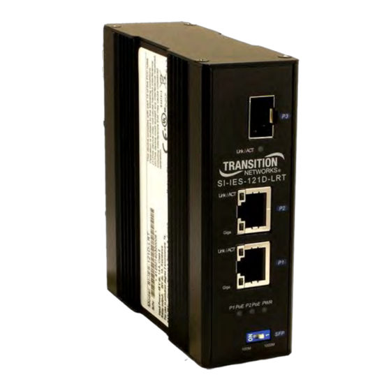
2. Hardware Description This section introduces device hardware specifications, port configurations, cabling information, and installation wiring. Front Panel The SI-IES-111D-LRT and SI-IES-121D-LRT front panels are shown below. Hardened PoE+ Devices Front Panels 33585 Rev. G https://www.transition.com/ Page 7 of 24... -
Page 8: Top View
Transition Networks SI-IES-111D-LRT and -121D-LRT User Guide Top View Consistent with the IP31 rating, the terminal block connector for the DC power input is located on the bottom of the device. Top panel of the Hardened PoE+ Devices Grounding Required:... -
Page 9: Wiring The Power Inputs
Transition Networks SI-IES-111D-LRT and -121D-LRT User Guide Wiring the Power Inputs Follow the steps below to insert the power wire. 1. Locate the labeling on the device indicating the location of V+ and V- power input connections on the device. -
Page 10: Led Indicators
Transition Networks SI-IES-111D-LRT and -121D-LRT User Guide LED Indicators There are LEDs located on the front panel of the Hardened PoE injector to display the power status and network status. Each LED state and color has its own specific meaning as defined in the table below. -
Page 11: Ports
Transition Networks SI-IES-111D-LRT and -121D-LRT User Guide The SFPs are hot-swappable. However, you must cycle device power whenever the DIP switch is changed (i.e., whenever changing SFP mode/speed). Ports RJ45 ports (Auto MDI/MDIX): The RJ-45 ports are auto-sensing for 10Base-T, 100Base-TX or 1000Base-T device connections. -
Page 12: Cabling
Transition Networks SI-IES-111D-LRT and -121D-LRT User Guide Signals for 1000Base-T Signal name Signal definition TRD+(0) Transmit and receive data 0 (positive lead) TRD-(0) Transmit and receive data 0 (negative lead) TRD+(1) Transmit and receive data 1 (positive lead) TRD+(2) Transmit and receive data 2 (positive lead) - Page 13 Transition Networks SI-IES-111D-LRT and -121D-LRT User Guide To connect the transceiver and LC cable, follow the steps shown below: 1. Insert the transceiver into the SFP module. Notice that the triangle mark is the bottom of the module. Figure 2.8: Transceiver to the SFP module Figure 2.9: Transceiver Inserted...
- Page 14 Transition Networks SI-IES-111D-LRT and -121D-LRT User Guide To remove the LC connector from the transceiver, follow the steps below: 1. Press the upper side of the LC connector from the transceiver and pull it out to release. Figure 2.11: Remove LC connector 2.
-
Page 15: Mounting Installation
Transition Networks SI-IES-111D-LRT and -121D-LRT User Guide 3. Mounting Installation DIN-Rail Mounting The DIN-rail clip is screwed onto the Hardened PoE Injector/Converter when manufactured at the factory. If the DIN-rail clip is not installed, see the following figure to screw install the DIN-rail clip onto the switch. - Page 16 Transition Networks SI-IES-111D-LRT and -121D-LRT User Guide Follow the steps below to hang the Hardened PoE injector on the DIN-rail track. 1. Insert the top of DIN-rail clip over the top edge of the DIN-rail track. 2. Lightly push down on the Hardened PoE Injector/Converter until the bottom of DIN-rail clip snaps onto the bottom edge of the DIN-rail track.
-
Page 17: Wall Mount Plate Mounting (Optional)
Transition Networks SI-IES-111D-LRT and -121D-LRT User Guide Wall Mount Plate Mounting (Optional) Follow the steps below to mount the Hardened PoE Injector/Converter with wall mount plate. Remove the DIN-rail clip from the Hardened PoE Injector/Converter by removing the three mounting screws as shown below. -
Page 18: Troubleshooting
Transition Networks SI-IES-111D-LRT and -121D-LRT User Guide 4. Troubleshooting □ Select the proper UTP cable to construct your network. Check that you are using the right cable. Use unshielded twisted-pair (UTP) or shield twisted-pair (STP) cable for RJ45 connections: 100Ω Category 3, 4 or 5 cable for 10Mbps connections, 100Ω Category 5 cable for 100Mbps, or 100Ω... -
Page 19: Technical Specifications
Transition Networks SI-IES-111D-LRT and -121D-LRT User Guide 5. Technical Specifications SI-IES-1x1D-LRT Specifications The technical specifications of the Hardened PoE Injector/Converter are listed below. Note that specifications are subject to change without further notification Communications IEEE 802.3, 802.3ab, 802.3u, 802.3x, 802.3z, 802.3af, and 802.3at. - Page 20 Transition Networks SI-IES-111D-LRT and -121D-LRT User Guide Physical Features 36.7mm x 94.5mm x 108.4mm Dimensions (WxDxH) IP31, Metal shell with solid mounting kits Enclosure DIN-rail, Wall-mount (optional) Mounting Environment -40 ~ 75 Operating Temperature -40 ~ 85 Storage Temperature 5 ~ 95% (non-condensing)
-
Page 21: Power Supply Specifications
Transition Networks SI-IES-111D-LRT and -121D-LRT User Guide Power Supply Specifications Power supply option TN PN 25131 specs are provided below (subject to change). 25131 Features and Specifications The 25131 power supply is a 48VDC, 75 Watts, Industrial DIN-rail Mounted Power Supply. -
Page 22: Service
This warranty is your only remedy. No other warranties, such as fitness for a particular purpose, are expressed or implied. Transition Networks is not liable for any special, indirect, incidental or consequential damages or losses, including loss of data, arising from any cause or theory. - Page 23 Transition Networks reserves the right to charge a $50 fee for all testing and shipping incurred, if after testing, a return is classified as “No Problem Found.”...
-
Page 24: Declaration Of Conformity
Transition Networks SI-IES-111D-LRT and -121D-LRT User Guide Declaration of Conformity 33585 Rev. G https://www.transition.com/ Page 24 of 24... - Page 25 10900 Red Circle Drive Minnetonka, MN 55343 USA Tel: 952- 941-7600 or 1-800-526-9267 Fax: 952-941-2322 Copyright© 2013-2017 Transition Networks. All rights reserved. SI-IES-111D-LRT and SI-IES-121D-LRT Hardened PoE/PoE+ Media Converter User Guide PN 33585 Rev. G 33585 Rev. G https://www.transition.com/ Page 25 of 24...
Need help?
Do you have a question about the SI-IES-111D-LRT and is the answer not in the manual?
Questions and answers