
Related Manuals for Transition Networks SI-IES-111D-LRT


Summary of Contents for Transition Networks SI-IES-111D-LRT
- Page 1 Transition Networks SI-IES-111D-LRT and -121D-LRT User Guide SI-IES-111D-LRT and SI-IES-121D-LRT Unmanaged Hardened PoE+ Injector/Converter User Guide PN 33585 Rev. J 33585 Rev. J https://www.transition.com/ Page 1 of 27...
-
Page 2: Table Of Contents
Transition Networks SI-IES-111D-LRT and -121D-LRT User Guide Contents 1. Overview ..........................5 Introduction ........................... 5 Ordering Information ......................5 Features ..........................5 Packing List ........................... 6 Safety Precaution ........................6 Product Views ........................6 2. Hardware Description ......................7 Front Panel..........................7 Top View .......................... - Page 3 Transition Networks SI-IES-111D-LRT and -121D-LRT User Guide FCC Warning This Equipment has been tested and found to comply with the limits for a Class-A digital device, pursuant to Part 15 of the FCC rules. These limits are designed to provide reasonable protection against harmful interference in a residential installation.
- Page 4 Copyright Notice/Restrictions Copyright © 2013-2020 Transition Networks. All rights reserved. No part of this work may be reproduced or used in any form or by any means (graphic, electronic or mechanical) without written permission from Transition Networks. Printed in the U.S.A.
-
Page 5: Overview
1. Overview Introduction The SI-IES-111D-LRT is a 2-port unmanaged hardened PoE+ injector that adds up to 30 Watts of power from its PoE+ Port onto a network segment. The gigabit speed SFP slot provides the ultimate flexibility by allowing fiber SFP uplink ports with varying communication distances. -
Page 6: Packing List
Transition Networks SI-IES-111D-LRT and -121D-LRT User Guide Packing List • One Hardened Injector/ Converter with IEEE 802.3af/IEEE 802.3at PSE • One Documentation Postcard • One DIN-rail Clip • Two Wall Mounting Brackets and Screws (Optional) Safety Precaution If DC voltage is supplied by an external power supply; you must use an isolated power supply. -
Page 7: Hardware Description
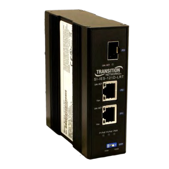
2. Hardware Description This section provides product views, grounding, wiring, LED, DIP switch, and cabling information. Front Panel The SI-IES-111D-LRT and SI-IES-121D-LRT front panels are shown below. Hardened PoE+ Devices Front Panels Top View Consistent with the IP31 rating, the terminal block connector for the DC power input is located on the bottom of the device. -
Page 8: Grounding
Transition Networks SI-IES-111D-LRT and -121D-LRT User Guide Grounding After the Switch is mounted and connected, the front panel grounding screw can be used for grounding. Grounding and wire routing help limit the effects of noise due to electromagnetic interference (EMI). Run the ground connection from the ground screw to the grounding surface before connecting devices. -
Page 9: Ports
Transition Networks SI-IES-111D-LRT and -121D-LRT User Guide Ports RJ45 ports (Auto MDI/MDIX): The RJ-45 ports are auto-sensing for 10Base-T, 100Base-TX or 1000Base-T device connections. Auto MDI/MDIX means that you can connect to another switch or workstation without changing straight through or crossover cabling. See information below for straight through and crossover cable PIN assignments. -
Page 10: Cabling
Transition Networks SI-IES-111D-LRT and -121D-LRT User Guide Signals for 1000Base-T Signal name Signal definition TRD+(0) Transmit and receive data 0 (positive lead) TRD-(0) Transmit and receive data 0 (negative lead) TRD+(1) Transmit and receive data 1 (positive lead) TRD+(2) Transmit and receive data 2 (positive lead) - Page 11 Transition Networks SI-IES-111D-LRT and -121D-LRT User Guide To connect the SFP transceiver and LC cable, follow the steps shown below: 1. Insert the transceiver into the SFP module. Notice that the triangle mark is the bottom of the module. Figure 2.8: Transceiver to the SFP module Figure 2.9: Transceiver Inserted...
- Page 12 Transition Networks SI-IES-111D-LRT and -121D-LRT User Guide To remove the LC connector from the SFP transceiver, follow the steps below: 1. Press the upper side of the LC connector from the transceiver and pull it out to release. Figure 2.11: Remove LC connector 2.
-
Page 13: Wiring The Power Inputs
Transition Networks SI-IES-111D-LRT and -121D-LRT User Guide Wiring the Power Inputs Follow the steps below to insert the power wire. 1. Locate the labeling on the device indicating the location of V+ and V- power input connections on the device. -
Page 14: Led Indicators
Transition Networks SI-IES-111D-LRT and -121D-LRT User Guide LED Indicators The front panel LEDs display power status and network status. Each LED state and color has its own specific meaning as defined in the table below. Table 2.1: LED Definition LED Indicator... -
Page 15: Mounting
Transition Networks SI-IES-111D-LRT and -121D-LRT User Guide 3. Mounting DIN-Rail Mounting The DIN-rail clip is screwed onto the Hardened PoE Injector/Converter when manufactured at the factory. If the DIN-rail clip is not installed, see the following figure to screw install the DIN-rail clip onto the switch. - Page 16 Transition Networks SI-IES-111D-LRT and -121D-LRT User Guide Follow the steps below to hang the Hardened PoE injector on the DIN-rail track. 1. Insert the top of DIN-rail clip over the top edge of the DIN-rail track. 2. Lightly push down on the Hardened PoE Injector/Converter until the bottom of DIN-rail clip snaps onto the bottom edge of the DIN-rail track.
-
Page 17: Wall Mount Plate Mounting (Optional)
Transition Networks SI-IES-111D-LRT and -121D-LRT User Guide Wall Mount Plate Mounting (Optional) Follow the steps below to mount the Hardened PoE Injector/Converter with wall mount plate. 1. Remove the DIN-rail clip from the Hardened PoE Injector/Converter by removing the three mounting screws as shown below. -
Page 18: Troubleshooting
Transition Networks SI-IES-111D-LRT and -121D-LRT User Guide 4. Troubleshooting □ Select the proper UTP cable to construct your network. Use unshielded twisted-pair (UTP) or shielded twisted-pair (STP) cable for RJ45 connections: 100Ω Category 3, 4 or 5 cable for 10Mbps connections, 100Ω Category 5 cable for 100Mbps, or 100Ω Category 5e/above cable for 1000Mbps connections. -
Page 19: Technical Specifications
Transition Networks SI-IES-111D-LRT and -121D-LRT User Guide 5. Technical Specifications Specifications The technical specifications of the Hardened PoE Injector/Converter are listed below. Note that specifications are subject to change without further notification. IEEE 802.3, IEEE 802.3u, IEEE 802.3x, IEEE 802.3ab, IEEE 802.3at, Standards IEEE 802.3z, IEEE 802.3af... - Page 20 Transition Networks SI-IES-111D-LRT and -121D-LRT User Guide Safety: UL508 Class 1, Division 2, Groups A,B,C and D Hazardous Locations CE, FCC Class A EN55011 EN55022/EN61000-6-4 (EMC) EN55024/EN61000-6-2 (Immunity) IEC/EN61000-4-2 (ESD) Certifications IEC/EN61000-4-3 (RS) IEC/EN61000-4-4 (EFT) IEC/EN61000-4-5 (Surge) IEC/EN61000-4-6 (CS) IEC/EN61000-4-8 (Magnetic Field)
-
Page 21: Power Supply Specifications
SI-IES-111D-LRT and -121D-LRT User Guide Power Supply Specifications Power supply option TN PN 25131 and 25130 specs are provided below (subject to change). The options for SI-IES-111D-LRT include either 25130 or 25131; the option for the SI-IES-121D-LRT is 25131. 25131 Features and Specifications The 25131 power supply is a 48VDC, 75 Watts, Industrial DIN-rail Mounted Power Supply. -
Page 22: 25130 Features And Specifications
Transition Networks SI-IES-111D-LRT and -121D-LRT User Guide 25130 Features and Specifications PS PN 25130 is for use with SI-IES-111D-LRT or SI-IES-121D-LRT. This power supply provides the isolation recommended for Environment A. Features • Variable AC input range • Protected against Overload and Over Voltage •... - Page 23 Transition Networks SI-IES-111D-LRT and -121D-LRT User Guide Environment: • Operating Temp: -20°C to +70°C • Storage Temp: -40°C to +85°C • Humidity: 20% to 90% (non-condensing) • Weight: 0.66 lbs. [0.3 kg] Compliance: • Safety: UL508, TUV EN60950-1, NEC Class 2, LPS Compliant, UL60950-1, EN55011, EN55022, •...
-
Page 24: Service
This warranty is your only remedy. No other warranties, such as fitness for a particular purpose, are expressed or implied. Transition Networks is not liable for any special, indirect, incidental or consequential damages or losses, including loss of data, arising from any cause or theory. - Page 25 Networks for a fee will carry a 180-day limited warranty. All warranty claims are subject to the restrictions and conventions set forth by this document. Transition Networks reserves the right to charge a $50 fee for all testing and shipping incurred, if after testing, a return is classified as “No Problem Found.”...
-
Page 26: Declaration Of Conformity
Transition Networks SI-IES-111D-LRT and -121D-LRT User Guide Declaration of Conformity 33585 Rev. J https://www.transition.com/ Page 26 of 27... - Page 27 10900 Red Circle Drive Minnetonka, MN 55343 USA Tel: 952- 941-7600 or 1-800-526-9267 Fax: 952-941-2322 Copyright© 2013-2020 Transition Networks. All rights reserved. SI-IES-111D-LRT and SI-IES-121D-LRT Hardened PoE/PoE+ Media Converter User Guide PN 33585 Rev. J 33585 Rev. J https://www.transition.com/ Page 27 of 27...
Need help?
Do you have a question about the SI-IES-111D-LRT and is the answer not in the manual?
Questions and answers