Table of Contents
Advertisement
User's Guide
SSDTF10xx-10x
Stand-Alone Devices
• T1 / E1 with Remote Management
• Copper to Fiber
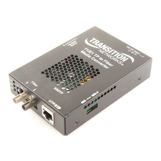
Transition Networks SSDTF10xx-10x series
Devices encode and decode T1 or E1 twisted-pair
copper signals over fiber optic cable to extend the
distance and transmission reliability of high-speed
T1 or E1 data traffic. The device is framing independent (as ESF vs. D4) and supports all
common line codes (e.g., AMI, B8ZS, HDB3).
The SSDTF10xx-10x is designed to be installed in pairs. For example, install one
SSDTF1011-105 as the "local " Device and another SSDTF1011-105 as the "remote "
Device.
Part Number
Port One - Copper
SSDTF1011-105
RJ-45
1.5 km (5,000 feet) *
SSDTF1012-105
RJ-45
1.5 km (5,000 feet) *
SSDTF1013-105
RJ-45
1.5 km (5,000 feet) *
SSDTF1014-105
RJ-45
1.5 km (5,000 feet) *
SSDTF1015-105
RJ-45
1.5 km (5,000 feet) *
SSDTF1016-105
RJ-45
1.5 km (5,000 feet) *
SSDTF1017-105
RJ-45
1.5 km (5,000 feet) *
SSDTF1018-105
RJ-45
1.5 km (5,000 feet) *
SSDTF1022-105
RJ-45
1.5 km (5,000 feet) *
SSDTF1025-105
RJ-45
1.5 km (5,000 feet) *
SSDTF1027-105
RJ-45
1.5 km (5,000 feet) *
* Typical maximum cable distance. (Actual
distance is dependent upon the physical
characteristics of the network.)
The SSDTF10xx-10x requires a CSU
between the device and the Public Telephone
Network.
Port Two - Duplex Fiber-Optic
ST, 850 nm multimode
2 km (1.2 miles)*
ST, 1310 nm single mode
8 km (4.8 miles)*
SC, 850 nm multimode
2 km (1.2 miles)*
SC, 1310 nm single mode
20 km (12.4 miles)*
SC, 1310 nm single mode
40 km (24.8 miles)*
SC, 1310 nm single mode
60 km (37.3 miles)*
SC, 1550 nm single mode
80 km (49.7 miles)*
MT-RJ, 1300 nm multimode
2 km (1.2 miles)*
ST, 1310 nm single mode
15 km (9.3 miles)*
MT-RJ, 1310 nm single mode
20 km (12.4 miles)*
ST, 1300 nm multimode
5 km (3.1 miles)*
Installation . . . . . . . . . . . . . . . . . . . . .3
Operation . . . . . . . . . . . . . . . . . . . . . .9
Cable Specifications . . . . . . . . . . . . .10
Technical Specifications . . . . . . . . . .12
Troubleshooting . . . . . . . . . . . . . . . .13
Compliance Information . . . . . . . . .16
Advertisement
Table of Contents

Summary of Contents for Transition Networks SSDTF1011-105
- Page 1 T1 or E1 data traffic. The device is framing independent (as ESF vs. D4) and supports all common line codes (e.g., AMI, B8ZS, HDB3). The SSDTF10xx-10x is designed to be installed in pairs. For example, install one SSDTF1011-105 as the “local ” Device and another SSDTF1011-105 as the “remote ” Device. Part Number...
-
Page 2: Installation
SSDTF10xx-10x Part Number Port Two - Single Fiber Optic Port One - Copper SSDTF1029-105 ** RJ-45 SC, 1310 mn (TX)/1550 nm (RX) 1.5 km (5,000 feet) * single mode, 20 km (12.4 miles)* SSDTF1029-106 ** RJ-45 SC, 1550 mn (TX)/1310 nm (RX) 1.5 km (5,000 feet) * single mode, 20 km (12.4 miles)* SSDTF1029-107 *** RJ-45... - Page 3 SSDTF10xx-10x Installation -- Continued Set the loop-back switch Hardware mode: The loop-back switch is located on the front panel of the device and is used for installation and network debugging procedures. To set the switch, use a small flat-blade screwdriver or a similar device (see the drawing to the right).
- Page 4 SSDTF10xx-10x Installation -- Continued Settings for T1 configuration (right switch set, SW 1) T1/long-haul signal Use switches 3 and 4 on the left switch set to select T1/long-haul signal (see the drawing below). Use switches 1 and 2 on the right switch set to select the proper network cable settings.
-
Page 5: Operation
Connect the power adapter plug to AC power. Verify that the device is powered by observing the illuminated LED power indicator light. For DC power, consult the user’s guide for the Transition Networks SPS1872-xx DC external power supply for powering the device. Operation After installation, the device should function without operator intervention. -
Page 6: Cable Specifications
Fiber cable Single mode fiber (recommended): 9 µm Multimode fiber (recommended): 62.5/125 µm Multimode fiber (optional): 100/140, 85/140, 50/125 µm SSDTF1011-105 850 nm multimode Fiber Optic Transmitter Power: min: -19.0 dBm Fiber Optic Receiver Sensitivity: min: -32.5 dBm Link Budget: 13.5 dB... -
Page 7: Technical Specifications
SSDTF10xx-10x Technical Specifications For use with Transition Networks Model SSDTF10xx-10x or equivalent Standards: Emissions: CISPR A; Telecordia TR-NWT-001089 (designed to meet; NOT tested); FCC Part 68; T1/E1 Physical layer: ITU-T, ANSI, AT&T, and ETSI; European Technical Standard: TBR 12; British Technical... - Page 8 Technical support Technical support is available 24 hours a day: U.S.A. and Canada: International: Transition now Chat live via the Web with Transition Networks Technical Support. Log onto www.transition.com and click the Transition Now link. Remote Device Web-based seminars Transition Networks provides seminars via live web-based training.
-
Page 9: Compliance Information
In accordance with European Union Directive 2002/96/EC of the European Parliament and of the Council of 27 January 2003, Transition Networks will accept post usage returns of this product for proper disposal. The contact information for this activity can be found in the 'Contact Us' portion of this document.


Need help?
Do you have a question about the SSDTF1011-105 and is the answer not in the manual?
Questions and answers
Provide me a link where I can, get quotation for the transition networks media converters like SSDTF10xx - 12x Stand Alone Device That can Convert E1 (input) to Fiber(output)