
Related Manuals for Flowserve PMV D3


Summary of Contents for Flowserve PMV D3
- Page 1 USER INSTRUCTIONS ® PMV D3 Digital Positioner Installation Operation FCD PMENIM0001-06 A5 - 09/16 Maintenance...
-
Page 2: Table Of Contents
Expert Calibration ....................35 8. Maintenance/service ..................37 Disassembling PMV D3 ..................37 Silencer ........................39 Potentiometer ......................40 Transmitter boards ....................40 Disassembling PMV D3 Ex ...................43 Filter change ......................44 9. Trouble shooting ....................45 10. Technical data ....................46 11. Dimensions .......................48 12. Spare parts .......................51... -
Page 3: Introduction
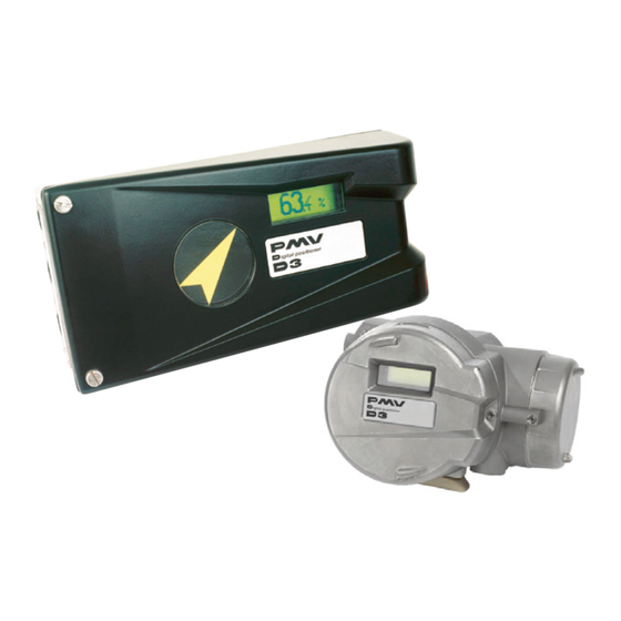
PMV D3 Digital Positioner FCD PMENIM0001-04 - 02/15 1. Introduction The Flowserve PMV D3 is a digital positioner The modules can be factory assembled before designed primarily for controlling modulating delivery or fitted later. control valves. The modules for feedback and limit switches... - Page 4 Spare parts for certified products for hazardous locations Flowserve will only supply spare parts for PMV Explosion Proof or Intrinsically Safe products to certified purchasers. In order to be allowed to purchase spare parts for IS and EX products the purchaser must be registered by a proper Notified Body and covered under PMV QAN.
-
Page 5: Storage
2. Storage General Storage in a warm place The PMV D3 positioner is a precision When the positioner is stored in a warm place instrument. It is essential that it is handled with a high relative humidity and is subjected and stored correctly. -
Page 6: Design
O-ring. Filter Pressure sensors Display, control push buttons The figure shows the PMV D3 with the cover removed. Valve block Positional feedback Integrated Gauge block (Three ports) The figure shows the PMV D3E with the covers removed. -
Page 7: Variants
5 pushbuttons and in explosion proof enclosure. The explosion local graphic LCD display. Communication proof PMV D3 features the same easy to use options include 4-20mA HART, Foundation interface for local configuration as the general Fieldbus and Profibus PA. -
Page 8: Function
PMV D3 Digital Positioner FCD PMENIM0001-06 A5 09/16 5. Function Signal converter Control signal 4 - 20 mA microprocessor Potentiometer Piezo-valve 2 Venting Piezo-valve 1 Internal pilot valve A Internal pilot valve D Diaphragm 1.2 bar (17.4 psi) Venting Pressure... -
Page 9: Installation
PMV D3 Digital Positioner FCD PMENIM0001-06 A5 09/16 6. Installation Tubing Removal of cover Use tubes with a minimum inner diameter of General purpose / Intrinsically safe Remove cover by first loosening the screw 1 Ø 6 mm (1/4”). and then the two screws 2. -
Page 10: Mounting
All versions of the PMV D3 positioner have an ISO F05 footprint, A. The holes are used to attach the PMV D3 to the mounting bracket B. Please contact PMV or your local distributor representative with actuator specifics for the proper mounting bracket and hardware. -
Page 11: Connections
PMV D3 Digital Positioner FCD PMENIM0001-06 A5 09/16 Connections Air: Port S Supply air, 2-7 bar (30–105 psi) Port C+ Connection to actuator, opening Port C- Connection to actuator, closing (only for double action) Plug for single action, see below C–... -
Page 12: Single Action Positioner, Direct Function
PMV D3 Digital Positioner FCD PMENIM0001-06 A5 09/16 Single acting positioner, Direct function Actuator with closing spring When the control signal increases, the pres- sure C+ to the actuator is increased. The C– valve stem moves upward and rotates the positioner spindle counter-clockwise. -
Page 13: Electrical Connections
5m (16.4 ft). Remote unit The remote unit shall be connected between terminals 3, 4 and 5 in the PMV D3 and 7, 8 When installing the PMV D3 Intrinsically and 9 in the remote unit. Use a shielded cable... - Page 14 For more data with electrical ratings and the relevant regulations. barrier values - please download control drawing cdwg 3-86 from www.pmv.nu/ downloads PMV D3 Ex PMV D3 Ex Profibus DP Connection Connection -P -N DGND 9 10 11 + –...
-
Page 15: Signs
PMV D3 Digital Positioner FCD PMENIM0001-06 A5 09/16 Type sign examples General purpose and Intrinsically safe housing D3IGU-D23PVA-Z5XX Ex ia IIC T4 Ga , Ta=-30..+80 C, NEMKO 03ATEX110X II 1G INTRINSICALLY SAFE/SECURITE INTRINSIQUE-Exia When installed in accordance with installation drawing:3-86C WARNING! Substitution of components may impair intrinsic safety. -
Page 16: D3 Digital Positioner Model Code
Cover and Indicator (No indicator on D3E, D3F) Black PMV, 90 deg, Arrow indicator Black, Extended travel, 270 deg Arrow indicator White cover, Flowserve, 90 deg, Arrow indicator Yellow cover, Flowserve, 90 deg, Arrow indicator Worcester Controls, Arrow indicator Sensors/Temperature/seals... -
Page 17: Control
PMV D3 Digital Positioner FCD PMENIM0001-06 A5 09/16 7. Control Menus and pushbuttons The positioner is controlled using the five BASIC MENU OUT OF SERVICE pushbuttons and the display, which are acces- MANUAL MAN/AUTO sible when the aluminum cover is removed. -
Page 18: Menu Indicator
PMV D3 Digital Positioner FCD PMENIM0001-06 A5 09/16 Menu indicator There are indicators at both sides of FULL MENU the display window and they indicate as MAN/AUTO follows: Flashing in position Out of service FULL MENU Flashing in position Manual... -
Page 19: Menu System
PMV D3 Digital Positioner FCD PMENIM0001-06 A5 09/16 Menu system BASIC MENU FULL MENU READ READ BASIC MENU FULL MENU MAN/AUTO MAN/AUTO BASIC MENU FULL MENU CALIBRATE CALIBRATE BASIC MENU FULL MENU SHIFT MENU SHIFT MENU FULL MENU STATUS FULL MENU... -
Page 20: First Start (With Calibration Sequence)
PMV D3 Digital Positioner FCD PMENIM0001-06 A5 09/16 BASIC MENU CALIBRATE First start Air leak detected/ESC = abort “Calibrate” is displayed in the basic menu OK = go on automatically, the first time power is applied. An air leak has been detected. The calibration... - Page 21 PMV D3 Digital Positioner FCD PMENIM0001-06 A5 09/16 Parameter Description BYTE Setpoint The SP has 5 bytes, 4 bytes for the float value 4+1=5 and one status byte. The status byte needs to be 128 (0x80Hex) or higher for the D3 to accept it.
- Page 22 MODE->Permitted parameter, and then choose Protocol such as MANUFAC_ID which informs MODE->Target to Man. Make sure that the unit the unique manufacturer id. For Flowserve it is is scheduled. 0x464C53. The RB has to be in AUTO for the AO-block to be Example in AUTO.
-
Page 23: Isa100 Wireless Function (Wl)
PMV D3 Digital Positioner FCD PMENIM0001-06 A5 09/16 (WL) ISA100 Wireless function The wireless D3 can be connected to an ISA100 wireless control system and perform regular control tasks. A normal update rate of the wireless AO block automatic control setpoint (OP) is 1 second. - Page 24 PMV D3 Digital Positioner FCD PMENIM0001-06 A5 09/16 BASIC MENU CALIBRATE The various menu texts are described below. Auto-tuning and calibration of end positions Auto-Cal Start tune Starts the tuning. Questions/commands are displayed during calibration. Select the type of movement, function, etc. with and confirm with OK.
- Page 25 PMV D3 Digital Positioner FCD PMENIM0001-06 A5 09/16 The menu contents are shown in the figures on the right and the texts are described below: BASIC MENU READ Current values can be read using the Read Menu and some values can be reset.
- Page 26 PMV D3 Digital Positioner FCD PMENIM0001-06 A5 09/16 BASIC MENU MAN/AUTO The Man/Auto menu is used to change between manual and automatic modes. The menu contents are shown in the figures AUT, OK=MAN OK MAN, OK=AUT on the right and the various texts are described...
- Page 27 PMV D3 Digital Positioner FCD PMENIM0001-06 A5 09/16 BASIC MENU SHIFT MENU The Shift Menu is used to choose between the basic menu and the full menu. Full menu The menu contents are shown in the figures on the right and the various texts are described...
- Page 28 PMV D3 Digital Positioner FCD PMENIM0001-06 A5 09/16 FULL MENU SETUP The Setup Menu is used for various settings. Actuator Type of actuator Size of actuator Time out Rotating actuator. Small 10 s Rotating Linear Linear actuator. Medium 25 s...
- Page 29 PMV D3 Digital Positioner FCD PMENIM0001-06 A5 09/16 Units TRVL range Select units. Setting end positions Def. Display 0%=0.0% Select value(s) to be Select Out of Service. displayed during service. Set percentage value The display reverts to for desired end position this value 10 minutes (e.g.
- Page 30 PMV D3 Digital Positioner FCD PMENIM0001-06 A5 09/16 FULL MENU TUNING Close time Minimum time (Min 0.005) from fully open to closed. Open time Minimum time (Min 0.05) from closed to fully open. Setting deadband. Min. 0.2%. Deadband Expert Advanced settings.
- Page 31 PMV D3 Digital Positioner FCD PMENIM0001-06 A5 09/16 FULL MENU ALARMS Deviation Alarm generated when deviation occurs On/Off Alarm on/off. Allowed distance before alarm is generated. Distance Time Total deviation time before alarm is generated. Alarm out Select ON/OFF offers output on terminals.
- Page 32 PMV D3 Digital Positioner FCD PMENIM0001-06 A5 09/16 Temp Alarm based on temperature Temperature alarm on/off. On/Off Temperature setting. Low temp Temperature setting. High temp Allowed hysteresis. Hysteresis Select ON/OFF offers output on terminals. Alarm out Valve act Behavior of valve when alarm is generated.
-
Page 33: Expert Calibration
Pressure LO: Use a supply of 2 bar (30 psi) (or set another value on the display). Press OK. Pot: Potentiometer setting, see section 8. Pressure read out only possible on PMV D3 Also see video on www.pmv.nu with built in pressure sensor. - Page 34 PMV D3 Digital Positioner FCD PMENIM0001-06 A5 09/16 Menu HART version READ set&pos AUT,OK=MAN MAN/AUTO & set&dev acc travel CALIBRATE & i t s t c i l l u SHIFT MENU Basic menu Menu also available for Full menu download on www.pmv.nu...
-
Page 35: Maintenance/Service
Do not take the valve block apart because its function will be impaired. When working with the PMV D3 positioner, the work place must be equipped with ESD protection before the work is started. Always turn off the air and electrical supplies before starting any work. - Page 36 PMV D3 Digital Positioner FCD PMENIM0001-06 A5 09/16 Circuit boards (PCB) Disconnect or switch off the electric power supply before starting any work. • Lift off the display PCB, D. • Release the cable connections E, F and G, • Unscrew the spacers H and lift up the...
-
Page 37: Silencer
Note: Do not disassemble the valve block • When installing the valve block — torque the four screws cross-wise to 2,5 Nm and seal with Loctite 222. ® Silencer A silencer, L (option) can be mounted under the plate M on the PMV D3. Contact PMV. -
Page 38: Potentiometer
PMV D3 Digital Positioner FCD PMENIM0001-06 A5 09/16 Potentiometer 90° and 270° spring loaded potentiometer The spring-loaded potentiometer K can be removed from the gearwheel for calibration or replacement. If the potentiometer is replaced or the setting is changed, it must be calibrated. - Page 39 PMV D3 Digital Positioner FCD PMENIM0001-06 A5 09/16 Transmitter board installation Caution! Turn off the power and air supply before starting the installation. Maintenance and repairs on PMV D3 units with hazardous area approvals should only be made by authorized staff.
- Page 40 PMV D3 Digital Positioner FCD PMENIM0001-06 A5 09/16 • Tighten the screws F, on the cam assembly. Do not tighten the screws too hard. The cams should be able to move relative to each other. • Install the inner cover with the two screws, •...
- Page 41 PMV D3 Digital Positioner FCD PMENIM0001-06 A5 09/16 Feedback option When installing the transmitter card, make sure it is placed correctly over the connector pins before gently pushing it down until it rests on the supports. Secure the PC board with the 2 screws. Make sure the holes are centred before tightening the screws.
- Page 42 PMV D3 Digital Positioner FCD PMENIM0001-06 A5 09/16 Feedback option (cont.)
-
Page 43: Disassembling Pmv D3 Ex
FCD PMENIM0001-06 A5 09/16 Disassembling PMV D3 Ex Caution! Turn off the power and air supply before disassembling the PMV D3 EX • Loosen the screws A and B and remove the caps C and D. • Remove the inner display cover E by loosening the four screws F. -
Page 44: Filter Change
PMV D3 Digital Positioner FCD PMENIM0001-06 A5 09/16 Filter change Turn off the compressed air supply before starting any work. Other wise the filter can be blown out of the positioner by the air pressure, which can be dangerous. • Remove the filter cap using a coin of suitable size. -
Page 45: Trouble Shooting
PMV D3 Digital Positioner FCD PMENIM0001-06 A5 09/16 9. Trouble shooting Symptom Action Input signal change to positioner does not • Check air supply pressure, air cleanliness, affect actuator position. and connection between positioner and actuator. • Out of service, in manual mode. -
Page 46: Technical Data
PMV D3 Digital Positioner FCD PMENIM0001-06 A5 09/16 10. Technical data Rotation angle min. 30° max 100°, option 270° Stroke 5-130 mm (0.2” to 5.1”) Input signal 4-20 mA DC Air supply 2-7 bar (30-105 psi) DIN/ISO 8573-1 3.2.3 Free from oil, water and moisture. - Page 47 PMV D3 Digital Positioner FCD PMENIM0001-06 A5 09/16 Mechanical switches Type SPDT Size Sub miniature Rating 3 A/125 VAC / 2 A/30 VDC Temp. range -30°C to 80°C (–22 °F to 180 °F) NAMUR sensors (NJ2-V3-N) Type Proximity DIN EN 60947-5-6:2000 Load current 1 mA ≤...
-
Page 48: Dimensions
PMV D3 Digital Positioner FCD PMENIM0001-06 A5 09/16 11. Dimensions 201 / 7.9” 76 / 3” 35.4 / 1.4”... - Page 49 PMV D3 Digital Positioner FCD PMENIM0001-06 A5 09/16 Dimensions with optional gauge block installed 200.6 / 7.9” 264 / 10.4” 76 / 3” 35.4 / 1.4” 240 / 9.4”...
- Page 50 PMV D3 Digital Positioner FCD PMENIM0001-06 A5 09/16 Dimensions explosion proof version 17.7 17.7 128 / 5” 100 / 3.94” 143 / 5.63” 70 / 2.8”...
-
Page 51: Spare Parts
PMV D3 Digital Positioner FCD PMENIM0001-06 A5 09/16 12. Spare parts... - Page 52 PMV D3 Digital Positioner FCD PMENIM0001-06 A5 09/16 General Purpose and Intrinsically Safe housing Part no Description D3-SP6 Black cover incl. screws D3-SP11 Internal cover incl. screws P3-SP13 Cover plate incl. screw 3-SXX Spindle adaptor (XX = 01, 02, 06, 26, 30, 36, 40, 41) 3-AS23 S23 Shaft complete incl.
- Page 53 PMV D3 Digital Positioner FCD PMENIM0001-06 A5 09/16...
- Page 54 PMV D3 Digital Positioner FCD PMENIM0001-06 A5 09/16 Explosion Proof housing Part no Description D3E-SP4 Internal cover incl. screws D3-SP1 See D3 page 53 D3-SP1-PS See D3 page 53 3E-SP8 Potentiometer complete incl. spring, holder, cable 3-AS23 S23 Shaft complete incl. gearwheel, friction clutch, spring 3-AS39 S39 Shaft complete incl.
- Page 55 PMV D3 Digital Positioner FCD PMENIM0001-06 A5 09/16 Notes...
- Page 56 (D3 Digital Positioner User Instructions) instructions The Netherlands included with the product, and train its employees and contractors in the safe use of Flowserve Flowserve Flow Control Benelux products in connection with the specific application.
Need help?
Do you have a question about the PMV D3 and is the answer not in the manual?
Questions and answers
Hi please help how to change single acting D3 positioner to double acting.
To change a Flowserve PMV D3 from a single acting positioner to a double acting positioner, the following steps must be followed:
1. Air Connections: Ensure that both air ports (C+ and C–) are connected. In single acting mode, only one port (typically C+) is used, while the other is plugged. For double acting mode, both ports must be connected to air supply.
2. Internal Configuration: The internal configuration must be modified to support double acting control. This typically involves modifying or replacing internal components such as spool valves or seals designed for single acting operation. Specific details are not provided in the context.
3. Function Setting: Verify that the positioner is set for the correct function (direct or reverse) as required by the actuator setup.
The context does not provide a complete step-by-step conversion procedure. For full details, refer to the technical section or contact the manufacturer.
This answer is automatically generated