
Related Manuals for Flowserve LMENIM5001-02


Summary of Contents for Flowserve LMENIM5001-02
- Page 1 USER INSTRUCTIONS Limitorque Master Station III Installation Operation FCD LMENIM5001-02 – 12/13 Maintenance Experience In Motion...
-
Page 2: Table Of Contents
Limitorque Master Station III FCD LMENIM5001-02 – 12/13 Contents 1. Introduction 2. Function Flowchart 3. Quick Startup 4. Connections 5. System Status 6. System Control 7. Email Configuration 8. System Configuration 9. Diagnostics 10. Troubleshooting Guide Figures Figure 1.1 - Introduction Figure 1.2 - Enter User Name... - Page 3 Limitorque Master Station III FCD LMENIM5001-02 – 12/13 Figures (Continued) Figure 8.1 - Main Menu Figure 8.2 - System Configuration Figure 8.3 - System Settings Figure 8.4 - Version Figure 8.5 - Language Menu Figure 8.6 - Clock Figure 8.7 - Time Zone Figure 8.8 - Screen Saver...
- Page 4 Limitorque Master Station III FCD LMENIM5001-02 – 12/13 Figures (Continued) Figure 10.1 - Surge Protection Access Figure 10.2 - Main AC Power Input Module Figure 10.3 - Removing Main AC Input Power Module Figure 10.4 - AC Surge Protector Figure 10.5 - Removing Fuse Holder Figure 10.6 - AC Fuse Holder...
-
Page 5: Introduction
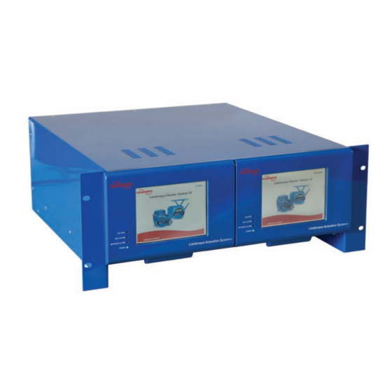
Introduction 1.1 Overview The next-generation master station is designed and manufactured by Flowserve Limitorque specifi- cally for use with the Limitorque line of (Modbus) electric actuators. The Master Station III (MSIII) acts as a single-source controller for up to 250 actuators with full redundancy, e-mail alert notifica- tion, and multi-lingual support. -
Page 6: Figure 1.1 - Introduction
Limitorque Master Station III FCD LMENIM5001-02 – 12/13 1.3 Login When the Master Station completes the boot process, it loads the Introduction screen (Figure 1.1). Figure 1.1 - Introduction Touching any part of the screen will load the Enter User Name screen (Figure 1.2). -
Page 7: Figure 1.4 - Main Menu
Limitorque Master Station III FCD LMENIM5001-02 – 12/13 Passwords and user names are set via the User Administration menu, under System Configuration. The correct password entry for the respective user name will advance the screen to the Main Menu (Figure 1.4). -
Page 8: Table 1.1 - Network Topology Cable Specifications
Limitorque Master Station III FCD LMENIM5001-02 – 12/13 1.5 Technical Data Power supply: 100-240 VAC 50/60HZ or 24 VDC. Maximum current is 1.5 A. Operating temperature: 0-60°C (32-140°F) Enclosure: Desktop/Shelf housing (standard), 19” rack mountable (optional), NEMA 4/4X wall-mountable (optional), or mounted in a stand-alone cabinet (optional). Standard dimensions are 16”... -
Page 9: Function Flowchart
Limitorque Master Station III FCD LMENIM5001-02 – 12/13 Function Flowchart The following flowchart graphics illustrate the functions of the Master Station III. flowserve.com... -
Page 10: Figure 2.1 - Function Flowchart
Limitorque Master Station III FCD LMENIM5001-02 – 12/13 Figure 2.1 - Function Flowchart... - Page 11 Limitorque Master Station III FCD LMENIM5001-02 – 12/13 Figure 2.1 - Function Flowchart (continued) flowserve.com...
-
Page 12: Quick Startup
Limitorque Master Station III FCD LMENIM5001-02 – 12/13 Quick Startup 3.1 Master Station Quick Startup Instructions 1. Connect earth ground (#14AWG minimum) wiring, MOV network cables (Belden #3074F/#9841/#3107), and power cable. 2. Apply power to the Master Station. 3. Wait for the Master Station to display the start-up screen. -
Page 13: Connections
Limitorque Master Station III FCD LMENIM5001-02 – 12/13 Connections 4.1 Master Station Rear Panel Connections Figure 4.1 - Master Station Rear Panel Connections 1. Ethernet Ports, RJ-45 connectors. One port is designated for MNET (Modbus Ethernet TCP/ IP). The other port is for the webserver. Either port may be used for either function as they are connected to the same CPU. -
Page 14: Figure 4.2 - Dcs Port Connection
Limitorque Master Station III FCD LMENIM5001-02 – 12/13 Figure 4.2 - DCS Port Connection NOTE: For cases where an existing Master Station II is being replaced with a Master Station III, an adaptor is required for communications over RS-485 or RS-422. Pin changes to support an existing MSII setup are detailed in Figure 4.3. -
Page 15: Table 4.1 - Network Channel A Connection
Limitorque Master Station III FCD LMENIM5001-02 – 12/13 6. Hot Standby unit main power switch and connector for 120 – 240 VAC. 7. Auxiliary 24 VDC power connection for Hot Standby. 8. Hot Standby DCS Port. DB-9 Female connector. Port may be RS-232 or RS-422 or RS-485. Each electrical standard uses a different wiring convention. -
Page 16: Figure 4.4 - Master Station Front Panel Connections
Limitorque Master Station III FCD LMENIM5001-02 – 12/13 4.2 Master Station Front Panel Connections Figure 4.4 - Master Station Front Panel Connections 1. Ethernet Port, RJ-45 connector. Can be used for MNET (Modbus Ethernet TCP/IP) or for the webserver. 2. Hot Standby Ethernet Port, RJ-45 connector. Can be used for MNET (Modbus Ethernet TCP/IP) or for the webserver. - Page 17 Limitorque Master Station III FCD LMENIM5001-02 – 12/13 4.3 Master Station Wiring Requirements The network cable connects the field units to the host controller or Master Station. Belden 3074F, 3105A, or 9841 shielded, twisted-pair cable should be used. The use of other cables may result in a reduction of internodal distances or increased error rate, and is the user’s responsibility.
-
Page 18: Figure 4.6 - Modbus Redundant Loop Topology
Limitorque Master Station III FCD LMENIM5001-02 – 12/13 4.4 Master Station Network Topologies Figure 4.6 - Modbus Redundant Loop Topology MASTER STATION III Legend Channel A Channel B - Motor-operated valve - Data A1 Diagnostic Note: - Data A1* Polarity and level of the network’s data connection... -
Page 19: System Status
Limitorque Master Station III FCD LMENIM5001-02 – 12/13 System Status 5.1 Main Menu Upon successful login as a user assigned to any role level, the System Status button on the Main Menu screen will be present. Simply touching the System Status button will advance the HMI display to the System Status screen (Figure 5.2). -
Page 20: Figure 5.2 - System Status
Limitorque Master Station III FCD LMENIM5001-02 – 12/13 5.2 System Status The System Status main screen (Figure 5.2) allows the user to view the overall status of the MOV network and Master Station. Figure 5.2 - System Status 5.2.1 Network Status The Network Status screen presents an overview of the entire field unit network, up to 25 activated MOVs per page. -
Page 21: Figure 5.4 - Mov Status
Limitorque Master Station III FCD LMENIM5001-02 – 12/13 5.2.2 MOV Status The MOV Status screen reveals the actual MOV network address, tag name, unit type, and position. In addition, it shows the status of the MOV communication channels and the Modbus holding registers that have been selected to be mapped to the PLC/DCS data table. -
Page 22: System Control
Limitorque Master Station III FCD LMENIM5001-02 – 12/13 System Control 6.1 Main Menu Upon successful login as a user assigned to a Control, Configure, or Administrator role, the System Control button on the Main Menu (Figure 6.1) will be present. Simply touching the System Control button will advance the HMI display to the System Control screen (Figure 6.2). -
Page 23: Figure 6.2 - System Control
Limitorque Master Station III FCD LMENIM5001-02 – 12/13 Figure 6.2 - System Control 6.2.1 MOV Control The MOV Control screen (Figure 6.3) allows for a selected MOV to be opened, stopped, closed, or moved to a set position (such as 38% open). As shown in Figure 6.3, if the torque register is selected (see Section 8.2.5.3.2), the MOV Control screen displays the torque reading during MOV operation... -
Page 24: Figure 6.5 - Emergency Shutdown
Limitorque Master Station III FCD LMENIM5001-02 – 12/13 6.2.2 Emergency Shutdown Should it be necessary to initiate an Emergency Shutdown of the networked MOVs, this can be accomplished by accessing the Emergency Shutdown screen (Figure 6.5) from the Main Menu. -
Page 25: Figure 6.7 - Emergency Shutdown Termination
Limitorque Master Station III FCD LMENIM5001-02 – 12/13 When an emergency shutdown is terminated, the Emergency Shutdown Termination in Progress screen will be displayed (Figure 6.7) until the procedure is complete. Figure 6.7 - Emergency Shutdown Termination When an emergency shutdown is either initiated or terminated, the Emergency Shutdown action screen will display a listing of the networked MOVs and their acknowledgement of the signal. -
Page 26: Email Configuration
Limitorque Master Station III FCD LMENIM5001-02 – 12/13 Email Configuration 7.1 Main Menu Upon successful login as a user assigned to either Configure or Administrator role level, the System Configuration button on the Main Menu screen will be present. Simply touching the Email Configuration button will advance the HMI display to the Email Notification Screen (Figure 7.2). -
Page 27: Figure 7.2 - Email Notification Screen
Limitorque Master Station III FCD LMENIM5001-02 – 12/13 Figure 7.2 - Email Notification Screen 7.2.1 SMTP Configuration NOTE: SMTP Email Setup must be completed before email addresses can be added to the mailing list. Email notification is enabled by setting up a SMTP server and valid email account in the Master Station III. -
Page 28: Figure 7.5 - Smtp Configuration With Password
Limitorque Master Station III FCD LMENIM5001-02 – 12/13 Figure 7.5 - SMTP Configuration with Password Once the SMTP Host Address and SMTP Email Account have been configured, the IP address of the Master Station III must be set in the Email Notification Screen. Set the Primary and Secondary DNS addresses by selecting the octet fields. -
Page 29: Figure 7.7 - Alarm Selections
Limitorque Master Station III FCD LMENIM5001-02 – 12/13 After entering desired email address, the Master Station will send a confirmation email to the address. Check the email account to verify that the email address was entered correctly. Following the email verification, the Master Station returns to the Email Notification screen where the email address can be selected and alerts added to the selected email. -
Page 30: System Configuration
Limitorque Master Station III FCD LMENIM5001-02 – 12/13 System Configuration 8.1 Main Menu Upon successful login as a user assigned to either Configure or Administrator role level, the System Configuration button on the Main Menu screen will be present. Simply touching the System Configuration button will advance the HMI display to the System Configuration screen (Figure 8.2). -
Page 31: Figure 8.2 - System Configuration
Limitorque Master Station III FCD LMENIM5001-02 – 12/13 8.2 System Configuration The System Configuration main menu allows the user to view/configure eight distinct areas within the Master Station: System Information: provides current firmware version and access to settings for language, clock and screensaver. -
Page 32: Figure 8.3 - System Settings
Limitorque Master Station III FCD LMENIM5001-02 – 12/13 Figure 8.3 - System Settings 8.2.1.1 Version The Version screen (Figure 8.4) displays the Master Station’s currently loaded firmware version. Figure 8.4 - Version 8.2.1.2 Language The Language menu (Figure 8.5) allows the user to set the unit’s display language by selecting the desired language button. -
Page 33: Figure 8.6 - Clock
Limitorque Master Station III FCD LMENIM5001-02 – 12/13 Figure 8.6 - Clock Additionally, the Master Station Clock can be set to the correct local time zone by selecting the Time Zone button in the Clock screen. The time zone is configured by selecting the region and locale in which the Master Station is located. -
Page 34: Figure 8.9 - Configure Hot Standby
Limitorque Master Station III FCD LMENIM5001-02 – 12/13 8.2.2 Redundant Configuration The Configure Hot Standby screen (Figure 8.9) enables the user to configure the Master Station for Hot Standby operation. The requested mode and startup mode can be set to Active, Standby, or Disabled. -
Page 35: Figure 8.11 - Tag List
Limitorque Master Station III FCD LMENIM5001-02 – 12/13 Figure 8.11 - Tag List 8.2.4 User Administration The User Administration screen (Figure 8.12) is accessible when the user is logged in as an Administrator (see User Rights Overview in Section 1). It permits the addition or deletion of individual users, as well as the assignment of user passwords and roles within the Master Station. -
Page 36: Figure 8.13 - Enter New Username
Limitorque Master Station III FCD LMENIM5001-02 – 12/13 Figure 8.13 - Enter New Username Figure 8.14 - Enter New Password 8.2.4.2 Delete User To remove a user account from accessing the Master Station, tap the “Delete User” button on the User Administration screen. -
Page 37: Figure 8.16 - User Settings
Limitorque Master Station III FCD LMENIM5001-02 – 12/13 8.2.4.3 User Settings To modify user privileges on the Master Station, tap the “User Settings” button on the User Administration screen. A listing of all the user accounts on the Master Station are displayed as demonstrated in Figure 8.16. -
Page 38: Figure 8.17 - Change Password
Limitorque Master Station III FCD LMENIM5001-02 – 12/13 Figure 8.17 - Change Password Figure 8.18 - Enter New Password... -
Page 39: Figure 8.19 - Dcs Configuration
Limitorque Master Station III FCD LMENIM5001-02 – 12/13 8.2.5 DCS Configuration The DCS Configuration screen (Figure 8.19) allows the user to configure communication port parameters in order to successfully link the Master Station to the control system’s Host device (DCS/ PLC/etc.). -
Page 40: Figure 8.21 - Configure Ethernet Port
Limitorque Master Station III FCD LMENIM5001-02 – 12/13 DCS Address: DCS address of the Master Station III unit. Timeout: Defines the maximum acceptable response delay time from the MSIII after request sent by Master. Parity: Error checking option for serial communication. -
Page 41: Figure 8.23 - Fc-02 Read Input Status
Limitorque Master Station III FCD LMENIM5001-02 – 12/13 8.2.5.3.1 Modbus FC 02 Read Input Status Touching the “Modbus FC 02 Read Input Status” button will take the user to the FC 02 Read Input Status Screen (Figure 8.23) for selection of desired input status bits from field unit holding registers 9-13. - Page 42 Limitorque Master Station III FCD LMENIM5001-02 – 12/13 Table 8.1 - Status Bit Definitions (continued) Modbus Bit Number MX/DDC Address Open inhibit active Close inhibit active Not used Not used One or more phases is missing Reverse phase sequence is occurring...
- Page 43 Limitorque Master Station III FCD LMENIM5001-02 – 12/13 Table 8.1 - Status Bit Definitions (continued) Modbus Bit Number MX/DDC Address Not used Not used User Input 0 User Input 1 User Input 2 Remote stop input Remote open input Remote close input...
-
Page 44: Figure 8.24 - Modbus Holding Registers
Limitorque Master Station III FCD LMENIM5001-02 – 12/13 Table 8.2 - Function Code -02 Example Message Breakdown Query Response MSIII Unit Address MSIII Unit Address Function Function Starting Address Hi Byte Count Starting Address Lo Data (Inputs 10088 - 10081; MOV2) No. -
Page 45: Figure 8.25 - Fc-03 Sample Data Table
Limitorque Master Station III FCD LMENIM5001-02 – 12/13 Figure 8.25 - FC-03 Sample Data Table NOTE: Data table shown with only registers 8 and 9 (Position and Status) selected. This function code is used to read the binary contents of holding registers. This function code is typically used during the network polling cycle. -
Page 46: Table 8.4 - Register Definitions
Limitorque Master Station III FCD LMENIM5001-02 – 12/13 Table 8.4 - Register Definitions Register # Description Meaning Command Registers 1 and 2 are write-only registers used for Modbus Function Code 06 Argument Registers 1 and 2 are write-only registers used for Modbus... - Page 47 Limitorque Master Station III FCD LMENIM5001-02 – 12/13 Table 8.4 - Register Definitions (continued) Register # Description Meaning Fault Register 16 Bits of field status Bit 0 Open inhibit active Bit 1 Close inhibit active Bit 2 Not Used Bit 3 Not Used...
-
Page 48: Table 8.4 - Register Definitions
Limitorque Master Station III FCD LMENIM5001-02 – 12/13 Table 8.4 - Register Definitions (continued) Register # Description Meaning Digital Inputs 2 Value of 16 Digital Inputs Bit 0 Analog board 1 present Bit 1 Analog board 2 present Bit 2 Analog Input 1 lost... -
Page 49: Figure 8.26 - Modbus Coils
Limitorque Master Station III FCD LMENIM5001-02 – 12/13 8.2.5.3.3 Modbus FC 05/15 Force Coils Touching the “Modbus FC 05/15 Force Coils” button will take the user to the Modbus Coils screen (Figure 8.26) for selection of desired field unit coils. Note that the Close and Open Contactor coils are always included in the data table. -
Page 50: Table 8.5 - Ddc-100 Coil Assignments, Modbus 05 Command Usage For Digital Outputs
Limitorque Master Station III FCD LMENIM5001-02 – 12/13 Function code -05 is used to force a single coil. Forcing the individual coil either ON (1) or OFF (0) will energize or de-energize a coil (digital output). Coil 1 in the field unit closes the actuator and Coil 2 opens the actuator. -
Page 51: Figure 8.28 - Modbus Holding Registers-One Per Mov
Limitorque Master Station III FCD LMENIM5001-02 – 12/13 Example of force multiple coils command Force coil 2 of field unit 23 ON. This will CLOSE the valve controlled by field unit 23. Additionally, force coil 1 of field unit 24 ON. This will OPEN the valve controlled by field unit 24. -
Page 52: Figure 8.30 - Fc-06/16 Sample Data Table With 'One Per Mov' Selected
Limitorque Master Station III FCD LMENIM5001-02 – 12/13 Selecting the “Next” button will advance the screen to a sample data table screen as shown below. Please note that a unique data table is created starting at register 45001. Specific field unit registry convention is as follows: DCS Command Write Register = [(MOV address –1) * (selected number... -
Page 53: Table 8.9 - Function Code -06 Second Command Message Breakdown
Limitorque Master Station III FCD LMENIM5001-02 – 12/13 Register Address Lo Register Address Lo (Register 45201; MOV101) Force Data Hi Force Data Hi Force Data Lo Force Data Lo 8F7B Error Check (CRC) 8F7B Error Check (CRC) NOTE 1: 1450h equals register address 45201 (field unit 101 command register) -
Page 54: Table 8.11 - Function Code -16 Message Breakdown
Limitorque Master Station III FCD LMENIM5001-02 – 12/13 Table 8.11 - Function Code -16 Message Breakdown Query Response MSIII Unit Address MSIII Unit Address Function Function Starting Address Hi Starting Address Hi (Register 45050; MOV50) Starting Address Lo Starting Address Lo (Register 45050; MOV50) - Page 55 Limitorque Master Station III FCD LMENIM5001-02 – 12/13 Other registers may also be preset to control or change other functions but care must always be taken to properly change these values. An improper value written to a register can cause undesirable actions from the DDC-100 Field Unit.
-
Page 56: Figure 8.32 - Mov Network Configuration
Limitorque Master Station III FCD LMENIM5001-02 – 12/13 8.2.6 MOV Network Config The MOV Network Config screen (Figure 8.32) provides access to communication parameters essential for connecting the Master Station to all assigned field units. By selecting the Next button, the screen will advance to Active MOVs display (Figure 8.33) which allows the user to add additional... -
Page 57: Figure 8.34 - Polling Priority-Active Movs
Limitorque Master Station III FCD LMENIM5001-02 – 12/13 Figure 8.34 - Polling Priority-Active MOVs In order to optimize the network efficiency, lower priority MOVs can be set to be polled at a user defined cycle. 8.2.7 File Manager The File Manager screen (Figure 8.35) allows the user to import/load/export the Master Station configuration file, export the event log, and import the MOV tag name files. -
Page 58: Figure 8.35 - File Manager
Limitorque Master Station III FCD LMENIM5001-02 – 12/13 NOTE: File Manager is disabled when the unit is running in “Active” mode. To turn off “Active” mode and access the File Manager, go to the System Configuration menu as detailed in Section 8.1 and select the “Redundant Config”... -
Page 59: Figure 8.37 - Import Tag File
Limitorque Master Station III FCD LMENIM5001-02 – 12/13 8.2.8.2 Import Tag File The Import Tag File screen (Figure 8.37) allows the user to access the file chooser and select an MOV tag name file from a connected USB Flash Drive to be loaded into the Master Station’s MOV tag configuration settings. -
Page 60: Figure 8.39 - Export Config File
Limitorque Master Station III FCD LMENIM5001-02 – 12/13 8.2.8.4 Export Config File The Export Configuration screen (Figure 8.39) enables the user to access the file chooser and save a selected configuration file to a connected USB Flash Drive. Figure 8.39 - Export Config File 8.2.8.5 Export Event Log... -
Page 61: Figure 8.41 - Update Software
Limitorque Master Station III FCD LMENIM5001-02 – 12/13 8.2.8.6 Update Software The Import Software Update screen (Figure 8.41) allows the user to access the file chooser and select a software update file to be copied to the default directory for the Master Station device software file archives. -
Page 62: Diagnostics
Limitorque Master Station III FCD LMENIM5001-02 – 12/13 Diagnostics 9.1 Main Menu Upon successful login as a user assigned to either Configure or Administrator role level, the Diagnostics button on the Main Menu screen will be present (Figure 9.1). Simply touching the Diagnostics button will advance the HMI display to the Diagnostics screen (Figure 9.2). -
Page 63: Figure 9.2 - Diagnostics
Limitorque Master Station III FCD LMENIM5001-02 – 12/13 Figure 9.2 - Diagnostics 9.2.1 Event Log The Event Log screen (Figure 9.3) allows the user to display the last 20 events that occurred. Each event is related to changes in login Information, configuration, network status, or MOV polling activity. -
Page 64: Figure 9.4 - Comm/Fc Logger
Limitorque Master Station III FCD LMENIM5001-02 – 12/13 9.2.2 Comm/FC Logger The Comm/FC Logger (Figure 9.4) captures Modbus requests and responses to/from the DCS and MOVs (channel A & B). Additionally, the Logger screen shows configuration changes related to channel A and/or B, Ethernet, and DCS port activity, as well as individual function codes. The channels can be selected individually to filter activity being displayed. -
Page 65: Troubleshooting Guide
Limitorque Master Station III FCD LMENIM5001-02 – 12/13 Troubleshooting Guide 10.1 Front Panel Indicators There are four LEDs on the front of the Master Station that provide a visual reference of the overall health of the Master Station and MOV network. These LEDs are described as follows: A. - Page 66 Limitorque Master Station III FCD LMENIM5001-02 – 12/13 10.4 Error Messages Problem Saving File – Media Error (Full, Write Protected, Corrupted) No USB Device Selected - Configuration save attempted without a USB device inserted in a USB port, and selected.
-
Page 67: Figure 10.1 - Surge Protection Access
Limitorque Master Station III FCD LMENIM5001-02 – 12/13 10.6 Surge Protection Figure 10.1 - Surge Protection Access AC Fuse Protection AC Surge Protection Network Surge Protection (behind panel) (behind panel) 10.6.1 AC Surge Protection It is recommended to replace the surge protector if a known primary AC power surge has occurred. -
Page 68: Figure 10.3 - Removing Main Ac Input Power Module
Limitorque Master Station III FCD LMENIM5001-02 – 12/13 Figure 10.3 - Removing Main AC Input Power Module Locate the AC surge protector, unplug wiring connector on both sides of the protector, and remove it from the cable assembly. Figure 10.4 - AC Surge Protector Install replacement protector by following above procedures in reverse order. -
Page 69: Figure 10.6 - Ac Fuse Holder
Limitorque Master Station III FCD LMENIM5001-02 – 12/13 Figure 10.6 - AC Fuse Holder Check each of the two fuses, located in the holder, for continuity. Replace if necessary and reinstall the holder into the module. 10.6.3 Network Surge Protection The network surge protector is a three-stage device for protection of the RS-485 data lines. - Page 70 Flowserve Corporation has established industry leadership in the design and manufacture of its products. When properly selected, this Flowserve product is designed to perform its intended function safely during its useful life. However, the purchaser or user of Flowserve products should be aware that Flowserve products might be used in numerous applications under a Facsimile: 86-10-6561-2702 wide variety of industrial service conditions.
Need help?
Do you have a question about the LMENIM5001-02 and is the answer not in the manual?
Questions and answers