Table of Contents
Advertisement
WS-12 Wireless 8 Channel Professional Weather Station
with Temperature Spectrum Color Changing Backlight
Table of Contents
1
Introduction ............................................................................................................................... 2
2
Warnings ................................................................................................................................... 2
3
Quick Start Guide ...................................................................................................................... 3
4
Getting Started .......................................................................................................................... 3
4.1
Parts List ........................................................................................................................... 3
4.2
Recommend Tools ............................................................................................................ 5
4.3
Anemometer Assembly Sensor Set Up ............................................................................. 5
4.4
Rain Gauge Assembly Set Up .......................................................................................... 6
4.5
Thermo-Hygrometer Sensor Set Up ................................................................................. 8
4.6
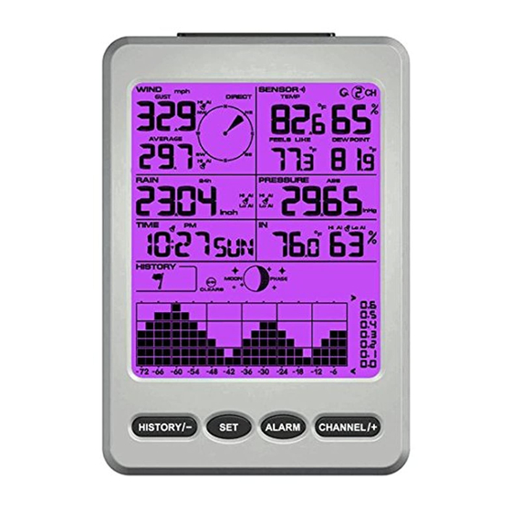
Display Console ............................................................................................................. 10
4.6.1 Display Console Layout .............................................................................................. 10
4.6.2
Display Console Set Up ............................................................................................. 12
4.6.3
Sensor Operation Verification .................................................................................... 13
5
Weather Station Installation .................................................................................................... 14
5.1
Pre-Installation Checkout ............................................................................................... 14
5.2
Site Survey ..................................................................................................................... 14
5.3
Best Practices for Wireless Communication .................................................................. 15
6
Final Sensor Installation .......................................................................................................... 15
6.1
Anemometer Installation ................................................................................................ 15
6.2
Rain Gauge Installation .................................................................................................. 18
6.3
Thermo-Hygrometer Installation .................................................................................... 19
7
Console Operation................................................................................................................... 20
7.1
Quick Display Mode ...................................................................................................... 20
7.2
Set (Program) Mode ....................................................................................................... 21
7.3
Restore Factory Default.................................................................................................. 23
7.4
Channel Selection ........................................................................................................... 24
7.5
Sensor Search Mode ....................................................................................................... 24
7.6
History Graph Mode ....................................................................................................... 24
7.7
Reset Min/Max record .................................................................................................... 25
7.8
Snooze Mode .................................................................................................................. 25
7.9
Backlight Mode .............................................................................................................. 25
Version 1.1
User Manual
1
Page
Advertisement
Table of Contents

Related Manuals for Ambient Weather WS-12


Summary of Contents for Ambient Weather WS-12
-
Page 1: Table Of Contents
WS-12 Wireless 8 Channel Professional Weather Station with Temperature Spectrum Color Changing Backlight User Manual Table of Contents Introduction ..........................2 Warnings ........................... 2 Quick Start Guide ........................3 Getting Started .......................... 3 Parts List ........................... 3 Recommend Tools ......................5 Anemometer Assembly Sensor Set Up ................ -
Page 2: Introduction
17 Warranty Information ......................... 39 1 Introduction Thank you for your purchase of the WS-12 Wireless 8 Channel Professional Weather Station with Temperature Spectrum Color Changing Backlight. The following user guide provides step by step instructions for installation, operation and troubleshooting. To download the latest manual and additional troubleshooting tips, please visit: http://ambientweather.wikispaces.com/ws12... -
Page 3: Quick Start Guide
Clear any total rain that may have accumulated during the set up. 4 Getting Started The WS-12 weather station consists of a display console (receiver), a sensor array with thermo-hygrometer, rain gauge, wind sensor, and mounting hardware. 4.1 Parts List... - Page 4 Item Image Rain Gauge Filter Dimensions: 2.48 x 2.48 x 1.1in Anemometer (WS-12-WV) Dimensions: 3 ¼ x 6 x 8 ½” Anemometer Mounting Bracket (with pole insert) Dimensions: 3 x 4 x 1 ½” Anemometer Mounting Bracket Back Plate (pole mount) Dimensions: 3 x 3 x 1 ”...
-
Page 5: Recommend Tools
Item Image Manual Power Adapter Figure 1 4.2 Recommend Tools Phillips Precision screwdriver Size: PH0 and PH2 Compass or GPS (for wind direction calibration) Adjustable Wrench Hammer and nail for hanging remote thermo-hygrometer transmitter. 4.3 Anemometer Assembly Sensor Set Up The anemometer assembly consists of the wind cups, wind vane, solar panel, bubble level, sensor mounting bracket and mounting foot. -
Page 6: Rain Gauge Assembly Set Up
Locate the battery door on the anemometer transmitter, push and open the battery compartment, as shown in Figure 3. Figure 3 Insert four batteries into the battery compartment, then press the reset button, as shown in Figure Note: Use high quality alkaline batteries, which have an operational temperature range of -4 to 140 °F. - Page 7 Figure 5 Rotate and detach the rain gauge funnel, as shown in Figure 6. Figure 6 Locate the battery door on the rain gauge transmitter, pull out the battery compartment, as shown in Figure 7. Version 1.1 ©Copyright 2016, Ambient LLC. All Rights Reserved. Page...
-
Page 8: Thermo-Hygrometer Sensor Set Up
Figure 7 4.5 Thermo-Hygrometer Sensor Set Up Remove the battery door on the back of the sensor by removing the set screw, as shown in Figure Figure 8 1. BEFORE inserting the batteries, locate the dip switches on the inside cover of the lid of the transmitter. - Page 9 Figure 9 Channel Number: The WS-11 supports up to eight transmitters. To set each channel number (the default is Channel 1), change Dip Switches 1, 2 and 3, as referenced in Table 1. Temperature Units of Measure: To change the transmitter display units of measure (°F vs.
-
Page 10: Display Console
Figure 10 temperature °F vs. °C) (2) temperature units ( (3) channel number (4) relative humidity 5. Close the battery door. Make sure the gasket (around the battery compartment) is properly seated in its trace prior to closing the door. Tighten the set screw. 4.6 Display Console 4.6.1 Display Console Layout The display console layout is shown in Figure 11. - Page 11 Figure 11 1. Indoor temperature and humidity display 15. Wind direction 2. Indoor temperature and humidity HI/LO 16. Wind gust HI alarm icon alarm icon 17. Wind speed units of measure 3. Pressure (REL and ABS) display 18. Wind gust display 4.
-
Page 12: Display Console Set Up
4.6.2 Display Console Set Up Note: Power up the rain gauge, anemometer and thermos-hygrometer sensors first before powering up the console. If you power up the console first, you will need to resynchronize the sensors. Make certain the weather station sensors are at least 10’away from the console and within 100’of the console. -
Page 13: Sensor Operation Verification
While in the search mode, the remote search icon will be constantly displayed. If you have more than one thermo-hygrometer sensor (up to eight thermo-hygrometer sensors are supported), the display will automatically toggle between sensors until all sensors have reported in. If it does not update, please reference the troubleshooting guide in Section 13. -
Page 14: Weather Station Installation
Make sure your display console is at least five feet away from any electronic device to avoid interference. 6. Visit Ambient Weather Mounting Solutions for assistance and ideas for mounting your Version 1.1 ©Copyright 2016, Ambient LLC. All Rights Reserved. -
Page 15: Best Practices For Wireless Communication
weather station: http://www.ambientweather.com/amwemoso.html 5.3 Best Practices for Wireless Communication Wireless communication is susceptible to interference, distance, walls and metal barriers. We recommend the following best practices for trouble free wireless communication. 1. Electro-Magnetic Interference (EMI). Keep the console several feet away from computer monitors and TVs. - Page 16 Figure 13 Fasten the wind transmitter to mounting pole brackets with foot-mounting, two ∅3 bolts and M3 nuts, as shown in Figure 14. Figure 14 Tighten the included mounting pole to your mounting pole (purchased separately) with the four ∅5 Bolts and M5 Nuts assembly, or fix on the wall with four tapping screws, as shown in Figure 15.
- Page 17 Figure 15 Version 1.1 ©Copyright 2016, Ambient LLC. All Rights Reserved. Page...
-
Page 18: Rain Gauge Installation
6.2 Rain Gauge Installation Figure 16 Remove the rain gauge funnel from the base prior to installation by rotating the counter clockwise until the tabs on the base and the funnel align, then pulling upwards. Fasten the rain gauge to the mounting pole, as shown in Figure 17. Figure 17 Version 1.1 ©Copyright 2016, Ambient LLC. -
Page 19: Thermo-Hygrometer Installation
Tighten the rain gauge to your mounting pole or bracket with two U-bolts and four M5 nuts , or fix on a horizontal surface with the four tapping screws, as shown in Figure 18. Reattach the funnel by aligning the tabs on the funnel and base, and rotate clockwise. Figure 18 6.3 Thermo-Hygrometer Installation It is recommended you mount the remote sensor outside in a shaded area. -
Page 20: Console Operation
7 Console Operation Note: The console has five operational keys: HISTORY/- key, SET key, ALARM key, CHANNEL/+ and SNOOZE/LIGHT key. 7.1 Quick Display Mode Note: To exit the Quick Display Mode at any time, press the SNOOZE/LIGHT button on the top of the display console. -
Page 21: Set (Program) Mode
Note: The graph displays hours on the horizontal or x-axis (the most recent data to the right of the graph). For example, 0h is the current data and -12 is 12 hours ago. The vertical axis or y-axis auto-scales, displays the deviation from the current value (the most recent data will always display 0). - Page 22 12. Barometric Pressure Display Units (default: inHg). Press the SET key again to change the pressure units of measure. Press the [+] key or [-] key to toggle the pressure units between mmhg, inHg or hPa. 13. Backlight Color Setting (default: Outdoors). Press the SET key again to set the backlight color defined parameter (the LED icon will be displayed).
-
Page 23: Restore Factory Default
>100 >85 Note: This manual is not printed in color. To view the actual color chart, visit: http://site.ambientweatherstore.com/Manuals/WS-12.pdf to view the actual color. Note: Reference Section 9.3 to modify the color changes to best suit your comfort level and location. -
Page 24: Channel Selection
7.4 Channel Selection Press the CHANNEL/+ button to switch the display between remote sensors 1 through 8, and scroll mode . In scroll mode, all of the indoor and detected outdoor sensors will be displayed in five second intervals. 7.5 Sensor Search Mode If a sensor loses communication, dashes (--.-) will be displayed. -
Page 25: Reset Min/Max Record
current channel displayed. 7.7 Reset Min/Max record Note: If you own more than one thermo-hygrometer sensor, the minimum and maximum value of all channels will be cleared in the reset mode. In normal mode, press (do not hold) the ALARM key, and the MAX icon will be displayed. Press the HISTORY/- key to view rainfall (1h, 24h, week or month) and pressure (ABS or REL) max value. -
Page 26: Adjustment Or Calibration
The purpose of your weather station is to measure conditions of your surroundings, which vary significantly from location to location. The WS-12 supports up to eight remote sensors. Each of the eight sensors can be calibrated. If you own more than one remote sensor, press the CHANNEL/+ button first to display the specific channel you wish to calibrate. -
Page 27: Humidity Calibration
Press the [+] or [-] key to increase or decrease the temperature reading (in increments of 0.1). Press and hold the [+] or [-] key for three seconds to increase or decrease rapidly. Press the ALARM key to reset current value. Press the SET key switch to next channel (1through 8). - Page 28 speed calibration factor from 0.75 to 1.25, where: Calibrated Wind Speed = Calibration factor x Measured Wind Speed Note: The wind gust is also affected by the wind speed calibration factor. Discussion: Wind speed and wind gust are adversely affected by installation constraints. The rule of thumb is to install the weather station four times the distance of the height of the tallest obstruction (for example, a 6 m house would require an installation 24 m away).
-
Page 29: Alarm Mode
To determine the relative pressure for your location, locate an official reporting station near you (the internet is the best source for real time barometer conditions, such as Weather.com or Wunderground.com), and set your weather station to match the official reporting station. 8 Alarm Mode The WS-12 includes the following alarms: Time ... -
Page 30: Setting The Alarms
Press the ALARM key to view the LOW alarms along with the alarm clock time. Press the SET key to view rainfall (1h and 24h) high alarm and pressure (ABS and REL) high/low alarm. Press the SNOOZE/LIGHT key at any time to return to the normal mode 8.3 Setting the Alarms Press and hold the ALARM key for three seconds to enter the alarm mode. -
Page 31: Alarm And Command Key Beeper On/Off Mode
18. Relative pressure low alarm 19. Indoor temperature high alarm 20. Indoor temperature low alarm 21. Indoor humidity high alarm 22. Indoor humidity low alarm Note: To prevent repetitive temperature alarming, there is a 0.9 °F tolerance band. For example, if you set the high alarm to 80.0 °F and silence the alarm, the alarm icon will continue to flash until the temperature falls below 79.1°F, at which point, the alarm will reset and must increase above 80.0 °F to activate again. - Page 32 Figure 21 At temperatures greater than 80°F, the heat index is displayed, as shown in the National Weather Service Heat Index Table below: Figure 22 When the temperature is between 40°F and 80°F, the Channel 1 temperature is displayed (Feels Like temperature is the same as Channel 1 temperature).
-
Page 33: Moon Phase
9.2 Moon Phase The following moon phases are displayed based on the calendar date. Figure 23 9.3 Personalizing Color Ranges You can customize your background color ranges to suit your location, or personal preferences. For example, if you live in Alaska, your definition of hot and cold may be very different if you live in Arizona. -
Page 34: Glossary Of Terms
10 Glossary of Terms Term Definition Accuracy Accuracy is defined as the ability of a measurement to match the actual value of the quantity being measured. Hygrometer A hygrometer is a device that measures relative humidity. Relative humidity is a term used to describe the amount or percentage of water vapor that exists in air. -
Page 35: Measurement Specifications
11.2 Measurement Specifications The following table provides specifications for the measured parameters. The following table provides specifications for the measured parameters. Measurement Range Accuracy Resolution Indoor Temperature 32 to 140 °F ± 1 °F 0.1 °F Outdoor Temperature -40 to 140 °F ±... - Page 36 Problem Solution console. displayed. Once the signal is reacquired, the remote search icon will turn off, and the current values will be displayed. The maximum line of sight communication range is 300 feet and 100 feet under most conditions. Move the sensor assembly closer to the display console.
-
Page 37: Maintenance
Solar Radiation Shield improves temperature accuracy for hot weather SRS100LX Temperature climates. Install over thermo-hygrometer. and Humidity Solar Radiation Shield Ambient Weather Humidity One step calibration kits for digital hygrometers use salt slurry formula Calibration Kits to accurately calibrate the indoor and outdoor hygrometers. 15 Liability Disclaimer Please help in the preservation of the environment and return used batteries to an authorized depot. -
Page 38: Fcc Statement
wild country and/or in unauthorized grounds strongly damages the environment. Reading the “User manual” is highly recommended. The manufacturer and supplier cannot accept any responsibility for any incorrect readings and any consequences that occur should an inaccurate reading take place. This product is designed for use in the home only as indication of weather conditions. -
Page 39: Warranty Information
• Connect the equipment into an outlet on a circuit different from that to which the receiver is connected. • Consult the dealer or an experienced radio/TV technician for help. 17 Warranty Information Ambient, LLC provides a 1-year limited warranty on this product against manufacturing defects in materials and workmanship.
Need help?
Do you have a question about the WS-12 and is the answer not in the manual?
Questions and answers