Table of Contents
Advertisement
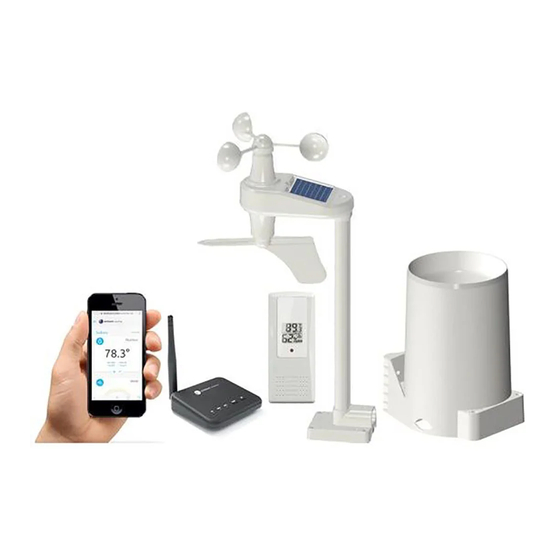
Ambient Weather WS-100 Wi-Fi Smart Weather Station User
Table of Contents
Contents
................................................................................................................................................ 3
1.
.................................................................................................................................................... 4
2.
3.
4.
........................................................................................................................................................... 4
4.4
5.
6.
............................................................................................................................................. 9
...................................................................................................................................... 12
6.2
6.3
6.4
6.5
Version 1.0
....................................................................................................................................... 4
........................................................................................................................... 4
............................................................................................................................. 5
............................................................................................................................... 6
................................................................................................................... 8
....................................................................................................... 8
...................................................................................................................................... 8
................................................................................................................ 9
...................................................................................................................... 9
................................................................................................................... 10
...................................................................................................................... 12
.................................................................................................................... 13
........................................................................................................ 14
......................................................................................................... 14
....................................................................................................... 16
............................................................................................................................. 22
........................................................................................................ 23
........................................................................................................ 23
...................................................................................................... 25
.......................................................................................................... 26
................................................................................................................................. 27
©Copyright 2020, Ambient LLC. All Rights Reserved.
Manual
................................................................................ 7
................................................................................ 8
........................................................................ 17
....................................................................... 17
Page 1
Advertisement
Table of Contents

Related Manuals for Ambient Weather WS-100


Summary of Contents for Ambient Weather WS-100
-
Page 1: Table Of Contents
Ambient Weather WS-100 Wi-Fi Smart Weather Station User Manual Table of Contents Contents ..............................3 Introduction ..............................4 Warnings ............................4 Quick Start Guide Parts ................................4 ........................... 4 4.1 Wi-Fi Module (included) ..........................5 4.2 Anemometer (optional) 4.3 Rain Gauge (optional) .......................... - Page 2 8.6 Time Synchronization ..........................45 8.7 Module Factory Reset ..........................45 AmbientWeather.net ..................... 45 9.1 Registering with AmbientWeather.net 9.2 Ambient Weather Apps ........................... 47 ........................47 Third Party Public Websites ................48 AmbientWeather.net Works with and Community Advanced Settings ..........................48 ............................
-
Page 3: Introduction
The WS-100 is a WiFi connected module that receives sensor data from a variety of sensors, displays and configures this data, and sends it to your router and the Internet. The module also includes an internal temperature, humidity and barometer. -
Page 4: Warnings
Figure 1 2. Warnings Warning: Any metal object may attract a lightning strike, including your weather station mounting pole. Never install the weather station in a storm. Warning: Installing your weather station in a high location may result in injury or death. Perform as much of the initial check out and operation. -
Page 5: Anemometer (Optional)
Item Image WS-100 WiFi Module Frame Dimensions (LxHxW): 3 x 3 x 1 in Antenna Power Adapter User Manual Figure 3 4.2 Anemometer (optional) Item Image WS-12-ANEMOMETER Dimensions: 3 ¼ x 6 x 8 ½” Pole Dimensions: 12 x 1½ x 1”... -
Page 6: Rain Gauge (Optional)
Item Image Anemometer Mounting Bracket Back Plate (pole mount) Dimensions: 3 x 3 x 1” Pole mounting nuts (M5) / bolts (∅5) Tapping screws Pole mounting nuts (M3) / bolts (∅3) Figure 4 4.3 Rain Gauge (optional) Item Image WS-12-RAIN Rain Gauge Dimensions: 8 1/4"... -
Page 7: Indoor / Outdoor Thermo-Hygrometer (Optional)
Item Image Pole Dimensions: 12 x 1½ x 1” Pole Mounting Bracket (with pole insert) Dimensions: 3 x 4 x 1 ½” Anemometer Mounting Bracket Back Plate (pole mount) Dimensions: 3 x 3 x 1” Pole mounting nuts (M5) / bolts (∅5) Tapping screws Pole mounting nuts (M3) / bolts (∅3) Figure 6... -
Page 8: Floating Pool, Spa And Pond Thermometer (Optional)
4.5 Floating Pool, Spa and Pond Thermometer (optional) Item Image F007PF Floating Pool, Spa and Pond Thermometer Dimensions (LxWxH): 8.5" x 4.2" x 3.7" Figure 8 4. 6 Temperature Probe (optional) Item Image F007TP Temperature Probe Dimensions (LxHxW): 4.5 x 2.0 x 0.75in Probe Length: 6 feet Figure 9 4.7 Indoor Thermo-Hygrometer (optional) -
Page 9: Sensor Assembly And Installation
• Compass or GPS (for wind direction calibration) • Adjustable Wrench • Hammer and nail for hanging remote thermo-hygrometer transmitter. 6. Sensor Assembly and Installation 6.1 Anemometer 6.1.1 Anemometer Assembly The anemometer assembly consists of the wind cups, wind vane, solar panel, bubble level, sensor mounting bracket and mounting foot. -
Page 10: Anemometer Installation
Figure 12 Insert four batteries into the battery compartment, then press the reset button, as shown in Figure 12. Note: Use high quality alkaline batteries, which have an operational temperature range of -4 to 140 °F. Use Energizer e2 Lithium batteries for low temperature installation, which have an operational temperature range of -40 to 140 °F. - Page 11 Figure 14 Fasten the wind transmitter to mounting pole brackets with foot-mounting, two ∅3 bolts and M3 nuts, as shown in Figure 14. Figure 15 Tighten the included mounting pole to your mounting pole (purchased separately) with the four ∅5 Bolts and M5 Nuts assembly, or fix on the wall with four tapping screws, as shown in Figure 15.
-
Page 12: Rain Gauge
Figure 16 6.2 Rain Gauge 6.2.1 Rain Gauge Assembly The rain gauge consists of the rain gauge funnel, base, and drawer filter, as shown in Figure 16. Figure 17 Version 1.0 ©Copyright 2020, Ambient LLC. All Rights Reserved. Page 12... -
Page 13: Rain Gauge Installation
Rotate and detach the rain gauge funnel, as shown in Figure 17. Figure 18 Locate the battery door on the rain gauge transmitter, pull out the battery compartment, as shown in Figure Figure 19 6.2.2 Rain Gauge Installation Remove the rain gauge funnel from the base prior to installation by rotating the counterclockwise until the tabs on the base and the funnel align, then pulling upwards. -
Page 14: Thermo-Hygrometer (F007Th)
Figure 20 6.3 Thermo-Hygrometer (F007TH) 6.3.1 Thermo-Hygrometer Assembly Remove the battery door on the back of the sensor by removing the set screw, as shown in Figure 21. Figure 21 BEFORE inserting the batteries, locate the dip switches on the inside cover of the lid of the transmitter. - Page 15 Figure 22 displays all four switches in the OFF position (factory default setting). Figure 22 Channel Number: The WS-50 supports up to eight transmitters. To set each channel number (the default is Channel 1), change Dip Switches 1, 2 and 3, as referenced in Table 1. Temperature Units of Measure: To change the transmitter display units of measure (°F vs.
-
Page 16: Thermo-Hygrometer Installation
Figure 23 temperature (2) temperature units ( °F vs. °C) (3) channel number (4) relative humidity Close the battery door. Make sure the gasket (around the battery compartment) is properly seated in its trace prior to closing the door. Tighten the set screw. 6.3.2 Thermo-Hygrometer Installation Note: If you place the sensor outside, it is recommended you mount it in a shaded area. -
Page 17: Floating Pool, Spa And Pond Thermometer (F007Pf)
(and cooling) of the walls and structure around it. This is known as thermal mass and has a time averaging affect (just like the temperature of your pool will respond faster than a lake). Optional Sensor Radiation Shields (Item SRS100LX) are available from Ambient Weather for mounting the sensor in an open area. - Page 18 To insert the batteries,, (1) Twist the BUTTON lid to unlock, (2) remove the button, and (3) twist the main body of the sensor by removing the lid, as shown in Figure 27 . IMPORTANT NOTE: Turn the lid counter clockwise to open, like the lid of a jar. Turning the lid clockwise may overtighten the lid.
- Page 19 NOTE: The second-generation pool float includes a reset button. If the display does not power up after inserting the batteries, press the reset button shown in Figure 29. If your pool float does not include a reset button, cover the solar panel with one hand, remove the batteries, wait 60 seconds, reinsert the batteries, and uncover the solar panel.
- Page 20 DIP SWITCH FUNCTION DOWN DOWN DOWN Channel 1 (pool) DOWN DOWN Channel 2 (SPA) DOWN DOWN Channel 3 (optional) DOWN Channel 4 (optional) DOWN DOWN Channel 5 (optional) DOWN Channel 6 (optional) DOWN Channel 7 (optional) Channel 8 (optional) DOWN °F °C Table 2...
- Page 21 display, as shown in Figure 23. Figure 32 (1) temperature (2) temperature units (°F vs. °C) (3) channel number Close the battery door. Make sure both red colored gaskets are properly seated in their traces prior to closing the battery door, as shown in Figure 33. Failure to properly seal the floating thermometer will result in water leakage and damage.
-
Page 22: Sensor Placement
To close the lid, (1) Twist the lid until it is firmly locked, and the button is aligned. (2) Insert the button and turn 90 degrees to lock the lid, as shown in Figure 34. Figure 34 A tether can be added into the button as shown in Figure 35. Figure 35 Place the sensor in the water and make sure that it is within the effective transmission range from the display module. -
Page 23: Probed Thermometer (F007Tp)
Place the sensor in the pool or spa within 100 feet of the display module (Figure 36, reference A). Avoid transmitting through solid earth or ground (Figure 36, reference B). Use a tether (string) to fix the sensor in the pool or spa. Place the module at least three feet away from computers, TVs, and wireless phones. - Page 24 Note: Do not use rechargeable batteries. They have a lower operating voltage and discharge faster than non-rechargeable batteries and will result in short transmission ranges. We recommend fresh alkaline batteries for temperature ranges between -4 °F and 140 °F and fresh lithium batteries for temperature ranges between -40 °F and 140 °F.
-
Page 25: Probed Thermometer Installation
DIP SWITCH FUNCTION DOWN DOWN DOWN Channel 1 DOWN DOWN Channel 2 DOWN DOWN Channel 3 DOWN Channel 4 DOWN DOWN Channel 5 DOWN Channel 6 DOWN Channel 7 Channel 8 DOWN °F °C Table 3 Insert two AAA batteries. After inserting the batteries, the remote sensor LED indicator will light for 4 seconds, and then flash once per 60 seconds thereafter. -
Page 26: Refrigerator/Freezer Mounting
The remote probe sensors have many applications, including measuring inside/outside air temperature, water temperature, soil or ground temperature and refrigerator / freezer temperatures. 6.5.3 Refrigerator/Freezer Mounting The sensor includes a detachable suction cup that may be used to secure the remote sensor to the interior or exterior surface of the refrigerator/freezer, as shown in Figure 40. -
Page 27: Wall Mounting
Figure 41 Note: The sensors have the capability of being placed inside or outside the refrigerator/freezer, but it is recommended you install it outside. This will extend the battery life, the sensor life, and improve wireless communication range. Note: Make sure that the refrigerator surface is smooth and clean, so that suction cups will not fall off. -
Page 28: Indoor Thermo-Hygrometer (Ft012Th)
Figure 42 6.6 Indoor Thermo-Hygrometer (FT012TH) 6.6.1 Indoor Thermo-Hygrometer Assembly Remove the battery door on the back of the sensor, as shown in Figure 1. Insert two AAA (alkaline or lithium, avoid rechargeable) batteries in the back of the indoor sensor. We do not recommend rechargeable batteries because they start at a lower voltage and do not last as long, resulting in wireless transmission issues. - Page 29 Figure 43 Insert two AAA batteries. After inserting the batteries, all the LCD segments will light up for a few seconds to verify all segments are operating properly, and the transmission icon will flash once per 60 seconds thereafter. Each time it flashes, the sensor is transmitting data. Verify the correct channel number (CH) and temperature units of measure (°F vs.
-
Page 30: Display Features
Figure 44 1. Temperature 8. Low power indicator 2. Temperature units (°F or °C) 9. Humidity Calibrated Icon (when the calibration is 3. Temperature, Rate of Change indicator displayed) 4. Temperature Calibrated Icon (when the 10. Humidity Comfort Colorful Icon calibration is displayed) 11. -
Page 31: Indoor Thermo-Hygrometer Sensor Operation
The comfort icon is based on humidity ranges specified in Figure 45. RH<45% RH 45%~65% RH >65% Comfortable Figure 45 6.6.2.2 Rate of Change Icon The rate of change icon detects rapid changes in temperature and humidity. If the arrow points upward, the temperature is increasing at a rate of +2°F per 30 minutes (or greater), or humidity is increasing at a rate of +5% per 30 minutes (or greater). -
Page 32: Backlight Operation
• Display Maximum. Press the MIN/MAX button once to display the maximum. The MAX icon will be displayed. • Clear Maximum. To reset the maximum values to the current values, press and hold the MIN/MAX button for 3 seconds. • Display Minimum. Press the MIN/MAX button again to display the minimum. The MIN icon will be displayed. - Page 33 or newspapers. They are in a different location and typically update once per hour. The purpose of your weather station is to measure conditions of your surroundings, which vary significantly from location to location. 6.6.5.1 Humidity Calibration To enter the humidity calibration mode, press and hold the SET and MIN/MAX buttons at the same time for 3 seconds, and the humidity value will begin flashing.
-
Page 34: Indoor Sensor Installation
digital thermometers are not a good source and have their own margin of error. Place the sensor in a shaded, controlled environment next to the fluid thermometer, and allow the sensor to stabilize for 48 hours. Compare this temperature to the fluid thermometer and adjust the module to match the fluid thermometer. -
Page 35: Weather Station Installation Guide And Limitations
Figure 47 Place the module at least three feet away from computers, TVs, and wireless phones. Avoid transmitting through solid metal barriers, as shown in Figure 48. Figure 48 7. Weather Station Installation Guide and Limitations 7.1 Pre-Installation Checkout Version 1.0 ©Copyright 2020, Ambient LLC. -
Page 36: Site Survey
Please take this into consideration when choosing module or mounting locations. Make sure your display module is at least five feet away from any electronic device to avoid interference. Visit Ambient Weather Mounting Solutions for assistance and ideas for mounting your weather station: http://www.ambientweather.com/amwemoso.html 7.3 Best Practices for Wireless Communication... -
Page 37: Module Set Up And Operation
90-100% Figure 49 8. Module Set Up and Operation 8.1 Module Buttons and LEDs The WS-100 module includes two buttons and three LED status lights. Function button. Press to search for sensors. Version 1.0 ©Copyright 2020, Ambient LLC. All Rights Reserved. -
Page 38: Module Power Up
WAP key. Press to connect to WiFi and change settings. NET Light WIFI Light RF Light Figure 50 Indictor LED Status Frequency Description Color RF Light Sensor search complete after 3 Green minutes. Flash once per second Sensor search mode (3 minutes), or sensor signal lost. -
Page 39: Wi-Fi And Internet Services
RD LED light will remain on. 8.3 Wi-Fi and Internet Services The WS-100 includes a Wi-Fi chip that connects to the 2.4 GHz band on your router and sends data automatically once per minute to our cloud services, AmbientWeather.net. - Page 40 will flash to signify that it has entered wireless access point (WAP) mode, and is ready to connect to the module's WiFi. You can use your desktop, laptop, tablet, or smart phone to connect to the module's WiFi. The module's network name begins with WeatherHome, followed by a unique code.
- Page 41 Figure 53 Example 3. Connect to the module Wi-Fi server with an iPhone or iPad. Tap the Settings icon and Wi-Fi. Connect to the WeatherHome Wi-Fi network, as shown in Figure 54 (your Wi-Fi network name may be slightly different but will always begin with WeatherHome). Version 1.0 ©Copyright 2020, Ambient LLC.
-
Page 42: Accessing The Module's Web Interface
Figure 54 Example 4. Connect to the module Wi-Fi server with an Android. From the Apps icon, tap the Settings icon and Wi-Fi. Connect to the WeatherHome Wi-Fi network, as shown in Figure 55 (your Wi-Fi network name may be slightly different but will always begin with WeatherHome). - Page 43 address bar: http://192.168.5.1 to access the module's web browser. Note: Some browsers will treat 192.168.5.1 as a search, so make sure you include the header http://, http://192.168.5.1 not 192.168.5.1. Enter your 2.4 GHz router name or SSID, password, time zone and Daylight-Saving Time into the web interface (Figure 56), and tap Save.
- Page 44 If you have a hidden SSID, enter the SSID manually. Time Zone Settings (default: 0h). based on the number of hours from Coordinated Universal Time, or Greenwich Mean Time (GMT). The following table provides times zones throughout the world. Locations in the eastern hemisphere are positive, and locations in the western hemisphere are negative.
-
Page 45: Time Synchronization
Figure 57 If the connection is successful, the Wi-Fi module’s yellow WiFi LED will stop flashing and remain When the module successfully connects and uploads to AmbientWeather.net, the white Network LED will turn off. If the network LED flashes once per 60 seconds, the module is currently uploading to the server. If the network LED light remains on, the module has disconnected from the weather server for more than 30 minutes. - Page 46 Figure 58 Next, enter the MAC address found on your Weather Station Web Interface (Figure 59). Note that 55:55:55:55:55:55 is an example only and your MAC address will be different. Figure 59 Register an account on AmbientWeather.net (email address and password). Once registered, select the dashboard to view your data, as shown in Figure 59.
-
Page 47: Ambient Weather Apps
Simply open your web browser, browse to AmbientWeather.net, and bookmark your dashboard. The Ambient Weather Dashboard app is available on both Android and iOS. Search the Google or Apple Store for Ambient Weather Dashboard. -
Page 48: Ambientweather.net Works With And Community
11. AmbientWeather.net Works with and Community AmbientWeather.net works with IFTTT, Amazon Alexa, Google Home, Home Assistant, SmartThings, and a variety of other third-party apps. There is also an API for developers. Learn more at: https://www.ambientweather.com/community.html 12. Advanced Settings To access advanced settings from the module, connect to the web interface, as outlined in Section 8.5 Accessing the Module's Web Interface and select the menu Figure 61 12.1 Live Data... - Page 49 Figure 62 Version 1.0 ©Copyright 2020, Ambient LLC. All Rights Reserved. Page 49...
-
Page 50: Adding Or Reacquiring Sensors
12.1.2 Adding or Reacquiring Sensors If sensor communication is lost, dashes (--.-) will be displayed on the live data panel. To reacquire the signal: 1. Tap to enter the lost sensor search mode. will be displayed for 3 minutes. Once the signal is reacquired, the button will change to , and the current values will be displayed. -
Page 51: Calibration
Figure 64 12.3 Calibration To calibrate or adjust sensor measurements, select Calibration from the menu Relative pressure calibration is recommended, since pressure is affected by altitude, and the module does not know what altitude it is installed at. All other measurements are optional. The purpose of calibration is to fine tune or correct for any sensor error associated with the devices margin of error. -
Page 52: Temperature Calibration
Figure 65 12.3.1 Temperature Calibration Enter a temperature offset value in the field. Calibrated temperature = Measured temperature + Offset Example: Measured temperature = 79.8. Calibrated (source) temperature = 80.0. Offset = Calibrated temperature - Measured temperature = 80.0 – 79.8 = 0.2. Enter 0.2 into the offset field. -
Page 53: Barometer Calibration
Example: Measured humidity = 30%. Calibrated (source) humidity = 28%. Offset = Calibrated humidity - Measured humidity = 28 – 30 = -2%. Enter -2 into the offset field. 12.3.3 Barometer Calibration Enter a barometer offset into the field. Calibrated barometer = Measured barometer + Offset Example: Measured relative barometer = 29.92 inHg. -
Page 54: Wind Speed Calibration
Gain = 100 x (3.92 / 4.00) = 98%. Enter 98 into the percent gain field. Discussion: The rain collector is calibrated at the factory based on the funnel diameter. The bucket tips every 0.01” of rain (referred to as resolution). The accumulated rainfall can be compared to a sight glass rain gauge with an aperture of at least 4”. -
Page 55: Upgrade
To upgrade firmware, select Upgrade from the menu To find the latest firmware updates, please visit: https://help.ambientweather.net/product/ws-100 Note that you must download the firmware update file to your PC or Mac. You cannot download a file to your tablet or mobile phone. -
Page 56: Specifications
Term Definition Accuracy Accuracy is defined as the ability of a measurement to match the actual value of the quantity being measured. Hygrometer A hygrometer is a device that measures relative humidity. Relative humidity is a term used to describe the amount or percentage of water vapor that exists in air. -
Page 57: Power Consumption
The following table provides specifications for the measured parameters. Measurement Range Accuracy Resolution Outdoor Temperature -40 to 140 °F ± 1 °F 0.1 °F Outdoor Humidity 10 to 99% ± 5% (only guaranteed between 20 to 90%) Rain 0 to 396in <0.6in: ±0.04in, <39.4in (0.012in) 0.6in to 396in: ±7%... - Page 58 The electrical and electronic wastes contain hazardous substances. Disposal of electronic waste in wild country and/or in unauthorized grounds strongly damages the environment. Reading the “User manual” is highly recommended. The manufacturer and supplier cannot accept any responsibility for any incorrect readings and any consequences that occur should an inaccurate reading take place.
- Page 59 19. California Prop 65 WARNING: Use of the Ambient Weather Products can expose you to chemicals, including lead and lead compounds, which are known to the State of California to cause cancer and bisphenol A (BPA), and phthalates DINP and/or DEHP, which are known to the State of California to cause birth defects or other reproductive harm.
- Page 60 Although our manufacturing process is "lead-free" and RoHS compliant, it remains possible that trace amounts of lead could be found in components or subassemblies of Ambient Weather Products. Bisphenol A (BPSA) could conceivably be present in minute amounts in our plastic housings, lenses, labels, or adhesives, and DEHP &...
- Page 61 Version 1.0 ©Copyright 2020, Ambient LLC. All Rights Reserved. Page 61...
Need help?
Do you have a question about the WS-100 and is the answer not in the manual?
Questions and answers