Table of Contents
Advertisement
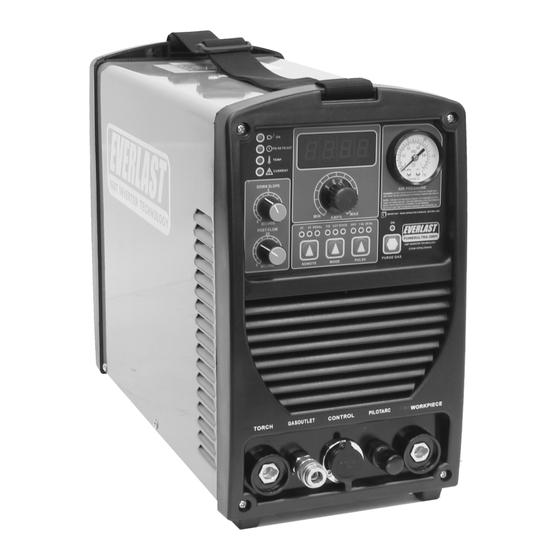
EVERLAST
POWERULTRA 206P
IGBT DC Multi-Process PulseTig/Stick/Plasma Cutter*
CC
GTAW-P
SMAW
PAC
1
~
PHASE
DC
DV
120/240V
Operator's Manual For The
DC Output PowerUltra 206Pi
Safety, Setup and General Use Guide
*
Not suitable for welding aluminum. Does not weld AC.
everlastwelders.com
1-877-755-9353
329 Littlefield Ave. South San Francisco, CA 94080 USA
i
Rev. 1
Specifications and Accessories subject to change without notice.
0 01010-16
Advertisement
Table of Contents
Troubleshooting

Related Manuals for Everlast PowerUltra 206Pi


Summary of Contents for Everlast PowerUltra 206Pi
- Page 1 IGBT DC Multi-Process PulseTig/Stick/Plasma Cutter* GTAW-P SMAW PHASE 120/240V Operator’s Manual For The DC Output PowerUltra 206Pi Safety, Setup and General Use Guide Not suitable for welding aluminum. Does not weld AC. Rev. 1 0 01010-16 everlastwelders.com Specifications and Accessories subject to change without notice.
-
Page 2: Table Of Contents
The owner of this product assumes all liability for its use and maintenance. Everlast Power Equipment INC. does not warrant this product or this document for fitness for any particular purpose, for performance/accuracy or for suitability of application. -
Page 3: Letter To The Customer
Dear Customer, THANKS! You had a choice, and you bought an Everlast. We appreciate you as a customer and hope that you will enjoy years of use from your welder. Please go directly to the Everlast website to register your unit and receive your warranty information. Your unit registration is important should any information such as product updates or recalls be issued. -
Page 4: Everlast Contact Information
Serial number: __________________________ Model number: ____________________________ Date of Purchase___________________________ Contact Information Everlast US: Everlast consumer satisfaction email: sales@everlastwelders.com Everlast Website: everlastwelders.com Everlast Technical Support: support@everlastwelders.com Everlast Support Forum: http://www.everlastgenerators.com/forums/index.php Main toll free number: 1-877-755 WELD (9353) 9am—5pm PST M-F 11am-4pm PST Sat. -
Page 5: Safety Precautions
Safety Precautions Everlast is dedicated to providing you with the best possible equipment and service to meet the demanding jobs that you have. We want to go beyond delivering a satisfactory product to you. That is the reason we offer technical support to assist you with your needs should an occasion occur. - Page 6 SAFETY PRECAUTIONS These safety precautions are for protection of safety and health. Failure to follow these guidelines may result in serious injury or death. Be careful to read and follow all cautions and warnings. Protect yourself and others. Welding and cutting processes produce high levels of ultraviolet (UV) radiation that can cause se- vere skin burn and damage.
- Page 7 SAFETY PRECAUTIONS WARNING! Persons with pacemakers should not weld, cut or be in the welding area until they consult with their physician. Some pacemakers are sensitive to EMF radiation and could severely malfunction while welding or while being in the vicinity of someone welding. Serious injury or death may occur! Welding and plasma cutting processes generate electro-magnetic fields and radiation.
- Page 8 SAFETY PRECAUTIONS continued WARNING! Electrical shock can kill. Make sure all electrical equipment is properly grounded. Do not use frayed, cut or otherwise damaged cables and leads. Do not stand, lean or rest on ground clamp. Do not stand in water or damp areas while welding or cutting. Keep work surface dry. Do not use welder or plasma cutter in the rain or in extremely humid conditions.
-
Page 9: Introduction And Specifications
No tungsten is provided. Extra consumables and full consumable kits may be purchased through Everlast or almost any local welding supply store for TIG. Plasma cutting consumables may be bought direct from Everlast or other online retailers. -
Page 10: Unit Specifications
Section 1 Introduction and Specifications POWERULTRA 206Pi INPUT/OUTPUT SPECIFICATIONS FEATURE/SPECIFICATION POWERULTRA 206Pi INVERTER TYPE IGBT, Digitally controlled INPUT VOLTAGE ±10%;PHASE/FREQUENCY 120/240V; 1PH/50-60Hz MAXIMUM INPUT AMPS (I₁MAX), Inrush. 30A @ 120V/ 28A @ 240V MAXIMUM INPUT RUNNING AMPS (I₁eff), Rated. 19A @ 120V/ 18A @ 240V... -
Page 11: General Overview
General overview: The new digitally controlled Power means that the unit is capable of being operated at the Ultra 206Pi from Everlast is a DC TIG, stick and plasma maximum amps for the stated percent of time out of 10 multi-purpose unit, designed for portable repair work and minutes without a cool down break. -
Page 12: Quick Setup Guide, Tig Torch/Cooler Connection
Section 2 QUICK SETUP AND USE GUIDE QUICK SETUP GUIDE: TIG CONNECTIONS TORCH (-) WORK (+) CONTROL PILOT ARC GAS (Ar) AIR-COOLED TORCH CONTROL 26 SERIES CONTROL FOOT PEDAL NOTE: Torch switch and foot pedal control cannot be connected at the same time. -
Page 13: Quick Setup Guide, Plasma Connection
When using the unit below 40 amps, the nozzles will need to be changed out for ones with a smaller diameter orifice. Everlast is the OEM supplier of the torch but not the manufacturer. Low amp cuts may be unstable unless the size is matched to the amps being used. -
Page 14: Quick Setup Guide, Stick Polarity And Connection
Section 2 QUICK SETUP AND USE GUIDE QUICK SETUP GUIDE: STICK POLARITY AND CONNECTIONS CONTROL PILOT ARC TORCH (+) WORK (-) NOTE: When changing from Stick to Plasma cutting or TIG, don’t for- get to change polarity of the torch and the work clamp. If polarity is not correct, welding and cutting problems will result. -
Page 15: Quick Setup Guide, Rear Connection For Plasma
Section 2 QUICK SETUP AND USE GUIDE QUICK SETUP GUIDE: REAR CONNECTIONS FOR PLASMA OPERATION Compressor and Dryer Diagram Compressor and Air hose w fittings (Customer Supplied) Regulator Assembly with built-in water trap and dirt filter (Included) 1/4” Automotive Universal style quick connector (Included) Connect for Plasma Use Only. -
Page 16: Quick Setup Guide, Rear Connection For Tig
IMPORTANT: Do not remove the installed 240V plug to use your welder on 120V. Use the supplied adapter. If you do not have an adapter, or have lost your adapt- er, you may purchase a 240V to 120V standard adapter from Everlast. INLET 240V to 120V adapter. -
Page 17: Front Panel Features And Controls
Section 2 QUICK SETUP AND USE GUIDE FRONT PANEL FEATURES AND CONTROLS 1. AMP DISPLAY 15. AIR PRESSURE GAUGE 2. ON/TEMP/O.C/OK-TO-CUT 3. DOWN SLOPE TIMER 14. AMP CONTROL 13. GAS PURGE 4. POST FLOW TIMER 5. 2T/4T PEDAL SWITCH 6. TIG/CUT/STICK SWITCH 7. - Page 18 If it does not, contact Everlast. The OK-TO-CUT LED will be lit when the unit has enough pressure to operate the plasma cutting torch safely. If this LED goes out, cutting will not be possible as the unit will stop output when it senses low air pressure.
- Page 19 Section 2 QUICK SETUP AND USE GUIDE FRONT PANEL FEATURES AND CONTROLS CONTINUED POWERULTRA 206Pi FEATURES PARAMETERS PURPOSE 8. Pilot Arc This connection is only to be used with the plasma cutting torch. The small ringed wire con- nects here. Unscrew the plastic thumb nut and attach the wire to the post. Reinstall the thumb nut over the wire with finger pressure only.
-
Page 20: Rear Panel Features And Controls
Section 2 QUICK SETUP AND USE GUIDE REAR PANEL FEATURES AND CONTROLS 1. POWER SWITCH 5. REGULATOR ASSY. 4. HF GROUND BOLT 2. POWER PLUG NEMA 6-50P INLET 3. GAS INLET GREEN GROUND (240V AND 120V ) L2 WHITE, HOT (240V) /NEUTRAL (120V) L1,BLACK;... - Page 21 NOTE: Never operate this unit on a generator that is not certified by its manufacturer to be “clean” power, which is typically less than 5% Total Harmonic Distorition (THD). Operating the unit on square wave output or modified sine wave generator is strictly prohibited. Contact the manufacturer of the generator for this information. Everlast does not have an “approved” list of genera- tors.
-
Page 22: Tungsten Preparation
Section 3 Basic theory and function TUNGSTEN PREPARATION 1. Use a dedicated grinding wheel or contamination may re- sult. Do not breath grinding dust! Wear eye protection and gloves. 2. Hold Tungsten firmly. 3. Grind perpendicular to grind- ing wheel face. Allow tungsten to grind away slowly, creating point. -
Page 23: Polarity, Tungsten And Amp Recommendations
Section 3 Basic theory and function GENERAL POLARITY RECOMMENDATIONS* *Follow manufacturer of stick electrode for complete polarity recommendations PROCESS TORCH POLARITY WORK POLARITY TIG (GTAW) STICK (SMAW) TIG (GTAW) OPERATION GUIDE FOR STEEL (ALUMINUM)* *As a general rule, set amperage using 1 amp for every .001” of metal thickness for aluminum. Less is required for DC. METAL THICKNESS WELDING AMPS TUNGSTEN DIA. -
Page 24: High Frequency Start Tig Operation
Section 3 Basic theory and function HIGH FREQUENCY START TIG OPERATION <1/8 <1/8” 1. Position the point of the sharpened tungsten about 1/8” or less above the metal. 2. Press the torch trigger or press the foot pedal to initiate the arc. The HF arc will be initiated. It may appear briefly as a blue spark. 3. -
Page 25: Stick Arc Starting Procedure
Section 3 Basic theory and function STICK OPERATION STARTING METHODS Scratch/Match Method Tapping Method 1. Turn on the power switch on the rear of the unit. Allow unit to cycle through its start up program. 2. Select the Stick mode with the TIG/Cut/Stick selector switch. 3. -
Page 26: Plasma Function And Operation
Use a .6mm nozzle for 20-25 amps, .8mm for 20-35amps, .9mm for 35-50 amps. Different sized consuma- bles are available from Everlast and many online or local sources. There is some overlap in nozzle cutting capacity, but minor fine-tuning of air pressure may help improve cut results. - Page 27 Section 3 Basic theory and function TIP: For longer consumable life do not use the pilot arc unnecessarily. Rapid wear will oc- cur if the pilot arc stays engaged more than 3 seconds at a time. FLAME AT FAST TRAVEL SPEED FLAME AT NORMAL TRAVEL SPEED TRAVEL TRAVEL...
- Page 28 Section 3 Basic theory and function AN EXAMPLE OF CUTTING A LEAD-IN WHEN CUTTING OUT A DISK SHAPED OBJECT AN EXAMPLE OF CUTTING A LEAD-IN WHEN CUTTING HOLE IN AN OBJECT When cutting an object, particularly a pattern shape, where the torch must pierce or re-fire in-line at an inter- section of a cut, a lead-in cut should be employed.
- Page 29 Section 3 Basic theory and function RESULTS OF CUT AT CORRECT SPEED, RESULTS OF CUT AT FAST SPEED AIR PRESSURE AND TORCH ANGLE ROUGH, DISTINCT CUT LINES SPACED FAR APART SMOOTH, EVEN CUT LINES WITH A S REARWARD SWEEP MINIMAL EASY TO CLEAN DROSS NOTICEABLE SMALL, HARD DROSS RESULTS OF TOO MUCH CURRENT OR RESULTS OF CUT AT SLOW SPEED...
- Page 30 If you are not sure about what size you need, contact Everlast. As a general rule, for each 10 amp unit of drop in am- perage below 40 amps, you will want to reduce orifice diameter by .1 mm. Not all orifice diameters and configurations are available from Evelast, but most can be bought from other sources.
-
Page 31: Expanded View Of Tig Torch
Section 3 Basic theory and function EXPANDED VIEW OF TIG TORCH (Actual appearance may vary slightly from what is listed.) 5/8” Parts for Standard 26 Series Torch ( 18 series uses same consuma- QTY. bles and basic design is similar, except water cooler line plumbing) Long Back Cap with O-Ring Short Back Cap Opt. -
Page 32: Expanded View Of Ag60 Plasma Torch
S-45 PLASMA TORCH** *Everlast is not the manufacturer of the Trafimet S-45 torch, nor is it affiliated with Trafimet. Trafimet and its logo are registered trademarks of Trafimet. Not all items, acces- sories and parts depicted are available directly through Everlast. These are items supplied through a number of nationwide Trafimet dealers and resalers. Diagram provided courtesy of Trafimet. -
Page 33: Pin Connector Pin-Out
Section 3 Basic theory and function 7 PIN CONNECTOR FOR FOOT PEDAL Bridge to 7 To Pedal or Torch Switch Bridge to 6 To Pedal or Torch Switch... -
Page 34: Troubleshooting
Check gas flow. Adjust for higher flow of gas. Listen for audible click of gas solenoid. If no click is heard, then contact Everlast Support. Clean weld properly, especially in Aluminum. Too short of post flow. Check tungsten stick out. -
Page 35: Trouble Shooting
Make sure swirl ring is not cracked. Arc will try to start if touched to the metal, but no air Stuck or dirty solenoid valve. Contact Everlast. Wrong Pro- flow while switch is pressed. cess selected.
Need help?
Do you have a question about the PowerUltra 206Pi and is the answer not in the manual?
Questions and answers