Table of Contents
Advertisement
Quick Links
EVERLAST
200DX
POWERTIG
CC
GTAW-P
SMAW
IGBT
1
~
PHASE
AC/DC
Operator's Manual for the PowerTig 200DX
Safety, Setup and General Use Guide
Rev. 4
0 00201-13
everlastwelders.com
Specifications and Accessories subject to change without notice.
1-877-755-9353
EVERLAST
329 Littlefield Ave. South San Francisco, CA 94080 USA
Advertisement
Table of Contents

Related Manuals for Everlast POWERTIG 200DX


Summary of Contents for Everlast POWERTIG 200DX
- Page 1 EVERLAST 200DX POWERTIG GTAW-P SMAW IGBT PHASE AC/DC Operator’s Manual for the PowerTig 200DX Safety, Setup and General Use Guide Rev. 4 0 00201-13 everlastwelders.com Specifications and Accessories subject to change without notice. 1-877-755-9353 EVERLAST 329 Littlefield Ave. South San Francisco, CA 94080 USA...
-
Page 2: Table Of Contents
The owner of this product assumes all liability for its use and maintenance. Everlast Power Equipment INC. does not warrant this product or this document for fitness for any particular purpose, for performance/accuracy or for suitability of application. -
Page 3: Letter To The Customer
Your unit registration is important should any information such as product updates or re- calls be issued. It is also important so that we may track your satisfaction with Everlast products and services. If you are unable to register by website, contact Everlast directly through the sales department through the main customer service number in your country. -
Page 4: Everlast Contact Information
Model number: ____________________________ Date of Purchase___________________________ EVERLAST Contact Information Everlast US: Everlast consumer satisfaction email: sales@everlastwelders.com Everlast Website: everlastwelders.com Everlast Technical Support: support@everlastwelders.com Everlast Support Forum: http://www.everlastgenerators.com/forums/index.php Main toll free number: 1-877-755 WELD (9353) 9am—5pm PST M-F 11am-4pm PST Sat. -
Page 5: Safety Precautions
Safe operation and proper maintenance is your responsibility. We have compiled this operator’s manual, to instruct you in basic safety, oper- ation and maintenance of your Everlast product to give you the best possible experience. Much of welding and cutting is based upon experience and com- mon sense. - Page 6 SAFETY PRECAUTIONS These safety precautions are for protection of safety and health. Failure to follow these guidelines may result in serious injury or death. Be careful to read and follow all cautions and warnings. Protect yourself and others. Welding and cutting processes produce high levels of ultraviolet (UV) radiation that can cause severe skin burn and damage.
- Page 7 SAFETY PRECAUTIONS WARNING! Persons with pacemakers should not weld, cut or be in the welding area until they consult with their physician. Some pacemakers are sensitive to EMF radiation and could severely malfunction while welding or while being in the vicinity of someone welding.
- Page 8 SAFETY PRECAUTIONS continued WARNING! Electrical shock can kill. Make sure all electrical equipment is properly grounded. Do not use frayed, cut or otherwise damaged cables and leads. Do not stand, lean or rest on ground clamp. Do not stand in water or damp areas while weld- ing or cutting.
-
Page 9: Introduction And Specifications
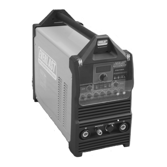
Section 1 Introduction and Specifications PowerTIG 200DX Water-cooled, 26 Series Torch Assembly 12 Ft (3 m) with built in 2T/4T switch (Style may vary) Argon Regulator Work Clamp Consumable Kit (Does not include Tungsten) 47K Ω Stick Electrode Holder Foot Pedal Assembly... -
Page 10: Unit Specifications
Section 1 Introduction and Specifications PowerTIG 200 DX TIG/Stick Welder Specification Standard 240 V /Optional Dual 120 V /240 V Process AC/DC GTAW-P/DC SMAW Inverter Type Analog, IGBT Construction Minimum/Maximum Rated Output TIG 240 V: DC: 5 A/10.2 V - 200 A/18V AC: 20 A/10.8 V - 200 A/18 V (Opt. -
Page 11: General Overview
General overview: The new, redesigned 200 DX Pulse- area or the force of the fan will cause welding issues such TIG/Stick welder from Everlast is the latest in a new gen- as unstable arc, or porosity. eration of analog style GTAW-P /SMAW inverter welders. -
Page 12: Quick Setup Guide, Tig Torch/Cooler Connection
Section 2 QUICK SETUP AND USE GUIDE QUICK SETUP GUIDE: TIG CONNECTIONS NOTE: Dual Voltage Model connections are the same in function but the gas connector location is on the far left and the work clamp. TORCH (-) WORK (+) CONTROL 35 SERIES CONNECTOR 35 SERIES CONNECTOR... -
Page 13: Quick Setup Guide, Stick Polarity
Section 2 QUICK SETUP AND USE GUIDE QUICK SETUP GUIDE: STICK POLARITY AND CONNECTIONS CONTROL TORCH (+) WORK (-) -
Page 14: Rear Panel Gas Connection And Wiring
AGE MODELS. DO NOT REMOVE THE PLUG. NO INTERNAL CHANGE IS RE- QUIRED TO OPERATE ON 120 V. THIS UNIT AUTOMATICALLY SENSES THE CHANGE IN SUPPLY POWER. TO PURCHASE AN ADAPTER CONTACT EVERLAST. EVERLAST NOTE: Use Ar or Ar/He only. Do not use more than 25% He in the Ar/He gas mix. -
Page 15: Front Panel Features And Controls
Section 2 QUICK SETUP AND USE GUIDE FRONT PANEL FEATURES AND CONTROLS 1. PROTECTIVE COVER 21. AMP DISPLAY 20. AMP CONTROL 2. 2T/PEDAL/ OR 4T SWITCH 19. ON/TEMP/O.C 18. HF/LIFT /STICK 17. ARC FORCE (DIG) 3. DOWN SLOPE (2T/4T) 16. SURGE AMPS * 15. - Page 16 Section 2 QUICK SETUP AND USE GUIDE FRONT PANEL FEATURES AND CONTROLS CONTINUED POWERTIG 200 DX FEATURES PARAMETERS PURPOSE 1. Protective Cover Clear hinged cover protects panel from damage. Keep closed during welding operations. 2. 2T/4T Sequencer Switch 2T -Pedal/4T Used with the torch switch function.
- Page 17 Everlast. Over Current Indicator: Lights up when a voltage /amp surge has sur- passed the units capabilities. Eliminate the source of the surge and manually cycle the power switch to reset.
-
Page 18: Rear Panel Features And Controls
Section 2 QUICK SETUP AND USE GUIDE REAR PANEL FEATURES AND CONTROLS 1. WATER COOLER RECEPTACLE 5. 3-POLE POWER SWITCH 220/240 V WATER COOLER ONLY! 1~220 VAC 4. POWER CABLE 1 ~ 220/240V 1~220 V INLET 2. HF GROUND BOLT 3. - Page 19 Less than 5% is preferred. Operating the unit on square wave output or modified sine wave generators is strictly prohibited. Contact the manufacturer of the generator for this information. Everlast does not have an “approved” list of generators. But, if the generator is not listed as clean power by its manufacturer, then operation is prohibited.
-
Page 20: Welder Function Summary And Explanations
Section 3 Basic theory and function Welder Function Summary and Explanations. The 2T/4T section on the welder panel are devoted to the use of the 2T/4T operation and should not be used 1. 2T/4T sequencer. The 2T/4T feature allows op- with foot pedal. - Page 21 Section 3 Basic theory and function Cleaning/Frosted Area of Aluminum running parallel to the side of the weld. Not all weld conditions will be alike, so more cleaning is 30% EP required at times than others. Similarly, more pen- Narrow bead/etching/sharp tungsten etration will be required at times than others.
- Page 22 Section 3 Basic theory and function 5. Pulse. The pulse creates two amp values, a high EXAMPLE 1 and a low value that cycle back and forth between Welding Amps: 100 amps, each other while welding. The upper amperage is PulseAmps: 50% called the “welding amps”...
- Page 23 The foot need a new one for your torch or damage yours, consult Everlast. Do not use a nipple that is scarred, bent or other- pedal also controls both Welding Amps, and Pulse Amps through the ratio established by selecting the wise deformed.
-
Page 24: Tungsten Preparation
Section 3 Basic theory and function TUNGSTEN PREPARATION 1. Use a dedicated grinding wheel or contamination may re- sult. Do not breath grinding dust! Wear eye protection and gloves. 2. Hold Tungsten firmly. 3. Grind perpendicular to grind- ing wheel face. -
Page 25: Lift Start And High Frequency Start
Section 3 Basic theory and function LIFT START TIG OPERATION Note: A Lift TIG start should be done with a nearly seamless motion. Use a light touch and a quick motion for best results. FOR DC USE. NOT RECOMMENED FOR AC. <1/8”... -
Page 26: Stick Starting Methods
Section 3 Basic theory and function STICK OPERATION STARTING METHODS Scratch/Match Method Tapping Method 1. Turn on the power switch on the rear of the unit. Allow unit to cycle through its start up program. 2. Select the Stick mode with the HF/Lift Start/Stick selector switch. 3. -
Page 27: Recommendations For Polarity/Amps/Tungsten
Section 3 Basic theory and function GENERAL POLARITY RECOMMENDATIONS* *Follow manufacturer of stick electrode for complete polarity recommendations PROCESS TORCH POLARITY WORK POLARITY TIG (GTAW) STICK (SMAW) TIG (GTAW) OPERATION GUIDE FOR STEEL (ALUMINUM)* *As a general rule, set amperage using 1 amp for every .001” of metal thickness for aluminum. Less is required for DC. METAL THICKNESS WELDING AMPS TUNGSTEN DIA. -
Page 28: Expanded View Of Tig Torch
Section 3 Basic theory and function EXPANDED VIEW OF TIG TORCH (Actual appearance may vary slightly from what is listed.) 5/8” PARTS FOR 26 Series Torch ( STYLE MAY VARY) QTY. Long Back Cap with O-Ring Short Back Cap Opt. Torch Head Insulator Collet 1/16 or 3/32... -
Page 29: Pin Connector Pin-Out
Section 3 Basic theory and function 7 PIN CONNECTOR FOR 47K Ω FOOT PEDAL AND REMOTE AMP CONTROLLER ON OPTIONAL TORCH Bridge to 7 To Pedal or Torch Switch Bridge to 6 To Pedal or Torch Switch... -
Page 30: Troubleshooting
Check gas flow. Adjust for higher flow of gas. Listen for audible click of gas solenoid. If no click is heard, then contact Everlast Support. Clean weld properly, especially in Aluminum. Too short of post flow. Check tungsten stick out.
Need help?
Do you have a question about the POWERTIG 200DX and is the answer not in the manual?
Questions and answers