Table of Contents
Advertisement
EVERLAST
POWERTIG 255 EXT
Digital AC/DC TIG/STICK WELDER
CC
GTAW-P
SMAW
IGBT
DV
120/240V
AC/DC
Operator's Manual for the PowerTig 255 EXT
everlastwelders.com
GTAW/SMAW
Safety, Setup and General Use Guide
1-877-755-9353
329 Littlefield Ave. South San Francisco, CA 94080 USA
Rev.2
Specifications and Accessories subject to change without notice.
0 021212-14
Advertisement
Table of Contents

Related Manuals for Everlast Powertig 255 EXT


Summary of Contents for Everlast Powertig 255 EXT
- Page 1 Digital AC/DC TIG/STICK WELDER GTAW/SMAW GTAW-P SMAW IGBT 120/240V AC/DC Operator’s Manual for the PowerTig 255 EXT Safety, Setup and General Use Guide Rev.2 0 021212-14 everlastwelders.com Specifications and Accessories subject to change without notice. 1-877-755-9353 329 Littlefield Ave. South San Francisco, CA 94080 USA...
-
Page 2: Table Of Contents
The owner of this product assumes all liability for its use and maintenance. Everlast Power Equipment INC. does not warrant this product or this document for fitness for any particular purpose, for performance/accuracy or for suitability of application. -
Page 3: Letter To The Customer
Your unit registration is important should any information such as product up- dates or recalls be issued. It is also important so that we may track your satisfaction with Everlast products and services. If you are unable to register by website, contact Everlast directly through the sales department through the main customer service number in your country. -
Page 4: Everlast Contact Information
Model number: ____________________________ Date of Purchase___________________________ EVERLAST Contact Information Everlast US: Everlast consumer satisfaction email: sales@everlastwelders.com Everlast Website: everlastwelders.com Everlast Technical Support: support@everlastwelders.com Everlast Support Forum: http://www.everlastgenerators.com/forums/index.php Main toll free number: 1-877-755 WELD (9353) 9am—5pm PST M-F 11am-4pm PST Sat. -
Page 5: Safety Precautions
Safe operation and proper maintenance is your responsibility. We have compiled this operator’s manual, to instruct you in basic safety, oper- ation and maintenance of your Everlast product to give you the best possible experience. Much of welding and cutting is based upon experience and com- mon sense. - Page 6 SAFETY PRECAUTIONS These safety precautions are for protection of safety and health. Failure to follow these guidelines may result in serious injury or death. Be careful to read and follow all cautions and warnings. Protect yourself and others. Welding and cutting processes produce high levels of ultraviolet (UV) radiation that can cause severe skin burn and damage.
- Page 7 SAFETY PRECAUTIONS WARNING! Persons with pacemakers should not weld, cut or be in the welding area until they consult with their physician. Some pacemakers are sensitive to EMF radiation and could severely malfunction while welding or while being in the vicinity of someone welding.
- Page 8 SAFETY PRECAUTIONS continued WARNING! Electrical shock can kill. Make sure all electrical equipment is properly grounded. Do not use frayed, cut or otherwise damaged cables and leads. Do not stand, lean or rest on ground clamp. Do not stand in water or damp areas while weld- ing or cutting.
-
Page 9: Introduction And Specifications
Introduction and Specifications PowerTIG 255EXT Accessories Accessory 20 Series TIG torch and cable 9 Series TIG torch and cable Everlast 47k Ω Pedal Heavy duty work clamp Heavy duty electrode holder Regulator and hose assy. 240 to 120V Pigtail adapter... -
Page 10: Unit Specifications
Section 1 Introduction and Specifications PowerTIG 255EXT/325 EXT TIG/Stick Welder Specification Process AC/DC GTAW-P/DC SMAW Inverter Type Digital Microprocessor Controlled, IGBT Module Minimum/Maximum Rated Output TIG 120V: DC 3 A/10.1V-150A/16V AC: 5A/10.2-150A/16V 240V: DC 3 A/10.1V- 250 A/20V AC 5 A/10.2V- 250 A/20V Minimum/Maximum Rated Output Stick 120V: 20A-120A/20.8V-24.8V 240V: 20 A/20.8V - 225 A/29V... -
Page 11: Product Overview
18”. Do digitally controlled, inverter welders from Everlast. not operate the welder immediately in the weld area or With a microprocessor and IGBT module design, the... -
Page 12: Quick Setup Guide, Tig Torch/Cooler Connection
Section 2 QUICK SETUP AND USE GUIDE QUICK SETUP GUIDE: TIG CONNECTIONS TORCH (-) 9/17 SERIES TORCH WORK (+) CONTROL 35 SERIES CONNECTOR 35 SERIES CONNECTOR AIR-COOLED TORCH GAS (Ar) CONTROL CONTROL 26 SERIES TORCH FOOT PEDAL 35 SERIES CONNECTOR GAS (Ar) CONTROL WATER-COOLED TORCH... -
Page 13: Quick Setup Guide, Stick Polarity
Section 2 QUICK SETUP AND USE GUIDE QUICK SETUP GUIDE: STICK POLARITY AND CONNECTIONS CONTROL TORCH (+) WORK (-) -
Page 14: Rear Panel Gas Connection And Wiring
CONTACT EVERLAST TO PURCHASE AN ADAPTER IF NEEDED. AC 120V GREEN GROUND AC 220V 120V/220V COOLER OUTLET. RECOMMENDED FOR DUAL VOLT- AGE EVERLAST POWERCOOL WC 300 ONLY. WARNING: DO NOT USE THIS OUTLET FOR ANY OTHER APPLICATION OR SERVICE! L2,WHITE L1,BLACK; HOT NEMA 6-50P... -
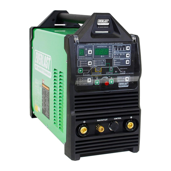
Page 15: Front Panel Features And Controls
Section 2 QUICK SETUP AND USE GUIDE FRONT PANEL FEATURES AND CONTROLS POWERTIG 255EXT 1. CLEAR PROTECTIVE PANEL COVER 2. CONTROL PANEL GAS OUTLET CONTROL 6. POSITIVE CONNECTOR 3. NEGATIVE CONNECTOR DINSE 35-70mm² DINSE 35-70mm² 4.GAS OUTLET 9MM QUICK CONNECT 5. - Page 16 Section 2 QUICK SETUP AND USE GUIDE FRONT PANEL FEATURES AND CONTROLS POWERTIG 255EXT POWERTIG 255 EXT PARAMETERS PURPOSE MAIN PANEL FEATURES 1. Protective Cover Clear hinged cover protects panel from damage. Keep closed during welding opera- tions. 2. Main Control Panel Digital The main control features digital adjustment.
-
Page 17: Front Panel Features And Controls 255Ext/325Ext
Section 2 QUICK SETUP AND USE GUIDE FRONT PANEL FEATURES AND CONTROLS POWERTIG 255EXT/325EXT POWERTIG 255EXT/325EXT PARAMETERS PURPOSE 1. Memory Function The unit has 9 programs which allow the operator to select parameters and hen save the settings to the selected program channel. To operate, use the selector button to select the desired program number where the program is to be assigned. - Page 18 Section 2 QUICK SETUP AND USE GUIDE FRONT PANEL FEATURES AND CONTROLS POWERTIG 255EXT/325EXT POWERTIG 255EXT/325EXT PARAMETERS PURPOSE 5. Upslope 0-25 Seconds Upslope ramps “up” from the start amp value to the welding amp value while starting the weld puddle. For best operation, the value will be automatically be set to 0 with standard foot pedal mode.
- Page 19 Section 2 QUICK SETUP AND USE GUIDE FRONT PANEL FEATURES AND CONTROLS POWERTIG 255EXT/325EXT POWERTIG 255EXT/325EXT PARAMETERS PURPOSE 12. Down Slope 0-25 Seconds Down Slope will ramp amps “down” from the welding amp value to the end amp value to give time to fill the crater left at the end of the weld bead.
- Page 20 Section 2 QUICK SETUP AND USE GUIDE FRONT PANEL FEATURES AND CONTROLS POWERTIG 255EXT/325EXT POWERTIG 255EXT/325EXT PARAMETERS PURPOSE 21. 2T/4T/ Pedal Selector 2T, 4T, Pedal, This selects the operation of the torch switch, pedal, or hand amptrol. To weld with the torch Pedal with 2T, switch, select 2T or 4T.
-
Page 21: Rear Panel Features And Controls
Section 2 QUICK SETUP AND USE GUIDE REAR PANEL FEATURES AND CONTROLS 255EXT 1. WATER COOLER RECEPTACLE. 5. 2-POLE POWER SWITCH DUAL VOLTAGE 1~110 VAC 1~220 VAC 4. POWER CABLE 110/220V 1~110 V INLET 1~220v 2. HF GROUND BOLT 3. ARGON GAS INLET... - Page 22 If bubbles are seen, retighten. 4. Power Cord 110/220 V 1 phase The PowerTIG 255 EXT operates on 110V/220V power(±10%). The unit uses a NEMA 6-50 (120V/240V) plug for 220V power. This is a standard plug designated for welder use. NOTE: There is NO neutral in a standard 220V welder circuit.
-
Page 23: Welder Function Summary And Explanations
END AMPS POST FLOW PREFLOW = UP ON SWITCH Everlast 26 series hand amptrol torch = DOWN ON SWITCH 2. Easy Start Modes (AC and DC). The unit is equipped with a separate AC and DC easy start mode. This... - Page 24 Section 3 Basic theory and function have little or no way to change the ratio of EN to EP, 3. AC Wave Forms. The wave form control is a which results in welding with a molten ball at the tip useful feature for achieving a desired type of arc of the tungsten and a less stable arc.
- Page 25 Section 3 Basic theory and function EXAMPLE: AC EP (+) BALANCE Parameter Notes: 1 Hz (one full AC cycle) EP 50% EN 50% Standard transformer welder balance: 50% EN/EP Balling tungsten, light penetration, wide cleaning area. EP 65% EN 35% Extreme cleaning setting.
- Page 26 Section 3 Basic theory and function 6. Standard Pulse. (AC and DC) The pulse creates two EXAMPLE 1 amp values, a high and a low value that cycle back and Welding Amps: 100 amps, forth between each other while welding. The upper PulseAmps: 50% amperage is called the “welding amps”...
- Page 27 The Power Cool 300 may be purchased separately from graph below has been simplified for clarity. It is de- Everlast which is designed to cool the torch up to the maxi- signed to show the relationship and interaction be- mum amp capacity of the welder. If you are not have a...
- Page 28 Should you need a new one for your torch or damage yours, consult Everlast. Do not use a nipple that is scarred, bent or otherwise deformed. Damage to the female connector may result. Serious leaks may occur.
-
Page 29: Tungsten Preparation
Section 3 Basic theory and function TUNGSTEN PREPARATION 1. Use a dedicated grinding wheel or contamination may re- sult. Do not breath grinding dust! Wear eye protection and gloves. 2. Hold Tungsten firmly. 3. Grind perpendicular to grind- ing wheel face. Allow tungsten to grind away slowly, creating point. -
Page 30: Lift Start And High Frequency Start
Section 3 Basic theory and function LIFT START TIG OPERATION Note: A Lift TIG start should be done with a nearly seamless motion. Use a light touch and a quick motion for best results. FOR DC USE. NOT RECOMMENED FOR AC. <1/8”... -
Page 31: Stick Starting Methods
Section 3 Basic theory and function STICK OPERATION STARTING METHODS Tapping Method Scratch/Match Method 1. Turn on the power switch on the rear of the unit. Allow unit to cycle through its start up program. 2. Select the Stick mode or Stick VRD with the HF/Lift Start/Stick/ VRD selector button 3. -
Page 32: Recommendations For Polarity/Amps/Tungsten
Section 3 Basic theory and function GENERAL POLARITY RECOMMENDATIONS* *Follow manufacturer of stick electrode for complete polarity recommendations PROCESS TORCH POLARITY WORK POLARITY TIG (GTAW) STICK (SMAW) TIG (GTAW) OPERATION GUIDE FOR STEEL (ALUMINUM)* *As a general rule, set amperage using 1 amp for every .001” of metal thickness for aluminum. Less is required for DC. METAL THICKNESS WELDING AMPS TUNGSTEN DIA. -
Page 33: Expanded View Of Tig Torch
Section 3 Basic theory and function EXPANDED VIEW OF TIG TORCH (Actual appearance may vary slightly from what is listed.) 5/8” TYPICAL PARTS FOR 9/20 Series Torch ( STYLE MAY VARY) QTY. Long Back Cap with O-Ring Short Back Cap Opt. -
Page 34: Pin Connector Pinout
Section 3 Basic theory and function 7 PIN CONNECTOR FOR 47K Ω FOOT PEDAL Bridge a Jumper to Pin 7 To Pedal or Torch Switch ON/OFF Bridge a Jumper to Pin 6 To Pedal or Torch Switch ON/OFF Middle High Potentiometer (VR) Foot Pedal (47/50k Ω) -
Page 35: Troubleshooting
Check gas flow. Adjust for higher flow of gas. Listen for audible click of gas solenoid. If no click is heard, then contact Everlast Support. Clean weld properly, espe- cially in Aluminum. Too short of post flow time. Check tungsten stick out. -
Page 36: Trouble Codes
Check foot pedal for complete return or stuck micro-switch. Do not hold down the switch or pedal without attempting to strike an arc. Doing so for more than 2 seconds without starting will cause this error code. OTHER CONTACT EVERLAST... - Page 37 Notes:...
Need help?
Do you have a question about the Powertig 255 EXT and is the answer not in the manual?
Questions and answers