Table of Contents
Advertisement
Publish Date: DEC. 2023
EVHCANE220MTSC Rev. 1
USA/North America
©Everlast Power Equipment
DC
225A
AC/DC
225A
DC
160A
DC
40A
120/240V
Welders, Plasma Cutters, Multi-Process
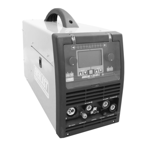
Safety, Setup and General Use Guide For The
Hurricane 220 MTS-C
Operator's Manual
FUNCTION: MIG/ AC/DC Pulse TIG/DC Stick/Plasma Cutter
PURCHASE DATE:
MODEL NAME:
SERIAL NUMBER:
OPTIONAL ACCESSORY SERIAL NUMBER:
Advertisement
Table of Contents

Related Manuals for Everlast Hurricane 220 MTS-C


Summary of Contents for Everlast Hurricane 220 MTS-C
- Page 1 Publish Date: DEC. 2023 EVHCANE220MTSC Rev. 1 USA/North America ©Everlast Power Equipment Safety, Setup and General Use Guide For The 225A Hurricane 220 MTS-C AC/DC 225A 160A FUNCTION: MIG/ AC/DC Pulse TIG/DC Stick/Plasma Cutter PURCHASE DATE: MODEL NAME: SERIAL NUMBER: OPTIONAL ACCESSORY SERIAL NUMBER: Operator’s Manual...
-
Page 2: Table Of Contents
SAFETY WARNINGS, DANGERS, CAUTIONS AND INSTRUCTIONS GENERATOR OPERATION INFORMATION/DUAL VOLTAGE INFORMATION SPECIFICATIONS DUTY CYCLE INFORMATION PRODUCT SPECIFICATIONS FOR HURRICANE 220 MTS-C GETTING STARTED, UNPACKING YOUR UNIT AND INSPECTION CONNECTING YOUR UNIT TO THE POWER SOURCE AND WIRING INFORMATION CONNECTION OF AIR COMPRESSOR, REGULATORS... -
Page 3: Special Notice And California Proposition 65 Warning
Due to multiple variables that exist in the welding field and the changing nature of it and of the Everlast product line, Everlast Power Equipment INC. does not guarantee the accuracy, completeness,... -
Page 4: Customer Greeting And Explanation Of Procedures
Many issues can be resolved over the phone. If the issue cannot be resolved over the phone/email, you may be given an op- tion to return the unit, or have a part shipped to you, at Everlast’s discretion. Keep in mind, you may be asked questions that seem basic, or ele- mentary to your knowledge base. -
Page 5: Warranty And Contact Information
Warranties and service policies and procedures vary from country to country and are maintained and supported by the region- al or in country distributor of Everlast welding equipment. USA Customers Only: For full details on the 5 year parts and labor warranty, 30 day satisfaction policy, terms of sale, and how to proceed with a war- ranty claim, please visit: https://www.everlastgenerators.com/standard-warranty. -
Page 6: Safety Disclaimer And Hf Warning
Safe operation and proper maintenance is your responsibility. Everlast is dedicated to keeping safety a top priority. While we have compiled this operator’s manual to instruct you in basic safe operation and maintenance of your Everlast product, it is no substitute for observing safe welding practices and behavior. Safe welding and related cutting operations require basic knowledge, experience and ultimately the exercise of common sense. -
Page 7: Safety Warnings, Dangers, Cautions And Instructions
If you or the operator needs further instruction, contact Everlast welding sup- port at 1-877 755-9353 ext. 204 or seek qualified professional advice and training. - Page 8 Safety Warnings, Dangers, Cautions and Instructions DANGER! Welding and cutting operations pose serious inhalation hazards. Some of these hazards are immediate while others are cumulative in their effect. Do not weld in enclosed spaces or in areas without adequate ventilation. Fumes and gases released in the welding and cutting operations can be toxic.
- Page 9 Safety Warnings, Dangers, Cautions and Instructions CAUTION! Trip Hazards exist around this unit. Cords, cables, welding leads and hoses pose a trip hazard. Be aware of their location and inform others of their location. Tape and secure them so they will stay out of high traffic areas. CAUTION! Welded metal can stay hot long after welding is completed.
-
Page 10: Generator Operation Information/Dual Voltage Information
REAR OUTLET WARNING! If equipped, never use the electrical power outlet on the back of this machine for anything other than powering an Everlast brand water cooler. This is a special outlet designed to produce 240V with limited amperage draw. No other device or brand should be used in con- junction with this unit’s outlet. -
Page 11: Specifications
Specifications Duty Cycle Duty Cycle is simply the amount of time out of a 10 minute period in which the unit can operate. For example, if this unit has a duty cycle of 25% at maximum rated output means that the unit can be operated for 2.5 minutes out of 10 minutes at the maximum rated Volt/Amp settings. - Page 12 Use the I1MAX and the I1EFF ratings listed above to determine the proper breaker and conductor (wire) sizing required. Everlast plasma cutters are designed around use in industrial wiring applications and are intended to be used with modern electrical systems.
-
Page 13: Product Specifications For Hurricane 220 Mts-C
Specifications Hurricane 220 MTS-C Product Specifications Construction Type Inverter (IGBT based, Digital Control) Input Voltage 120V OR 240 V (± 10%) 50/60 Hz Auto-Adjusting Phase 1 Phase 50/60Hz I1MAX Current Rating (Inrush Amps) 120V: 28A 240V: 31A I1EFF Current Rating (Rated Amps) 120V: 17A 240V: 16A 64V MIG/ Stick;... - Page 14 Setup Guide WARNING! Do not leave more than one torch connected at the same time. Leaving multiple torches connected at the same time may result in accidental arcing, and personal injury, or shock. Machine damage may also occur. Do not touch the connector ter- minals while the unit is on.
-
Page 15: Getting Started, Unpacking Your Unit And Inspection
Everlast. See page 5 for more contact information. NOTICE: Cosmetic 24 Series MIG Gun/Torch. damage claims after 30 days will not be accepted, unless Everlast is con- 250A Work Clamp (approx. 9.5 ft with cable). tacted and informed of such delay and reason for such a required delay 250A Stick Electrode Holder (approx. -
Page 16: Connecting Your Unit To The Power Source And Wiring Information
Do not wire connections for this machine if you are not the display screen will reflect the power input mode with one of the center qualified. Everlast is in no way liable for any damages caused by tree information boxes displaying “120V”. To change back to 240V input, improper connection of this unit. - Page 17 However, you will need to sup- ble/parts bag to connect the tubing to the regulator and fittings. If missing, contact Everlast. Make sure the air flow direction is correct ply a few things on your own.
-
Page 18: Connection Of Air Compressor, Regulators
The Hurricane 220 MTS-C is a synergic unit which incorporates the type of gas and metal wire being welded with as a base to make accu- Connect the regulator tubing to the regulator. -
Page 19: Torch Polarity And Accessory Connections
If the MIG gas regulator is leaking, discontinue use and contact Holder Everlast technical support. Do not attempt to modify or repair this regula- tor. If the air regulator is leaking, make sure the pressure is not more than 90 psi, and tighten the small screws on the regulator with a screw driver. - Page 20 Setup Guide Getting Started SELECT THE CORRECT MIG AND FLUX-CORED POLARITY. How Do I Change Polarity For Flux-Cored? Even though similar in concept, MIG/MAG (GMAW) and Gas-less Flux-Cored (FCAW) welding require a polarity change when transitioning between the two. The unit will remind you with an on-screen prompt to change polarity when you change between the processes, but this is an often over-looked issue, even Flux-Cored when reminded by the machine.
-
Page 21: Installing The Mig Wire And Spool Gun Connection
Setup Guide Getting Started INSTALLING THE OPTIONAL SPOOL GUN. How Do I Select TIG Polarity? The Parker DSP 360A Spoolgun is recommended for use with this unit and provides the best duty cycle and amperage rating. The SM200N may also be used but is rated for an Amperage and duty cycle that is lower than AC or DC the machine, which may lead to shortened gun and consumable life. - Page 22 Setup Guide Getting Started drive roll. Install the drive roll with the size stamp facing the inside. CHECK AND CHANGE YOUR DRIVE ROLL. The unit comes equipped with .030” and .035” drive rolls and 4 roll . INSTALL THE WIRE AND FEED THE GUN. NOTICE: For most purposes up to 3/16”...
- Page 23 Setup Guide Getting Started To Tension the drive roll and check for proper wire feeding: TRIM THE WIRE AFTER INSTALLATION. Trim the wire sticking out of the nozzle to 1/4” to 3/8” (6mm to 9mm) in • Turn the unit on and pull the trigger so that the wire extends approxi- length with wire cutters.
-
Page 24: Front Panel View And Component Id
Component Identification and Explanation Front Panel View Number Component Identification Component Note Protective Cover Keep cover down and in place during welding activities and in storage. Euro-Style Quick Connector Connect to the MIG gun or Spool Gun. The MIG gun and the spool gun share the same connection. Positive Terminal (+) For Stick, connect to the Torch. -
Page 25: Rear Panel View And Component Id
An aftermarket inert gas flow valve and 5/8 CGA fittings may be sourced locally or online to allow both to be connected simultaneously if desired, however Everlast does not supply these fittings or offer kits to do so. -
Page 26: Control Panel Layout
The left adjustment knob is used change the desired status of a function (i.e. voltage, turn on/off, electrode type, thickness etc.) and to set all Left Adjustment adjustable values to the left side of the black dividing hash mark just above the “EVERLAST” logo. If you push in on the knob while adjusting, it Knob will adjust in larger increments, usually in whole numbers or increments of 10. -
Page 27: Getting Ready To Weld/General Information And Use
Component Identification and Explanation Getting Ready To Weld ter selection, the machine automatically defaults back to the main parame- GENERAL INFORMATION ON SETUP AND USE. ter area and the numbers will brighten and will be able to be adjusted. Of course, if you continue to navigate completely through the left or right side functions and parameters, you will eventually cycle back to the default parameter area ( voltage, wire speed, amperage etc.) and the numbers will... - Page 28 Component Identification and Explanation Getting Ready To Weld PRGRM/SAVE/RECALL button to return to the program screen. Use the navigation buttons to highlight the desired program. Quickly press and release the PRGRM/SAVE/RECALL button to recall and open the program. If the program needs to be fine tuned, the settings may be adjusted or changed while in use.
-
Page 29: Setting Up The Unit For Welding And Cutting Manually
Component Identification and Explanation Setting the Unit Up for Welding/Cutting Manually sure to wait until this screen is present before you attempt any change of The Welcome/Boot Screen the welding process. Any time you change processes, the screen will reappear briefly to remind you to make any required changes to polarity. THE MAIN CONTROL SCREENS (MANUAL MODE) The MIG/Flux Cored Manual Screen When you first turn the unit on with the rear power switch, this screen will... - Page 30 Component Identification and Explanation Setting the Unit Up for Welding/Cutting Manually side. After 5 seconds of adjustment or no input being made, When also serves to provide gun cooling. However, the user may opt to the Wire Feed Speed is selected for adjustment the display will turn down this setting if desired Use the left Up and Down navigation brighten in color.
- Page 31 Component Identification and Explanation Setting the Unit Up for Welding/Cutting Manually 4T mode in which case the trigger will be pressed and released and Amperage setting after 4 to 5 seconds. the cycle will begin. A second press of the trigger will be required to Arc Force %.
- Page 32 Component Identification and Explanation Setting the Unit Up for Welding/Cutting Manually increase supply hose diameter. Do not supply more than 90 psi to the rear regulator from the air compressor. If needed, the plasma cutter may be operated with Nitrogen gas with a high flow regulator. Air Pressure.
- Page 33 Component Identification and Explanation Setting the Unit Up for Welding/Cutting Manually welded with DC unless it is an Aluminum or Magnesium, or an alloy The Manual AC/DC TIG Screen thereof. Stainless, Bronze, Up and Down Slope. Up and Down Slope provide a ramping up or down of the welding Amperage from the Starting or Ending Amp Setting.
- Page 34 Component Identification and Explanation Setting the Unit Up for Welding/Cutting Manually Amp stage of the pulse. This is the highest Amperage stage of the will cycle on and will ramp automatically to the Welding Amp Selec- pulse. This is also referred to as the “Peak” Amperage. The second tion set on the machine.
-
Page 35: Setting Up The Powerset Mode
Component Identification and Explanation Setting the Unit Up in The PowerSet Mode Using PowerSet Mode. UNDERSTANDING POWERSET. The PowerSet mode, regardless of process selected is designed to help the user make accurate settings without the aid of complicated charts or calculators. - Page 36 Component Identification and Explanation Setting the Unit Up PowerSet Mode back at the suggested setting, the white 4 pointed star will reappear. Keep in mind these are suggested setting only. The unit is designed so the user can adjust the functions up or down freely until the limit is reached to achieve desirable results.
-
Page 37: 4T General Operation Information
Component Identification and Explanation NOTICE: The following sections cover MIG, TIG, Stick, and Plasma terms, definitions, and basic opera- tion. Some of the terms overlap from process to process and serve essentially the same functions. Take note that some terms will repeat from process to process, but will be de- scribed in a way that is specific to the process being used. - Page 38 Component Identification and Explanation Using The Trigger/Torch Switch Remote Functions Operating the 2T/4T Remote Function The Remote Torch Trigger function works with both the MIG and TIG pro- cesses. The Trigger function is designed to allow the user to program the welder so that the stages of the weld cycle can be controlled via operation of the torch switch.
-
Page 39: Explanation Of Mig Functions And Terms
Component Identification and Explanation Explanation of MIG Functions and Terms EXPLANATION OF WELDER FUNCTIONS bacon should be heard. The actual frying sound can vary somewhat and may have somewhat of a higher pitch whine to it. If these sounds are Volt and Amp Settings present, look at the arc to see if it is steady, and producing low amounts of spatter. - Page 40 Component Identification and Explanation Explanation of MIG Functions and Terms well versed in MIG quickly develop a sense of when to push and when to prep the metal sufficiently to remove oxidation and paint. However, to pull the gun. Even for novices, a sense of when to push and pull the gun remove grease a degreaser such as acetone should be used.
- Page 41 Component Identification and Explanation Explanation of MIG Functions and Terms Joint Preparation What Are the Different Kinds of Welds? Besides a butt joint (Flat edge to flat edge) and lap joint (overlapping V-GROOVE (60-80°) DOUBLE V-GROOVE edges) which are often used for thinner metal gauges, consider using one of these groove joints for best welding results.
- Page 42 Component Identification and Explanation Explanation of MIG Functions and Terms MIG Welding is fairly simple if you keep travel angle and direction in mind when welding. See below. If you are welding flux- core, the gun direction is reversed. Remember: If it has gas, you use a push angle. If it is gas-less you use a drag angle. The old welder’s saying “If it has slag, you drag.”...
-
Page 43: Mig Torch Component Breakdown And Parts/Consumables (North 24 Series)
Component Identification and Explanation North 24 Series MIG Gun... -
Page 44: Explanation Of Tig Functions And Terms
Cleaning/Etched Area of Aluminum tive. So what would be a “safe” 30% electrode positive setting on the Ever- last, becomes a 70% electrode negative setting on other brands. Everlast, along with other brands has chosen this way polarity orientation since the... - Page 45 Component Identification and Explanation Explanation of TIG Functions and Terms AC Frequency. AC frequency is the number of times per second that the Negative Amps if Independent Amplitude is selected) to the End Amp set- AC completely cycles between positive and negative polarity. Frequency is ting.
- Page 46 “Pulse Amps” (sometimes called “background” If you need this type of start on a welder, contact Everlast for other product or “base” current). The Pulse Amps are set as a percent value of Welding information.
- Page 47 Component Identification and Explanation Explanation of TIG Functions and Terms lect the best operation. Even then none of them may be suitable for the bead profile will change and additional control will be given. user, depending upon personal preferences, skill and understanding of the Is There a Better Way to Understand Pulse? pulse.
- Page 48 Component Identification and Explanation Explanation of TIG Functions and Terms the starting point, at which the arc initiates. The Start Amps may vary de- What Are The Adv. AC Pulse Components? pending upon the type remote used and upon the Tungsten dimeter. Advanced AC Pulse is a mix of both AC and DC.
- Page 49 Component Identification and Explanation Explanation of TIG Functions and Terms Tungsten as rapidly, but some “heat” loss going into the weld will be ex- perienced. If used in the Split wave form configuration, it offers good utility when used with other wave forms on both EN– and EP+ sides of the wave form.
-
Page 50: Tig Torch Component Breakdown And Parts/Consumables (26 Series Air Cooled Torch)
26 Series Air-Cooled Welding Torch (Typical Type) Parts and Assembly. DC: 200A @ 60% Duty Cycle; AC: 175A @ 60% Duty Cycle Typical Everlast and NOVA Torch Assembly (17,18, 26 Series) (Some parts may not appear exactly the same but are equal in assembly order and type.) Tungsten not included, but available in select Consumable Kits on the website at www.everlastwelders.com. -
Page 51: Tungsten Selection And Shaping
Component Identification and Explanation Purchasing Tungsten can be difficult. Local suppliers tend to put a premi- SELECT THE PROPER TUNGSTEN TYPE. um price on Tungsten, and may be three times an online price direct from What Type of Tungsten Do I Use? a distributor. - Page 52 Component Identification and Explanation Choosing the proper grind angle is important to achieving the weld pene- Depending upon what arc properties you are looking for, you may periodi- tration, bead appearance, and arc-cone width that you desire. While there cally want to regrind your tungsten to maintain optimal arc characteristics. is no true one-size-fits-all angle, there are some general rules of thumb to IMPORTANT! Don’t Ball The Tungsten.
- Page 53 Component Identification and Explanation SELECT THE PROPER TUNGSTEN SIZE AND START AMPS. How Do I Perform an HF Start? The key to obtaining good, picture-perfect arc starts is to use properly Place the point of the tungsten 1/8” or less over the work piece. sized and ground Tungsten.
-
Page 54: Explanation Of Stick Functions And Terms
This means the foot pedal can be used to control stick Amperage, if need- rods. When experience is gained, numerous manipulation methods ed. For more options, contact Everlast. may be used with rods such as E7018, 7014, 6013, and 7024. Weave Reverse Polarity. - Page 55 Component Identification and Explanation Explanation of Stick Functions and Terms STICK ARC STARTING METHODS Make sure the unit is turned on and the boot cycle has finished. Select the Stick Process with the Selector. Make sure the electrode holder is in the Positive connector and the work clamp is in the negative connector. Select the Amp level desired.
-
Page 56: Plasma Cutting Warnings
Component Identification and Explanation Plasma Cutter Warnings Plasma Cutter Function Important Information and Warnings: DANGER! Never touch any of the bare portions of the torch power connectors, fuse, consumables or torch control while the unit is switched on and torch is connected. Severe injury or death may occur if the torch trigger is accidentally activated or becomes damaged. - Page 57 Component Identification and Explanation Plasma Cutter Warnings I Selected Plasma and This Code Came Up. Why Am I Seeing it? Is It Broken? The most probable reason for this code is that you did not connect your air supply line before you selected the plasma cutting mode.
-
Page 58: Explanation Of Plasma Cutting Functions And Terms
Component Identification and Explanation Explanation of Plasma Cutting Functions and Terms starting a cut in the middle of the metal is no longer an option. If piercing What air pressure (PSI) do I use to cut? starts are attempted near the maximum capacity of the machine, wear will greatly accelerate on all torch consumables and even the torch itself. - Page 59 Component Identification and Explanation Explanation of Plasma Cutting Functions and Terms How do I edge start a plasma cut? How do I pierce start a plasma cut? Edge starts are the best type of start to promote consumable Piercing starts often result in rapid consumable wear and and torch life.
- Page 60 Everlast is not the manufacturer of the Innotec iPT series torches and does not offer all possible consumable types available for the torch se- TRAVEL ries.
- Page 61 Component Identification and Explanation Explanation of Plasma Cutting Functions and Terms What kind of dross am I seeing? What other problems am I like to encounter? Dross identification can help you determine what is wrong with your Frequently, more than one problem may exist. Closely evaluating cuts.
- Page 62 Component Identification and Explanation Explanation of Plasma Cutting Functions and Terms How Do I Use a Lead-in? What is Kerf? When cutting an object, particularly a pattern shape, where the torch must pierce or re-fire in-line at an When you make a cut, a certain amount intersection of a cut, a lead-in cut should be employed.
-
Page 63: Plasma Cutting Torch Breakdown And Parts/Consumables(Ipt 40 Innotec Torch)
Component Identification and Explanation iPT 40 Innotec Plasma Torch... - Page 64 Component Identification and Explanation iPT 40 Innotec Plasma Torch...
-
Page 65: Additional Torch Information
It can also theoretically affect duty cycle ratings. If you desire to use another torch with this machine, consult with Everlast before changing. There are some appropriate options. -
Page 66: Troubleshooting Error Codes
If the pilot arc is engaged without attempting to cut for more than 3 seconds this will activate. AIR PRESSURE TOO LOW OR NOT CONNECTED. Increase air pressure to normal operating air pressure of 65 to 72 PSI. Air pressure safety cut out will engage around 45PSI. OTHER CONTACT EVERLAST... -
Page 67: Troubleshooting General Operation
Solenoid is sticking. for audible click of gas solenoid. If no click is heard, then contact For Flux Core, a certain amount of spatter, Everlast Support. Clean weld properly. Increase pre flow or post haxe and smoke is common. flow. - Page 68 Check gas flow. Adjust for higher flow of gas. Listen for audible click activity. Solenoid is sticking. Too short of pre- of gas solenoid. If no click is heard, then contact Everlast Support. Clean flow or post-flow. weld properly. Increase pre flow or post flow.
- Page 69 Cup and/or nozzle is melting or cracking. Improper cutting technique/excessive piercing. Power input circuit breaker trips repeatedly. Improperly sized circuit. Internal issue. Contact Everlast. Arc “Blows Out” when ready to cut. Too high of air pressure. Wrong size consumable for amperage being used.
Need help?
Do you have a question about the Hurricane 220 MTS-C and is the answer not in the manual?
Questions and answers