Table of Contents
Advertisement
EVERLAST
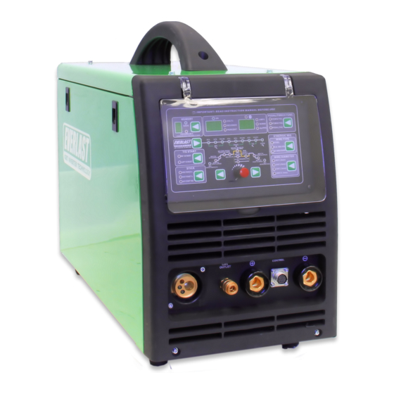
POWER MTS 251Si
A Digitally-Controlled, Multi-Process MIG/TIG/Stick Welder
CC
CV
GMAW
SMAW
GTAW
IGBT
DC
PULSE
Operator's Manual for the PowerMTS 251Si
Safety, Setup and General Use Guide
Rev. 1
0 11114-16
everlastwelders.com
Specifications and Accessories subject to change without notice.
1-877-755-9353
329 Littlefield Ave. South San Francisco, CA 94080 USA
Advertisement
Table of Contents
Troubleshooting

Related Manuals for Everlast PowerMTS 251Si


Summary of Contents for Everlast PowerMTS 251Si
- Page 1 POWER MTS 251Si A Digitally-Controlled, Multi-Process MIG/TIG/Stick Welder GMAW SMAW GTAW IGBT PULSE Operator’s Manual for the PowerMTS 251Si Safety, Setup and General Use Guide Rev. 1 0 11114-16 everlastwelders.com Specifications and Accessories subject to change without notice. 1-877-755-9353 329 Littlefield Ave. South San Francisco, CA 94080 USA...
-
Page 2: Table Of Contents
Table of Contents Section……………………………………………….Page Letter to the Customer …………………..………… Everlast Contact Information…………….…………. Safety Precautions…………………………………… Introduction and Specifications…..………………… Overview of Parameters and Specifications……. Technical Parameters……………………………... General Description, Purpose and Features……. Set Up Guide and Component Identification….…... Suggested Settings…….…………………...…….. Connections and Polarity…………………………. -
Page 3: Letter To The Customer
It is also important so that we may track your satisfaction with Everlast products and services. If you are unable to register by web- site, contact Everlast directly through the sales department at the main customer service number in your country. -
Page 4: Everlast Contact Information
Serial number: _____________________________ Model number: _____________________________ Date of Purchase:___________________________ Contact Information Everlast US: Everlast consumer satisfaction email: sales@everlastwelders.com Everlast Website: everlastwelders.com Everlast Technical Support: support@everlastwelders.com Everlast Support Forum: http://www.everlastgenerators.com/forums/index.php Main toll free number: 1-877-755 WELD (9353) 9am—5pm PST M-F 11am-4pm PST Sat. -
Page 5: Safety Precautions
Safety Precautions Everlast is dedicated to providing you with the best possible equipment and service to meet the demands of the welding applications that you have. We want to go beyond delivering a satis- factory product to you. That is the reason we offer technical support to assist you with your needs should an occasion occur. - Page 6 Safety Precautions These safety precautions are for protection of your safety and health. Failure to follow these guidelines may result in serious injury or death. Be careful to read and follow all cautions and warnings. Protect yourself and others from danger and injury. Welding and cutting processes produce high levels of ultraviolet (UV) radiation that can cause se- vere skin burn and damage.
- Page 7 Safety Precautions WARNING! Persons with pacemakers should not weld, cut or be in the welding area until they consult with their physician. Some pacemakers are sensitive to EMF radiation and could severely malfunction while welding or while being in the vicinity of someone welding. Serious injury or death may occur! Welding and plasma cutting processes generate electro-magnetic fields and radiation.
- Page 8 Safety Precautions WARNING! Electrical shock can kill. Make sure all electrical equipment is properly grounded. Do not use frayed, cut or otherwise damaged cables and leads. Do not stand, lean or rest on ground clamp. Do not stand in water or damp areas while welding or cutting. Keep work surface dry. Do not use welder or plasma cutter in the rain or in extremely humid conditions.
-
Page 9: Introduction And Specifications
Section 1 Introduction and Specifications Overview of Parameters and Features* Power i-MIG 251Si** MIG/TIG/Stick Amp Range 120V: MIG 30-150A/ TIG 10-150A/ Stick 10-120A 240V: MIG 30-250A/ TIG 10-250A/ Stick 10-200A Volt Adjustment Range MIG 120V: 15.5-22V 240V: 15.5-30V MIG Wire Feed Speed 120V: 60-400 (5-10 m/min) 240V: 60 to 600 IPM (.5-15 m/min) Input Voltage... -
Page 10: Technical Parameters
Section 1 Introduction and Specifications EVERLAST POWERMTS 251Si MODEL: PowerMTS 251Si Serial No. EN/ IEC60974.1 240V; DC: 30-250A; 15.5-26.5V 120V; DC: 30-150A; 15.5-21.5V 100% 100% 250A 200A 160A 150A 120A 26.5V 21.5V 18.5V 240V; DC: 10-250A; 10.4-20V 120V; DC: 10-150A; 10.4-16V... -
Page 11: General Description, Purpose And Features
The Stick mode also features adjustable hot start the TIG arc. The PowerMTS 251Si is the first unit in the time and hot start intensity controls which are de- industry to feature out-the-front controls for TIG, which signed to help reduce sticking during arc starts also includes a solenoid controlled gas connection. -
Page 12: Suggested Settings
The unit can handle several different while welding. Most often, the pulse MIG mode is Everlast spool gun models, but the most capable is employed as a modification of the Pulse process the 300 amp, Parker® DSP 360A spool gun. Also the user may want to consider the Everlast using a different blend of gas (≤10% CO2 typically,... - Page 13 Duty Cycle/Overcurrent/Under Voltage/Overvoltage Warnings. Thanks to a dual cooling fan design, the PowerMTS 251Si has a duty cycle rating of 40% at 250 Amps while welding in MIG and TIG mode and a rating of 40% @ 200 Amps while welding in stick mode. The...
-
Page 14: Setup Guide And Component Identification
WORK CONTROL SPOOL GUN + ** Push Pull gun and Spool gun are optional items that may be purchased separately from Everlast. STICK NOTE: In TIG mode, the user must choose between pedal opera- tion or torch switch operation. Both cannot be in use at the same time. -
Page 15: General Polarity And Amp Recommendations
Section 2 Setup Guide and Component Identification GENERAL POLARITY RECOMMENDATIONS* Table 1 *Consult the manufacturer of the filler material recommendations concerning polarity . PROCESS TORCH POLARITY WORK POLARITY MIG (GMAW) FLUX CORE (FCAW) STICK (SMAW) TIG (GTAW) GAS SELECTION GUIDE Table 2 PROCESS MIG (GMAW) STEEL... - Page 16 Section 2 Setup Guide and Component Identification TIG (GTAW) OPERATION GUIDE FOR STEEL (ALUMINUM)* *As a general rule, set amperage using 1 amp for every .001” of metal thickness for aluminum. Less is required for DC. METAL THICKNESS WELDING AMPS TUNGSTEN DIA.
-
Page 17: Installing The Wire Spool
NOTE: An adapter/spacer will be needed to use 8” spools. Contact Everlast to purchase one, if you do not have an adapter. To install the MIG gun (torch). Align pins on the torch connector with the feeder receptacle. -
Page 18: Front View Main Panel
Section 2 Setup Guide and Component Identification FRONT VIEW/ MAIN PANEL POWER i-MIG 251Si CONTROL... -
Page 19: Front Panel Item Description And Explanation
Section 2 Setup Guide and Component Identification Front Panel Description and Explanation: a defect. 1. Protective Cover. The unit features a protective 5. LED Stop Indicator. This indicator will light up hinged cover. This cover should be lowered anytime a machine fault or an electrical issue is whenever welding is actively taking place or detected. - Page 20 Section 2 Setup Guide and Component Identification you will notice while cycling between different the panel in synergic mode since wire speed/amp wire types and wire thicknesses, the basic volt control is routed through the gun, but will still be and wire feed settings do not appear to change.
- Page 21 Section 2 Setup Guide and Component Identification an HF start. This is the same type start found on enced. Consider using other welders capable of many MIG/TIG/Stick welders in it’s class. It is supporting E 6010 use if this rod is frequently more primitive, but does a good job when HF start used.
- Page 22 Section 2 Setup Guide and Component Identification Release the button and it will automatically Time and Intensity for thicker metals and thick- spring back and return to adjusting in smaller er rods. increments. 12. Sequencer. The sequencer controls the arc 15.
- Page 23 Section 2 Setup Guide and Component Identification to with other brands of machines. The arc sound gun when it is connected. will also change as the arc force is adjusted, going 19. Negative Polarity Connector (-). This front from a relatively high pitched whine to a frying mounted connector terminal is a standard 35 sizzle.
- Page 24 Section 2 Setup Guide and Component Identification amount of time it takes for the unit to decrease “0.0” without severely affecting weld quality. Amps from the maximum set amps to the mini- 3. Pre-Flow and Post-Flow of Shielding Gas. Both mum arc termination amps.
- Page 25 Section 2 Setup Guide and Component Identification the toes of the weld, or burn though may occur. In Pulse MIG mode, the MIG Volts will not be se- lectable and will default to MIG Pulse Volts when the Voltage is selected. Voltage is not adjustable in TIG or Stick mode.
-
Page 26: Side View
Section 2 Setup Guide and Component Identification SIDE VIEW POWER MTS 251Si... -
Page 27: Side View Item Description And Explanation
If you do not have an adapt- plied with additional drive roll sizes. Do not forget er, contact Everlast to purchase one. NOTE: 4” to change the contact tip size when changing to a rolls of wire are not supported. -
Page 28: Rear View Back Panel
Section 2 Setup Guide and Component Identification REAR VIEW/BACK PANEL POWERMTS 251Si FUSE 1x220V... -
Page 29: Rear Panel Item Description And Explanation
5% THD. Consult your generator manufac- turer for information regarding the clean power rating on specific units. Everlast does not pro- vide a list of approved generators. Manufactur- ers rate their units as clean power independent- ly according to industry standards. -
Page 30: Basic Theory And Function
Basic Theory and Function Section 3 BASIC MIG OPERATION General Setup of Amps and Volts. them either too hot or too cold. For some people, it When welding with the Power i-MIG, the two main may not even close. However, nothing can substi- functions that require adjustment are Voltage and tute for watching the arc and listening to the sound Wire feed speed. - Page 31 Basic Theory and Function Section 3 BASIC MIG OPERATION While Everlast uses the term “arc force”, it is known wire. While ultimately there are limits to what by many different terms. Often it is referred to as any given wire can weld on the lower end of it’s inductance, choke or slope.
- Page 32 Basic Theory and Function Section 3 BASIC MIG OPERATION released. porous weld. If the burn back control is set too long it can cause The end of the wire should be positioned just barely the wire to burn back into the tip itself and welding above the metal when the trigger is pulled for the of the wire to the tip.
- Page 33 Basic Theory and Function Section 3 BASIC MIG OPERATION for novice welders. Stringers are simply straight sufficient level of deoxidizers such as silicone and beads that move forward with little or no side to copper that are formulated to allow it to handle mi- side travel or oscillation.
- Page 34 Basic Theory and Function Section 3 BASIC MIG OPERATION Besides a butt joint and lap joint which are often used DOUBLE V-GROOVE V-GROOVE (60-80°) for thinner metal gauges, consider using one of these groove joints for best welding results. When grinding or cutting the bevels, especially with a single V- groove, it may be beneficial to leave a small land with U-GROOVE...
- Page 35 Basic Theory and Function Section 3 BASIC MIG OPERATION Problem: Gun is not being held vertical from side to side. Wire is not being directed to the center of the puddle. This concentrates heat on one side of the joint and results in poor fusion on the neglected side.
- Page 36 Section 2 Setup Guide and component Identification BASIC MIG OPERATION Characteristics: Concave weld, poor filling, possi- ble undercutting resulting in weak weld. Possible Causes: Voltage too high, not enough wire speed, too short of wire stick out, wrong gun angle. Remedy: Decrease voltage, use push motion, in- crease wire speed.
-
Page 37: Pulse Mig Operation
To understand the Everlast Pulse MIG design DC wave form. With a double-pulse type of and setup, it is important to recognize and dis-... - Page 38 Basic Theory and Function Section 3 PULSE MIG OPERATION But pulsed-spray is also used with mild or car- type of Pulse MIG commonly associated with a bon steels to allow out of position welding and “TIG” look, with well defined ripples. The to maintain production welding speed levels.
- Page 39 However, the key difference between welding in the flat position only. Everlast’s version of a single-pulse MIG and other versions of pulse MIGs is that Everlast The Everlast Pulse mode is not considered pulses voltage instead of pulsing current synergic.
- Page 40 Pulse voltage, causing an uncontrollable arc, spatter and setup time and effort will be reduced. After undercutting. The Everlast type of pulse that proceed to pulse frequency, and then, of allows you to set a higher Voltage than...
- Page 41 10-30% additional Volts (over the er arc cone. As briefly touched on earlier, standard recommended non pulse volts) as the Everlast version of MIG pulse pulses go-to starting point when setting peak Voltage, instead of current. For discussion Volts. After setting wire speed and peak purposes, the “MIG pulse Voltage”...
- Page 42 Basic Theory and Function Section 3 PULSE MIG OPERATION settings on the pulse, you will find that de- ment is also based off of pulse voltage and sirable frequencies have a fairly broad pulse time-on remaining unchanged during range. To simplify pulse frequency adjust- pulse frequency adjustment.
- Page 43 Basic Theory and Function Section 3 PULSE MIG OPERATION times referred to as pulse balance, as it set for a briefer period of time rather than indeed can be used to “balance” the time a longer period of time to prevent the wire the pulse spends in base and the peak from being fed into the puddle as it crosses stages.
- Page 44 Basic Theory and Function Section 3 PULSE MIG OPERATION puddle development and behavior. In- trimix is considerably more expensive. creasing arc force to 90% or more in stain- PULSE WORKSHEETS less applications will actually help to re- duce puddle sluggishness and increase Use the following worksheets to save and travel speed.
-
Page 45: Pulse Mig Work Sheets
Basic Theory and Function Section 3 PULSE MIG OPERATION Pulse MIG Work Sheet 1 Stainless Grade ______ Metal Thickness Wire Diameter Wire Speed/Amps Peak Voltage Base Voltage Pulse Frequency Pulse Time-On% Inductance% PGM # NOTES:... - Page 46 Basic Theory and Function Section 3 PULSE MIG OPERATION Pulse MIG Work Sheet 2 Stainless Grade ______ Metal Thickness Wire Diameter Wire Speed/Amps Peak Voltage Base Voltage% Pulse Frequency Pulse Time-On% Inductance% PGM # NOTES:...
- Page 47 Basic Theory and Function Section 3 PULSE MIG OPERATION Pulse MIG Work Sheet 3 Steel Grade ______ Metal Thickness Wire Diameter Wire Speed/Amps Peak Voltage Base Voltage% Pulse Frequency Pulse Time-On% Inductance% PGM # NOTES:...
- Page 48 Basic Theory and Function Section 3 PULSE MIG OPERATION Pulse MIG Work Sheet 4 Steel Grade ______ Metal Thickness Wire Diameter Wire Speed/Amps Peak Voltage Base Voltage% Pulse Frequency Pulse Time-On% Inductance% PGM #...
- Page 49 Basic Theory and Function Section 3 PULSE MIG OPERATION Pulse MIG Work Sheet 5 Aluminum Grade ______ Metal Thickness Wire Diameter Wire Speed/Amps Peak Voltage Base Voltage% Pulse Frequency Pulse Time-On% Inductance% PGM #...
- Page 50 Basic Theory and Function Section 3 PULSE MIG OPERATION Pulse MIG Work Sheet 6 Aluminum Grade ______ Metal Thickness Wire Diameter Wire Speed/Amps Peak Voltage Base Voltage% Pulse Frequency Pulse Time-On% Inductance% PGM #...
-
Page 51: Stick Operation
Basic Theory and Function Section 3 more CO2 is added, the rust resistance of Special Notes Concerning Operation. stainless goes down due to the added car- 1. Shielding Gas Selection for MIG and TIG. bon content. Ideally, there are several Tri- While welding aluminum with the Spool gas mixes out there that are well suited to gun or MIG gun you must use 100% Ar-... - Page 52 Basic Theory and Function Section 3 STICK OPERATION STARTING METHODS Tapping Method Scratch/Match Method Striking the Arc Make sure the unit is turned on and the startup cycle has finished. Select the Stick icon on the Process Selector. Make sure the electrode holder is in the Positive connector and the work clamp is in the negative connector. Select the Amp level desired.
- Page 53 Everlast for your unit. For the best match- control. In TIG mode you are controlling up, we recommend the Parker Pre-Flow, Post-Flow, Up and Downslope of 4.
- Page 54 Basic Theory and Function Section 3 user must choose between the two. There is no other operation style similar to a foot pedal for MIG. The “T” refers to the number of “travels” of the remote switch required to operate the programming of the sequencer.
-
Page 55: Basic Tig Operation
Basic Theory and Function Section 3 Basic TIG Operation Welding. If you are new to TIG welding, it’s General Setup. The process to set up the important that you understand that TIG weld- welder for the basic TIG mode is much less in- ing is much slower than MIG or Stick welding. - Page 56 Basic Theory and Function Section 3 Basic TIG Operation middle finger grasp the rod with the thumb forms. If you need, count as you time your propelling it forward. Other rod manipulation dips until you can do it without thinking. As variations may be used, but the key is to devel- you proceed to dip your rod into the edge of op a comfortable, natural movement that is...
-
Page 57: Tig Arc Starting
Basic Theory and Function Section 3 Note: A TIG lift start should use a nearly seamless motion. Use a light touch and a quick motion for best results. LIFT START OPERATION <1/8” Position the edge of the ceramic cup on the metal. Press and hold the torch switch or press the foot pedal. Wait for the Pre-flow to start. -
Page 58: Tungsten Preparation
Basic Theory and Function Section 3 TUNGSTEN PREPARATION 1. Use a dedicated grinding wheel or contamination may re- sult. Do not breath grinding dust! Wear eye protection and gloves. 2. Grip the Tungsten firmly. 3. Grind the Tungsten perpendic- ular to the wheel face. -
Page 59: Pulse Tig Operation
Basic Theory and Function Section 3 Pulse TIG Operation EXAMPLE 1 TIG Pulse. The TIG pulse creates two amp Peak Pulse Amps: 100 amps, values, a high and a low value that cycle back Base Amps: 50% and forth between each other while welding. Pulse Time On: 50% The upper amperage is called the “TIG Pulse AMPS... - Page 60 Basic Theory and Function Section 3 Pulse TIG Operation is the percentage (%) of time that the pulse stays in the TIG (Peak) pulse Amp stage of the cycle. Increasing the Pulse time-on will increase the duration the Peak Amp stage of the cycle which in turn will increase the heat and will increase penetration.
-
Page 61: Tig Work Sheets
Basic Theory and Function Section 3 TIG OPERATION TIG Work Sheet 1 Steel Grade_______ Metal Tungsten Filler Gas Flow Welding Peak Amps Base Amps % Pulse Frequency Pulse Time-On% PGM # Thickness Size/Type Diameter Rate/Type Amps (If Applicable) (If Applicable) (If Applicable) (If Applicable) NOTES:... -
Page 62: Tig Operation
Basic Theory and Function Section 3 TIG OPERATION TIG Work Sheet 2 Stainless Steel Grade_______ Metal Tungsten Filler Gas Flow Welding Peak Amps Base Amps % Pulse Frequency Pulse Time-On% PGM # Thickness Size/Type Diameter Rate/Type Amps (If Applicable) (If Applicable) (If Applicable) (If Applicable) NOTES:... - Page 63 Basic Theory and Function Section 3 TIG OPERATION TIG Work Sheet 2 Aluminum Grade_______ Metal Tungsten Filler Gas Flow Welding Pulse Pulse Pulse Pulse PGM # Thickness Size/Type Diameter Rate/Type Amps Freq. Balance Peak Amps Base Amps % Frequency Hz Time-On% (If Applicable) (If Applicable)
-
Page 64: 25 Series Mig Torch
Basic Theory and Function Section 3 25 SERIES MIG TORCH Expanded View NOTE: Over time, pressure on the drive rolls causes metal fragments from the filler wire’s surface to find its way to the gun cable liner. If the wire guide is not cleaned, it can gradually clog up and causes wire feed malfunctions. If feeding difficulty is observed, clean the liner in the following manner:... -
Page 65: Series Consumables
Basic Theory and Function Section 3 TORCH CONSUMABLE LIST FOR 25 SERIES MIG TORCH Item # Part # I Ref # T Ref# B Description Size Image MC0022 145.0124 Nozzle 11.5x57mm ICS0078 MC0023 145.076 Nozzle Std. 15x57mm MC0024 145.00042 Nozzle 18x63.5mm MC0025 145.0169... -
Page 66: 24 Series Mig Torch
Binzel®, Trafimet®, or other similar manufacturer. The Innotec® listed above is currently the default supplier of the 36 series. Everlast is not the torch manufacturer, but equips the PowerMTS units with some of the most proven torches in history. Numer- ous manufacturers all over the world use variations of these torches. -
Page 67: Series Consumables
Euro connector as an option. This list is provided as a general cross reference and does not guar- antee that every variation or type is directly available from Everlast. In the left column, are the OEM part numbers. Trafimet ® and Binzel®... -
Page 68: Series Tig Torch
Basic Theory and Function Section 3 EXPANDED VIEW OF TIG TORCH 5/8” PARTS FOR 17/26 Series Torch ( STYLE MAY VARY) Long Back Cap with O-Ring Short Back Cap Opt. Torch Head Insulator Collet 1/16 or 3/32 Collet Holder Ceramic Cup #5,6, or 7 Tungsten (customer supplied) Torch Cable Torch Handle... -
Page 69: Troubleshooting Guide
Wire continues feeding but no large diameter wires. Check power plug for problems. arc is present. If easily tripped the Resistor value too low. (Contact Everlast if OC is tripping regularly with normal settings.) Potentiometer damaged. Repair or Replace it. Welding Voltage/Current is uncon- trollable Control board damaged. -
Page 70: Troubleshooting Guide
Solenoid is for higher flow of gas. Listen for audible click of gas sticking. Too short of pre-flow or solenoid. If no click is heard, then contact Everlast post-flow Support. Clean weld properly. Increase pre flow or post flow. -
Page 71: Error Codes
Troubleshooting Guide Section 4 Error Codes Error Code Meaning Possible Cause Over Voltage/Under Voltage Check Power Source, Correct Wiring. Over Current Operating machine on too small of a conductor. Internal machine fault Over Temperature Duty Cycle exceeded. Blocked cooling. Fans not operating properly. Stuck Switch Gun switch is held too long without at- tempting to strike an arc.
Need help?
Do you have a question about the PowerMTS 251Si and is the answer not in the manual?
Questions and answers