Table of Contents
Advertisement
CC
GTAW-P
SMAW
IGBT
1
~
PHASE
DC
120/240
DV
Operator's Manual for the Power i-Tig 200T
everlastwelders.com
EVERLAST
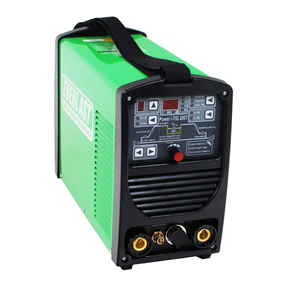
POWER i-TIG 200T
DIGITAL DC PULSE TIG/STICK WELDER
Safety, Setup and General Use Guide
380 Swift Ave. Unit 12 South San Francisco, CA 94080
1-877-755-9353
Rev. 2
Specifications and Accessories subject to change without notice.
0 00409-19
Advertisement
Table of Contents

Related Manuals for Everlast POWER i-TIG 200T


Summary of Contents for Everlast POWER i-TIG 200T
- Page 1 POWER i-TIG 200T DIGITAL DC PULSE TIG/STICK WELDER GTAW-P SMAW IGBT PHASE 120/240 Operator’s Manual for the Power i-Tig 200T Safety, Setup and General Use Guide Rev. 2 0 00409-19 everlastwelders.com Specifications and Accessories subject to change without notice. 1-877-755-9353...
-
Page 2: Table Of Contents
The owner of this product assumes all liability for its use and maintenance. Everlast Power Equipment INC. does not warrant this product or this document for fitness for any particular purpose, for performance/accuracy or for suitability of application. -
Page 3: Letter To The Customer
Your unit registration is important should any information such as product updates or re- calls be issued. It is also important so that we may track your satisfaction with Everlast products and services. If you are unable to register by website, contact Everlast directly through the sales department through the main customer service number in your country. -
Page 4: Everlast Contact Information
Model number: ____________________________ Date of Purchase___________________________ EVERLAST Contact Information Everlast US: Everlast consumer satisfaction email: sales@everlastwelders.com Everlast Website: everlastwelders.com Everlast Technical Support: support@everlastwelders.com Everlast Support Forum: http://www.everlastgenerators.com/forums/index.php Main toll free number: 1-877-755 WELD (9353) 9am—5pm PST M-F 11am-4pm PST Sat. -
Page 5: Safety Precautions
Safe operation and proper maintenance is your responsibility. We have compiled this operator’s manual, to instruct you in basic safety, oper- ation and maintenance of your Everlast product to give you the best possible experience. Much of welding and cutting is based upon experience and com- mon sense. - Page 6 SAFETY PRECAUTIONS These safety precautions are for protection of safety and health. Failure to follow these guidelines may result in serious injury or death. Be careful to read and follow all cautions and warnings. Protect yourself and others. Welding and cutting processes produce high levels of ultraviolet (UV) radiation that can cause severe skin burn and damage.
- Page 7 SAFETY PRECAUTIONS WARNING! Persons with pacemakers should not weld, cut or be in the welding area until they consult with their physician. Some pacemakers are sensitive to EMF radiation and could severely malfunction while welding or while being in the vicinity of someone welding.
- Page 8 SAFETY PRECAUTIONS continued WARNING! Electrical shock can kill. Make sure all electrical equipment is properly grounded. Do not use frayed, cut or otherwise damaged cables and leads. Do not stand, lean or rest on ground clamp. Do not stand in water or damp areas while weld- ing or cutting.
-
Page 9: Introduction And Specifications
Section 1 Introduction and Specifications Power i-TIG 200T Air-Cooled, 26 Series Torch Assembly 12.5 ft (Style may Vary) Argon Regulator Work Clamp Consumable Kit (Does not include Tungsten) 47K Ω Stick Electrode Holder Foot Pedal Assembly optional NOTE: Accessory and consumable style and quantities are subject to change without notice. -
Page 10: Unit Specifications
Section 1 Introduction and Specifications Power i-TIG 200T Digital TIG/Stick Welder Specification Process DC GTAW-P/DC SMAW Inverter Type Digital microprocessor controlled with Infineon IGBT con- struction (non module design) Minimum/Maximum Rated Output TIG DC: 3 A/10.1 V - 200 A/18V Minimum/Maximum Rated Output Stick 5 A/20.2 V - 160 A/26.4 V... -
Page 11: General Overview
A. Infineon microprocessor and IGBT components pro- vide excellent reliability while retaining an inexpen- Duty Cycle. For the Power i-Tig 200T, the duty cycle is sive design. The modular plug and play design re- rated for 35% at 200 amps for TIG and 35% at 160 amps duces maintenance and improves serviceability. - Page 12 DINSE connector is the return line from the torch to the cooler (cooler is marked “input”) with the red coupling. In some Everlast versions of the torch this return is actually a blue line. In any case, the return line should be the line that exits directly from the DINSE Connector.
-
Page 13: Quick Setup Guide, Stick Polarity
Section 2 QUICK SETUP AND USE GUIDE QUICK SETUP GUIDE: STICK POLARITY AND CONNECTIONS TORCH WORK PIECE CONTROL TORCH (+) WORK (-) -
Page 14: Rear Panel Gas Connection And Wiring
5/8 CGA Fitting (Newer) 2014 USA /CA models use 5/8” CGA gas (Ar) fitting on rear NOTE: SOME MODELS ARE CALIBRATED IN LITERS/MINUTE (lpm) EVERLAST NOTE: Use Ar or Ar/He only. Do not use more than 25% He in the Ar/He gas mix. -
Page 15: Front Panel Features And Controls
Section 2 QUICK SETUP AND USE GUIDE FRONT PANEL FEATURES AND CONTROLS 13. PARAMETER/AMP/ FUNCTION DISPLAY 12. PROCESS SELECTOR 1. MEMORY 11. 2T/4T SWITCH 2. ARC START SELECTOR 10. TIG FUNCTIONS A) PRE/POST FLOW B) START/END AMPS C) UP/DOWN SLOPE D) PEAK AMPS 3. - Page 16 Section 2 QUICK SETUP AND USE GUIDE FRONT PANEL FEATURES AND CONTROLS CONTINUED FEATURES PARAMETERS PURPOSE 1. Memory The memory function will save favorite or frequently used settings. To save the settings, simply select the desired operating parameters, then press and hold the selector button next to the memory display for three seconds to save the setting.
- Page 17 Section 2 QUICK SETUP AND USE GUIDE FRONT PANEL FEATURES AND CONTROLS CONTINUED FEATURE PARAMETERS PURPOSE 10. TIG functions (continued) .1-500Hz Pulse Frequency (Pulses per second). Represented by Hertz (Hz), the pulse frequency adjusts the actual number of times persecond the pulse makes one complete cycle between welding amps (Peak value) and pulse amps (Background (low) amp value).
-
Page 18: Rear Panel Features And Controls
Section 2 QUICK SETUP AND USE GUIDE REAR PANEL FEATURES AND CONTROLS 1. 1 OR 2-POLE POWER SWITCH 1~220 V 4. HF GROUND BOLT 2. POWER CABLE 1 ~ 120/240V INLET 3. GAS INLET... - Page 19 Contact the manufacturer of the generator for this information. Everlast does not have an “approved” list of generators. But, if the generator is not listed as clean power by its manufacturer, then operation is prohibited. Generators that do not at least meet the operating input requirements of the welder are also forbidden to be used with the welders.
-
Page 20: Welder Function Summary And Explanations
POST FLOW mental conditions. = UP ON SWITCH 2. Cooling. When using the Power i-TIG 200T, particu- = DOWN ON SWITCH larly during long periods of welding, even when not at maximum amps, leave the welder switched on to al- low the unit to keep cooling. - Page 21 The upper amperage is PulseAmps: 50% called the “welding amps” ( called “Peak” Amps on Pulse Time On: 50% the Power i-TIG 200T) and the lower amperage is DC Pulse Frequency: 1 Hz AMPS called “pulse amps “ (sometimes called “background”...
- Page 22 Amp % on the panel. Welding Everlast. Do not use a nipple that is scarred, bent or other- with pulse and the foot pedal takes practice, as it will wise deformed.
-
Page 23: Tungsten Preparation
Section 3 Basic theory and function TUNGSTEN PREPARATION 1. Use a dedicated grinding wheel or contamination may re- sult. Do not breath grinding dust! Wear eye protection and gloves. 2. Hold Tungsten firmly. 3. Grind perpendicular to grind- ing wheel face. Allow tungsten to grind away slowly, creating point. -
Page 24: Lift Start And High Frequency Start
Section 3 Basic theory and function LIFT START TIG OPERATION Note: A Lift TIG start should be done with a nearly seamless motion. Use a light touch and a quick motion for best results. <1/8” 1. Position the edge of the ceramic cup on the metal. Press and hold the torch switch or press the foot pedal. Wait for the Pre-flow to start. -
Page 25: Stick Starting Methods
Section 3 Basic theory and function STICK OPERATION STARTING METHODS Scratch/Match Method Tapping Method 1. Turn on the power switch on the rear of the unit. Allow unit to cycle through its start up program. 2. Select the Stick mode with the HF/Lift Start/Stick selector switch. 3. -
Page 26: Recommendations For Polarity/Amps/Tungsten
Section 3 Basic theory and function GENERAL POLARITY RECOMMENDATIONS* *Follow manufacturer of stick electrode for complete polarity recommendations PROCESS TORCH POLARITY WORK POLARITY TIG (GTAW) STICK (SMAW) TIG (GTAW) OPERATION GUIDE FOR STEEL METAL THICKNESS WELDING AMPS TUNGSTEN DIA. Ar FLOW RATE 1-3 mm/.040”-1/8”... -
Page 27: Expanded View Of Tig Torch
Section 3 Basic theory and function EXPANDED VIEW OF TIG TORCH (Actual appearance may vary slightly from what is listed.) 5/8” PARTS FOR 26 Series Torch ( STYLE MAY VARY) QTY. Long Back Cap with O-Ring Short Back Cap Opt. Torch Head Insulator Collet 1/16 or 3/32... -
Page 28: Pin Connector Pin-Out
Section 3 Basic theory and function 7 PIN CONNECTOR FOR 47K Ω FOOT PEDAL Bridge to 7 To Pedal or Torch Switch Bridge to 6 To Pedal or Torch Switch... -
Page 29: Troubleshooting
Check gas flow. Adjust for higher flow of gas. Listen for audible click of gas solenoid. If no click is heard, then contact Everlast Support. Clean weld proper- ly. Too short of post flow. Check tungsten stick out.
Need help?
Do you have a question about the POWER i-TIG 200T and is the answer not in the manual?
Questions and answers