Table of Contents
Advertisement
®
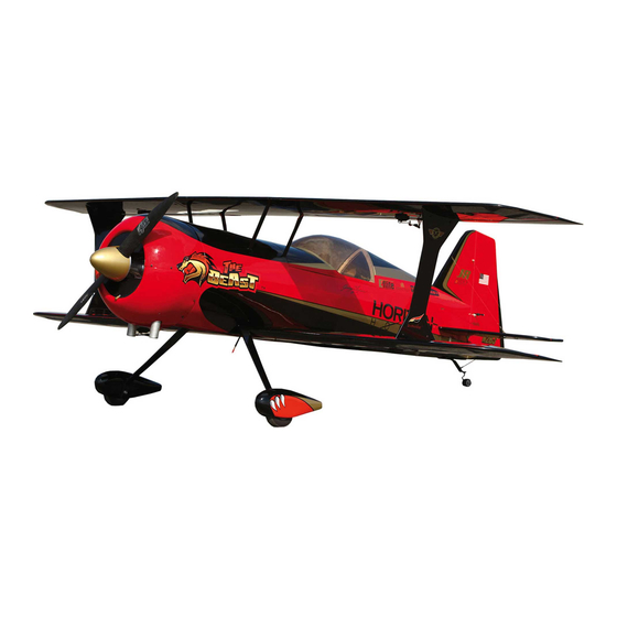
Beast
100
Assembly mAnuAl
Specifications
Wingspan.................................89.0 in (2,260mm)
Overall Length ........ 87 in (2210mm) with spinner
Wing Area .......................2,490 sq in (161 sq dm)
Flying Weight ........................26–28 lb (12–13 kg)
Engine Size ............................................ DA 100L
Advertisement
Table of Contents

Related Manuals for Hangar 9 Beast 100


Summary of Contents for Hangar 9 Beast 100
- Page 1 ® Beast Assembly mAnuAl Specifications Wingspan.........89.0 in (2,260mm) Overall Length ..87 in (2210mm) with spinner Wing Area .......2,490 sq in (161 sq dm) Flying Weight ......26–28 lb (12–13 kg) Engine Size ..........DA 100L...
-
Page 2: Table Of Contents
Recommended Engine Setup ........5 Beast 100 Introduction and Optional Sun Cover ......6 A Word From The Creator Of The Beast . - Page 3 Warranty Period ..........63 Limited Warranty .
-
Page 4: Required Tools And Adhesives
• True Red (HANU866) Before Starting Assembly Before beginning the assembly of the Beast 100, remove each part from its bag for inspection. Closely inspect the fuselage, wing panels, rudder, and stabilizer for damage. If you find any damaged or missing parts, contact the place of purchase. Go over the covering using a heat gun or sealing iron. -
Page 5: Radio And Power Systems Requirements
Radio and Power Systems Requirements • 7-channel computer radio system (minimum) with receiver • Large Servo Arms (JRPA236) (6 pkgs) • 3-Inch Double-Sided JR Arm (JRPA237) (1) • 24-Inch Servo Lead Extension (JRPA102) (5) • JR Charge Jack Switch (JRPA004) (1) •... -
Page 6: Beast 100 Introduction And Optional Sun Cover
Darker colors absorb heat more than lighter colors. We strongly recommend the use of a sun cover to protect the airplane at the field. Hangar 9 offers a white plane sun cover (HAN9170) that you can purchase as an optional accessory and easily put on... -
Page 7: A Word From The Creator Of The Beast
The Beast, in both full size and RC versions, is the product of shared information between RC and Full Scale designers. The Hangar 9 Beast is a fantastic model airplane with outstanding performance, great looks, and solid construction. Enjoy your Beast and let it “Roar to Life” at a... -
Page 8: Rudder Installation
Rudder Hinging Required Parts • Rudder • Vertical fin • Hinge rod Required Tools and Adhesives • Drill • Petroleum jelly Step 1 Pass the rod with some low viscosity lubricant through the rudder and vertical fin separately. This will lubricate the hinges on each side ... -
Page 9: Rudder Vertical Fin And Control Horn Installation
Rudder Vertical Fin and Control Horn Installation Required Parts • Rudder • Vertical fin • Hinge rod • Rudder control horn hardware Required Tools and Adhesives • Hobby knife, #11 blade • Ruler • Thin CA • Threadlock • 30-minute epoxy •... - Page 11 Step 3 Install the rudder control horn by passing the bolt through the rudder. Use a drill on a slow speed for ease of installation. It would be best to have the bolt centered on the rudder.
- Page 12 Step 4 Put the nut on with threadlock and tighten them on both sides. Install the control horn so the distance between the hinge line and pivot point of the horn measures 1 1/4 inch. Test this by installing the arm, if one control horn is off, you won't have a straight shot at 1 1/4 inch hole of the arm.
- Page 13 Step 5 Go over the covering on the fuselage opening with a heating iron. Glue the vertical fin to the fuselage using either 30-minute epoxy or wood glue. Wipe out the excess with alcohol swabs. In case of using wood glue make sure to allow 24 hours for wood glue to cure.
-
Page 14: Landing Gear And Wheel Pants Assembly
Landing Gear and Wheel Pants Assembly Required Parts • Fuselage assembly • Main landing gear • #8 washer (4) • 8-32 locknut (4) • Axle w/nut (2) • #4 washer (4) • 4-40 blind nut (4) • 4 -inch (114mm) wheel (2) •... - Page 15 Step 3 Install the other wheel collar, as in previous step. Leave a small gap between the wheel and collar to avoid braking. The wheel should turn freely. Tighten the nut on the axle using a #12 and a crescent wrench. ...
-
Page 16: Horizontal Stab Installation
Horizontal Stab Installation Required Parts • Stab assembly Required Tools and Adhesives • Thin and medium CA • Acetone • Hobby knife • 32 - 36-inch Ruler • Marker Step 5 Note: Make sure the horizontal The landing gear is fully assembled stab is completely centered and and ready to install in the fuselage. - Page 17 The measurement should read approximately 16 13/16 inch from the fuselage to the tip of the stab as shown in the first picture of Step 1 and 29 1/2 inch from the turtle deck to the tip of the trailing edge of the stab as shown above.
- Page 18 Step 3 Reinsert the stab. Make measurements and make sure it is where it should be. With the plane sitting upright and without moving it, use super thin (thin) CA to glue the stab to the fuselage. Do not move anything, thin CA will be absorbed.
- Page 19 Step 4 To ensure your stab is properly glued, apply extra CA (medium) by extending your hand inside the fuselage and applying some CA over the horizontal bracing and stab.
-
Page 20: Elevator Hinging
Elevator Hinging Required Parts Step 2 • Left elevator Using 30-minute epoxy, glue all the way in and around the pocket walls of the pockets in Required Tools and Adhesives the stab. Then apply some to the hinge itself. •... - Page 21 Step 3 Mate the elevator and stab. Make sure there is not too much of a gap between the two. Use the other side of the elevator gap as reference. Move the elevator through its full up and down deflection to ensure there is no binding.
-
Page 22: Cabane And Mid Wing Section Installation
Cabane and Mid-Wing Section Installation Required Parts • Mid-wing section • (8) 10mm, 4-40 screws • (4) 6-32 screws Required Tools and Adhesives • 3/32 in and 7/64 in ball drivers • Threadlock Step 1 Insert the cabanes in the hatch slots such that the tabs face away from fuselage. -
Page 24: Stab Flying Wire Installation
Stab Flying Wire Installation Required Parts • Flying wire hardware package provided with the kit • Tail gear Required Tools and Adhesives • Crimper • 1/4-inch wrench • 3/32-inch ball driver • Threadlock Step 1 The brass plates included in the hardware will be used for this step. - Page 25 Step 3 Pass the wire through the crimp, through the plate and back through the crimp to loop it. Crimp the non-adjustable side. Repeat the same steps for the adjustable side but pull on it so there is no slack and then crimp. Adjust once all crimping is finished.
-
Page 26: Tail Gear Steering Installation
Tail Gear Steering Installation Required Parts Using a pin wise and 1/16-inch bit, make two pilot holes. Screw the T-plate to the bottom • Tail gear assembly rudder using servo screws, then take them Required Tools and Adhesives out, apply thin CA to the holes and attach the •... - Page 27 Step 4 Make sure the rudder is centered and cut the rod to the appropriate length and Z-Bend the top of the rod to be inserted to the plate. Now proceed with final installation on the tiller arm. Apply threadlock to the nut, make any necessary adjustment to the length and tighten the nut.
-
Page 28: Rudder Servo And Pull-Pull Installation
Rudder Servo and Pull-Pull Installation Required Parts • Servo JR 8711 or JR 8911HV (1) • 3-inch Servo arm • Hangar 9 hardware pack Required Tools and Adhesives • Crimper • 1/4-inch wrench • 3/32-inch ball driver • Threadlock The rudder servo needs to be digital and requires 400 oz-in of torque. - Page 29 Step 2 Pull the cables in the rudder side before crimping. Adjust the tension by opening the Phillips head screw in the horn, tighten as necessary, then use threadlock and reassemble the horn. Note that control horn assembly of the rudder was done in the rudder hinging section.
-
Page 30: Cowl Installation
Cowl Installation Required Parts • Aluminum L-brackets and wooden tabs • 4-40 screws 1/2-inch and 1/4-inch (6 and 12 mm) • #4 washers Required Tools and Adhesives • 3/32-inch ball driver • Threadlock Step 1 Loosely attach the L-brackets, using 1/4-inch 4-40 and #4 washers, to the bottom half of the fuselage. - Page 31 Step 3 Attach the top half cowl to check the connections. Use 1/4-inch 4-40 screws and #4 washers for mid section attachments.
-
Page 32: Da 100L Engine And Throttle Installation
DA 100L Engine and Throttle Installation Required Parts • Desert Aircraft 100L • DA stock mufflers • MTW TD 75 and 50mm drop flex header • Du-Bro 4-40 E/Z connectors (2) (DUB490) • JR 8717 or JR 4721 throttle servo •... - Page 34 Step 2 Step 3 Canister mounts come preglued but silicone Prepare the canisters and headers to slide in supports are not in place. Cut (8) 9/16-inch the tunnel as follows. 1. Install the Teflon ® coupler on the header. pieces of silicone tube and mount them through the slots in the mounts.
- Page 35 Disclaimer: Teflon ® is a trademark or registered trademark of E.I. DuPont de Nemours and Co. Corporation, Wilmington, Delaware.
- Page 36 Cowl Cutting Use the template provided at the end of the manual to cut the cowl for DA100L stock muffler installation. Attach the template to the bottom cowl through the two bottom bracket screw holes. The template should lay tight on the bottom cowl.
-
Page 37: Fuel Tank Installation
Fuel Tank Installation Required Parts Step 2 • Fuel tank Reassemble the tank. Make sure the cap is • Du-Bro 1/4-inch foam (DUB513) secure but avoid over-tightening. • Aluminum T-fuel filter (JRP960298) Cut some 1/4-inch foam the size of the bottom of the tank. - Page 38 Step 3 Step 4 Use sticky back Velcro ® to the foam. Then Use the aluminum T-fueler for the carb CA the opposite side of the Velcro to the tank connection. Tie wrap the connections to avoid tray in the fuselage. This prevents the tank any air leaks.
-
Page 39: Wing Servo And Control Horn Installation
Wing Servo and Control Horn Installation Required Parts • Hangar 9 ball links, titanium rods and bolts • (4) JR 8711 or similar power digital servo • (4) JR 1.5-inch single sided arm • (2) 6- and 12-inch JR-HD extensions Required Tools and Adhesives •... - Page 40 Step 3 Install the servo in the wing so the output shaft is toward the leading edge of the wing. Use 1/16-inch drill bit to drill pilot holes for servo screws, then go over the holes with thin CA. Wait until it cures before inserting the servo in the bay and securing it.
- Page 41 Step 4 The distance from the hinge line to the top of the bolt at the pivot point should measure 40mm. The length of titanium rod exposed should measure 22mm. These measurements should be the same for all 4 wings. Attach the 1.5-inch arm to the ball link and complete the assembly.
- Page 42 Step 6 To pass the bottom wing extension inside the fuselage follow the directions below. 1. Make a size cut bigger than the plug in the fuselage where the wing root is going in and where it would line up with the extension exit from the wing root.
- Page 43 Note: The step below may not be necessary with production models. Please ignore if your model has the anti-rotation pin sleeve preglued. Step 7 You will need to glue in the anti-rotation pin sleeve for the bottom wing by following the steps below.
-
Page 45: Elevator Servo And Control Horn Installation
Required Parts Insert the bolt through the elevator; do not tighten the nut but turn the nut up the bolt. • Hangar 9 ball links, titanium rods and Hold the control horn at the tip of the bolt bolts and turn the bolt to grip the horn and stop •... - Page 46 The picture above is how you need to measure 1.5- inch from the hinge line. Step 3 Install the servo so the output shaft is toward the tail of the aircraft. Pass the extensions through the bottom former's lightening holes, secure the connector using dental floss and the masking method described in the wing section.
-
Page 47: Battery Installation
Step 1 Prepare the tray completely before gluing it in place. Wrap masking tape to the bottom of each battery. Then CA Velcro to the masking tape on the batteries and also the tray. (i.e., soft part of Velcro to the batteries and mating part to the tray). - Page 48 Step 2 The tray is now ready to be secured to the fuselage frame. Scratch up the surface that will sit on the fuselage rail with a hobby knife. Mix some 30-minute epoxy and brush it up on the tray. Apply a small amount to the fuselage frame and place the tray in the fuselage.
-
Page 49: Regulators And Receiver Installation
Regulators and Receiver Installation Required Parts • (2) Spekrum 10-Amp Regulators (SPMVR6010) • AR9100 PowerSafe (SPMAR9100) • (2) 24- and 36-inch JR HD Extension Required Tools and Adhesives • 1/8-inch lightweight plywood • Medium and thin CA • Servo screws •... - Page 50 Step 3 Step 4 Switch number two follows the same step Follow the steps below to prepare the as switch number one. Before installing the receiver for mounting. screws, use a 1/16-inch drill bit and slowly 1. Apply masking tape to the bottom of the drill pilot holes in the sheeting, then add a tiny receiver.
- Page 51 4. Glue using CA opposite side of Velcro on Note: It is still necessary to perform the rudder tray to complete the installation. a healthy range check and make any adjustment needed to the location of satellite receivers for best results. A Spektrum Flight Log (SPM9540) can be very helpful for this process.
- Page 52 Top wing extensions can be secured to the struts using black electrical tape or by cutting strips of black UltraCote, making a loop and ironing them to the struts. Step 6 Run (2) 24-inch extensions from the receiver for the bottom wings and (2) 36-inch extensions for the top wings.
-
Page 53: Ignition And Switch Installation
Ignition and Switch Installation Required Parts • Deluxe switch harness (JRPA001) • (1) Spekrum 2S, 1350mAh Li-Po with Spektrum regulator (VR5203) • Ignition module • Flex Guard 1/4-inch split convoluted tubing for spark plug wire protection • Sticky back Velcro •... - Page 54 Step 4 Mount the appropriate battery for your ignition module next to the ignition in an available slot. It is best to mount the battery closer to where the switch is mounted. Step 3 Use hot glue to secure the ignition switch wires to the side of the engine box.
-
Page 55: Applying Decals
Applying Decals All large decals should be applied wet so the bubbles can be worked out by squeegee. Allow 24 hours for decals to dry and adhesive to set. It is important to take all the wrinkles in the covering out and would be best to apply the decals after the plane has been taken to a flying field a couple of times and all the wrinkles have been removed. -
Page 56: Balancing The Model
Balancing the Model This is a very important step that should not be skipped before your first flight. Balancing the model correctly not only improves the flying performance but also reduces the amount of coupling. The best Center of Gravity is at 63mm from the leading edge of bottom wing toward the trailing edge of the wing. -
Page 57: Control Throws
Control Throws Use a throw meter such as Hangar 9 digital meter or similar. For the rudder, you do not need to use the throw meter. Adjust for maximum possible throw and half that for flight mode 2 explained below. Throws are equal for up and down elevator and left and right aileron. This aircraft does not need differential on ailerons. -
Page 58: Rudder To Elevator And Aileron Mixes
Rudder to Elevator and Aileron Mixes Quique Somenzini has designed the Beast to have minimum roll and pitch coupling, but at the same time pitch and roll coupling of any plane is extremely dependent on its CG. Quique uses multi-point (curve) mixes for Rudder to Elevator and Rudder to Aileron. The numbers below are from his own transmitter. -
Page 59: 12X Crow Feature
12X Crow Feature Follow the table below for appropriate aileron connections. Right Top Wing Right Bottom Wing Gear Left Top Wing Aux3 Left Bottom Wing Aux2 Define the mix below and assign it to a switch. The example switch below is Rudder D/R and crow is mixed with throttle. -
Page 60: Extreme 3D Setup
SuperSteel ™ gears to take the extra abuse. 2. Get 50 to 55 degrees of elevator deflection by replacing the 2.5-inch titanium pro-link included in the kit with the 3-inch Hangar 9 pro-link (HAN3553). The extra 10 degrees in deflection would allow even tighter pitch maneuvering. -
Page 61: Final Pictures Of Plane Assembly And Setup
Final Pictures of Plane Assembly and Setup Left and right interplane struts in order from Bottom wing attaching to fuselage left to right Bottom wing extension in the fuse Top wing attachment Left interplane strut assembled Top wing 6-32 screw joint... - Page 62 Top wings extension routing Regulators location Bottom wing attachment MatchBox setup, one on each side of receiver 12X setup, no MatchBox Engine and ignition setup...
-
Page 63: Warranty Period
Warranty Period Exclusive Warranty- Horizon Hobby, Inc., (Horizon) warranties that the Products purchased (the "Product") will be free from defects in materials and workmanship at the date of purchase by the Purchaser. Limited Warranty Horizon reserves the right to change or modify this warranty without notice and disclaims all other warranties, express or implied. -
Page 64: Safety Precautions
Safety Precautions This is a sophisticated hobby Product and not a toy. It must be operated with caution and common sense and requires some basic mechanical ability. Failure to operate this Product in a safe and responsible manner could result in injury or damage to the Product or other property. This Product is not intended for use by children without direct adult supervision. -
Page 65: Non-Warranty Repairs
Non-Warranty Repairs Should your repair not be covered by warranty the repair will be completed and payment will be required without notification or estimate of the expense unless the expense exceeds 50% of the retail purchase cost. By submitting the item for repair you are agreeing to payment of the repair without notification. -
Page 66: Safety, Precautions, And Warnings
Germany Electronics and engines requiring inspection or repair should be shipped to the following address: Horizon Technischer Service Hamburger Strasse 10 25335 Elmshorn Germany Please call +49 4121 46199 66 or e-mail us at service@horizonhobby.de with any questions or concerns regarding this product or warranty. France Electronics and engines requiring inspection or repair should be shipped to the following address:... -
Page 67: Instructions For Disposal Of Weee By Users In The European Union
Instructions for Disposal of WEEE by Users in the European Union This product must not be disposed of will help to conserve natural resources and with other waste. Instead, it is the user’s ensure that it is recycled in a manner that responsibility to dispose of their waste protects human health and the environment. -
Page 68: 2010 Official Ama National Model Aircraft Safety Code
2010 Official AMA National Model Aircraft Safety Code GENERAL 8. I will not operate model aircraft carrying pyrotechnic devices which explode burn, or propel a projectile 1. A model aircraft shall be defined as a non-human- of any kind. Exceptions include Free Flight fuses carrying device capable of sustained flight in or devices that burn producing smoke and are the atmosphere. -
Page 69: Radio Control
2010 Official AMA National Model Aircraft Safety Code Radio Control 7. With the exception of events flown under official AMA rules, no powered model may be flown 1. All model flying shall be conducted in a manner to outdoors closer than 25 feet to any individual, avoid over flight of unprotected people. - Page 70 © 2010 Horizon Hobby, Inc. horizonhobby.com 16725 Created 01/10...
Need help?
Do you have a question about the Beast 100 and is the answer not in the manual?
Questions and answers