Flashforge Creator Pro User Manual
Hide thumbs
Also See for Creator Pro:
- User manual (55 pages) ,
- Quick start manual (40 pages) ,
- Start up and instruction manual (27 pages)

Subscribe to Our Youtube Channel
Related Manuals for Flashforge Creator Pro


Summary of Contents for Flashforge Creator Pro
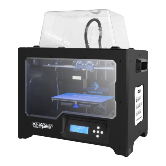
- Page 1 User Guide Flashforge Creator Pro 3D Printer User Guide Creator Pro Desktop 3D Printer...
-
Page 2: Table Of Contents
Contents Contents........................2 Preface........................3 Introduction........................ 4 Notice......................... 4 Safety Notice......................5 Chapter 1: 3D Printing Technology................8 Chapter 2: Accessories....................10 Chapter 3: Unpacking....................11 Chapter 4: Hardware Assembly.................14 Chapter 5: About Software..................16 5.1 Software Installation................16 5.2 Exploring FlashPrint................16 Chapter 6: Basic Printing..................33 6.1 Generate a Gcode.................. -
Page 3: Preface
Preface On the completion of this User Guide, I here, on behalf the Flashforge team, would like to avail myself of this opportunity to express my great gratitude to the all Flashforge engineers and the Flashforge 3D printer users for their unremitting efforts and sincere assistance. -
Page 4: Introduction
·The version of the Firmware is 20160122. ·The device illustrations in the User Guide hall be those of Creator Pro. The Flashforge Creator Pro 3D Printer User Guide contains the information needed for you to set up and use this device. -
Page 5: Safety Notice
① Always use the Creator Pro with a properly grounded outlet. Do not modify Creator Pro plug. ② Do not use Creator Pro in damp or wet locations. Do not expose Creator Pro to burning sun. ③ Do not abuse the cord. - Page 6 Temperature: RT 15-30℃ Moisture: 20%-50% · Filament Requirements Do not abuse the filament. Please make sure you use the Flashforge filament or the filament from the brands accepted by Flashforge. Legal Notice All the information in this document is subject to any amendment or change without the official authorization from Flashforge.
- Page 7 OF MERCHANTA- BILITY AND FITNESS FOR A PARTICULAR PURPOSE. Flashforge shall not be liable for errors contained herein for incidental consequential damages in connection with furnishing, performance or use of this material This document contains proprietary information protected by copyright.
-
Page 8: Chapter 1: 3D Printing Technology
Fused Filament Fabrication(FFF) is the most common method of 3D printing. It is also the method that the Creator Pro uses. It works by melting plastic material called filament onto a print surface in high temperature. The filament solidifies after it cools down, which happens instantaneously after it is extruded from the nozzle. - Page 9 Using FlashPrint, you can prepare stl. files to be x3g files for printing. Then users can print files via SD card. ③ Build the 3D Model: Once the output file has been transferred to your Creator Pro, it will start to turn the 3D model into a physical object by laying down layers of filament.
-
Page 10: Chapter 2: Accessories
Chapter 2: Accessories Along with your Creator Pro 3D printer, the box also contains the followings: On the top of the PE foam sheet, you’ll find: Filament guide tube*2 Quick start*1 Build tape*2 Leveling card*1 Within the accessory PE foam ... -
Page 11: Chapter 3: Unpacking
Flashforge leveling card and one Quick Start Guide. Firmly grasp the two side handles of Flashforge Creator Pro. Lift it out of the box and place it on a stable surface. Then open and remove the transparent covering. -
Page 12: Power
a power cable, a USB cable, two Take the accessory foam container out, within which are lying spool holders, a bag of tools, a SD card, a bag of extruder accessories and turbofan baffle. Slide the X-axis rods to the very back. Take the transparent lid together with two rolls of filament filament(PLA filament * 1, ABS filament * 1) out from out from the printer. - Page 13 Congratulations! You’ve finished the unpacking process. (Tip: Save your Flashforge Creator Pro packaging for future transportation and storage. )
-
Page 14: Chapter 4: Hardware Assembly
Chapter 4: Hardware Assembly First, you need two M3*8 bolts from the extruder’s accessories kit(including bolts and turbofan baffle), and the 2.5mm Allen Wrench. Lower the build plate as much as possible, hold the extruder by both sides, take it out of the accessory sleeve and position it on the extruder seat with the fan facing forward. - Page 15 To lock the filament guide tube with R-shape buckles and insert another end to the filament intake. To avoid filament jams, always ensure that any filament spool you mount on the Creator pro feeds from the bottom of the spool toward the top. Filament mounted on the right spool holder when viewed from the back should always unspool clockwise and filament loaded onto the left spool holder should always unspool counterclockwise.
-
Page 16: Chapter 5: About Software
! After starting FlashPrint, you need to select the target machine type first. When you start FlashPrint, a dialog box will pop up. Just need to select Flashforge Creator Pro in the machine type list and click [OK]. You can also change the machine type via clicking [Print]-- [Machine type]. - Page 17 5.2.2 Software Introduction...
- Page 18 Load one or multiple files. Enter the support edit mode Print it directly with your Creator Pro or export to your USB Stick View FlashPrint home screen from one of six viewing angles Move model around on xy-plane; shift+click to move along z axis...
- Page 19 Loading a png, jpg, jpeg, bmp picture file into the FlashPrint. And the following dialogue box(5-3) will pop up. The setting box includes settings for shape, mode, maximum thickness, base thickness, bottom thickness,width, height, top diameter and bottom diameter. Shape: including plane, tube, canister and lamp. Mode: including “darker is higher”and “lighter is higher”.
- Page 20 5.1.4 Views ①Changing views Change model views by moving, rotating, scaling. ● Drag [View] Click the icon and then you can move the object by the following three methods: Method 1: Hold down the left mouse button and drag. Method 2: Hold down the middle mouse button and drag. Method 3: Hold down the Shift key, hold down the right mouse button and drag.
- Page 21 [View] Click the icon and then you can rotate the object by the following two methods: Method 1. Hold down the right mouse button and drag. Method 2. Hold down the Shift key, hold down the left mouse button and drag. ●...
- Page 22 5.1.5 Move Select the object and move the object by the following two methods: Method 1: Click the [Move] icon on the left, hold down the left mouse button and drag to adjust the location of the model in XY direction. Hold down the Shift key, hold down the left mouse button and drag to adjust the location of the model in Z direction.
- Page 23 Note: If the [Uniform Scaling] radio button is clicked, it will scale the model in equal proportion when changing value in any positioning of the model. Otherwise it will only change the value of the corresponding positioning. 5.1.8 Left-click on the model to select it and double-click on the Cut icon to set the cut plane. The direction and position are available for setting.
- Page 24 5.1.9 Supports After loading the model, click [Edit]--[Supports] or click the Supports icon directly, then you will enter the support edit mode(as shown in the picture below). Click [Back] to exit when you finish editing ①Support Options Click the Support Options, an option box will appear, supports options include “treelike”and “linear”, when choose “treelike”, click [OK], then the support generated will be treelike structure;...
- Page 25 ②Auto Supports [Auto Supports] Click the button, the software will judge the position where supports are needed and generate corresponding treelike or linear supports. If the model already had support, the existing supports will be deleted and new supports will be generated. ③Add Supports Supports will be added once clicking the [Add]...
- Page 26 ④ Clear Supports Click [Clear Supports], all supports will be deleted. The operation can be repealed via clicking [Undo] or pressing the shortcut key Ctrl+Z. ⑤Delete Supports Supports will be deleted once clicking the [Delete] button. Move the cursor to the supports needed deleting, current supports and its child node support will be highlighted, click the left mouse button to delete these highlighted support.
- Page 27 ①Preview: Choose to enter preview interface or not ②Print when slice done: Print or not when slice done ③Material type: Choose according to the type of model ④Supports: When print with model contains part hanging in the air or top-heavy, support is [supports] necessary.
- Page 28 ● Speed a. Print Speed is the moving speed of the extruder. Generally, the lower speed is, the better print you will get. For PLA printing, 80 is recommended. b. Support Print Speed is needed to set when choosing Slic3r as the slice engine which can control the moving speed of the extruder when printing the supports.
- Page 29 previous project, then will inform you whether the modification needs to be saved or not. Click [Yes] will save the modification , click [No] will abandon it. If click [Cancel] or close tool tip, then will cancel the new project. ②Saving After finishing the model edit and adjustment, there are two ways below to save all models in the scene.
- Page 30 ● Language: The software supports six languages, that is Chinese(simplified Chinese and traditional Chinese), English, French, Korean, Japanese and Russian. ● Check for Update after start up: It is used to set if needs to activate the online automatic update function, if choose yes, every time when you open software, it can online detect if there is new version software, once new version found, it will reminds uses to download and install new version firmware.
- Page 31 ⑤ Duplicate Select the object and duplicate the object through the following two methods: Method 1: Click [Edit]--[Duplicate] Method 2: Press the shortcut Ctrl+V ⑥ Delete Select the object and delete the object through the following two methods: Method 1: Click [Edit]--[Delete] Method 2: Press the shortcut Delete...
- Page 32 Click and install the relevant installation program. Launch the Flashprint(Now you computer and Creator pro are connecting with each other), click [Tools] and [Update Firmware], then click [OK] and a dialog box will pop up. Click [Yes] to start firmware update.
-
Page 33: Chapter 6: Basic Printing
FlashPrint. 6.1 Generate a Gcode (6-1)Double-click the icon of Flashprint to start the software. (6-2)Click[Print]--[Machine Type] Flashforge Creator Pro to select (6-3)Click the [Load] icon to load a .stl model file and the object will display on the build area. - Page 34 Note:If you’ve place your model in a right place, you can skip the step above. (6-5) Click the Print icon on the top, you should make some setups for your print job.
- Page 35 Preview: If you check the [Preview] box, you can preview your model after slicing is done. Machine Type: Flashforge Creator Pro Supports: If you print a model with supports, you should click the inverted triangle and select [Enable]. Raft: You are suggested to select [Enable].
-
Page 36: Installing Filament
(3) properly mount the filament spool and feed the filament To make the process of feeding or withdrawing the filament easy, please follow the next few steps carefully: After inserting the filament into the filament intake, do not push it further until the extruder temperature reaches 200°C or higher. - Page 37 ABS. Because the left extruder locates beside the turbofan baffle, which is more beneficial for cooling down the PLA models. Feeding the Filament Using the LCD Screen 1. Turn on the Creator Pro; the display will indicate: ▶ Print from SD Preheat Utilities 2.
- Page 38 If you want to change another color filament, first you need to withdraw filament and then load in. Please do as following shown to avoid filament jam. 1) Turn on the Creator Pro, the display will indicate: Build from SD ▶...
- Page 39 ▶Start Preheating Right Extruder Left Extruder Platform 4) Press page up key back to Start Preheat, and Press key, you will see: Heating: R Extruder: 033/230C L Extruder: 033/230C Platform: 024 This means the left extruder is heating up, when it reaches 220°C. First push in the filament a little...
- Page 40 · The distance between the extruder nozzles and the build plate should be about the thickness of the leveling card. Note: To view a video of the build plate leveling process, please go to the FF Creator pro video page https://www.youtube.com/playlist?list=PLWfXP01hqgWsEfzZ5Z-sZzifa05iIZb0Q...
-
Page 41: Chapter 7: Advanced Printing
Chapter 7: Advanced Printing When you get familiar with your Creator Pro, you will definitely want to accomplish some advanced prints. This chapter will take you to get to know the advanced printing skills. 7.1 Skills on Supports Support structures enable the printing of models with steep overhangs and cantilevered sections. - Page 42 Treelike Support Structure:Suitable for models with small area overhang(s).(You are suggested printing a raft) Features : Treelike support structure is proprietary to Flashforge Corporation. And this structure can save support material and can be easily removed. However, compared with the linear support structure, it’s of less stability.
- Page 43 Auto-supports Eg:1) Model with Large-area Overhang Treelike support structure× Linear support structure√...
- Page 44 2) Model with Small-area Overhang Treelike support structure√...
- Page 45 Linear support structure× Manual Modification For the experienced 3D printer users, the [Add] and [Delete] buttons are suggested using for manually adding or deleting supports.
- Page 46 1)Manual Add You can add the support structure manually to according to the actual shape of the model. Left click [Add] on the left, and then click on the position when support structure is needed. Press down the left mouse button and drag to generate the support. 2)Manual Delete...
- Page 47 Like the picture above, a hole inside the model doesn’t need any supports. Left click the [Delete] button and then left click the supports needed deleting. And the support will be deleted. 7.2 Control over Printing Quality ① Enhance the build plate adhesiveness ●...
- Page 48 ① Improper Proper ② Improper Proper ③ Improper Proper Further Reading:Cut Function Left-click on the model to select it and double-click on the Cut icon to set the cut plane. The direction and position are available for setting. E.g: As for a big model or an irregular model, you need to cut it into several parts so as to reduce the...
- Page 49 printing limitation and to better the print quality. Look at the model below: Picture 7-4 is the preview of the model’s original placement and Picture 7-5 is the preview of the model with support structure. (7-5) Model with support structur...
- Page 50 (7-6) Looking at the Picture 7-5, we will definitely find that the complex supports will influence the smoothness of the model. By analyzing the model’s feature, cutting from the Y plane will be suitable. (7-7) The model preview after cutting. (7-8) Click [Edit]--[Surface to Platform] to put the flat surfaces onto the platform.
- Page 51 7-10 Comparison...
-
Page 53: Chapter 8: Other Information
8.1.Supports and Service Flashforge team is on standby and ready to help you with any challenges you may have with your Guider. If the issues or questions are not covered in this User Guide, you can seek for solutions on our office website or contact us via telephone. - Page 54 8.2 References Name Creator Pro Number of Extruder Dual Print Technology Screen Build Volume 230×150×155mm Layer Resolution 0.1 - 0.2mm Build Precision ±0.2mm Positioning Precision Z axis 0.0025mm; XY axis 0.011mm Filament Diameter 1.75mm Nozzle Diameter 0.4mm Build Speed 24CC/hr...
Need help?
Do you have a question about the Creator Pro and is the answer not in the manual?
Questions and answers