
Related Manuals for Advantech PCM-5862E


Summary of Contents for Advantech PCM-5862E
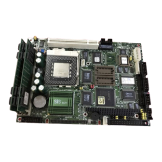
- Page 1 PCM-5862E/EL All in one multi-media Pentium processor-based single board computer with audio, SVGA, Ethernet and PCI expansion slot. User's Manual for PCM-5862E/EL...
- Page 2 For more information on this and other Advantech products please visit our website at: http://www.advantech.com http://www.advantech.com/epc For technical support and service for please visit our support website at: http://support.advantech.com This manual is for the PCM-5862E/EL Rev. A102-1 or higher Part No. 2006586202 2nd Edition Printed in Taiwan Jan. 1999...
- Page 3 Packing list Before you begin installing your card, please make sure that the following materials have been shipped: • 1 PCM-5862E/5862EL All-in-One Single Board Computer • 2 Ethernet driver disk • 2 utility disks with PCI SVGA utility programs and drivers for Windows 3.1, Windows 95, Windows NT 4.0, and OS/2...
-
Page 4: Table Of Contents
Features ..................... 3 Specifications .................... 3 Standard SBC functions ..............3 PCI SVGA/flat panel interface: ............4 Audio function: (PCM-5862E only) ..........4 PCI Bus Ethernet Interface: ............5 Mechanical and environmental ............5 Board layout and dimensions ..............5 Chapter 2 Installation ........7... - Page 5 Front panel connector (CN7) ..............20 Speaker ..................21 LED interface ................21 Watchdog output ................21 Reset switch .................. 21 Power connectors (CN6, CN10, CN14) ..........21 Peripheral power connector, -5V, -12V (CN10) ......21 Main power connector, +5V, +12V (CN14) ......... 21 Fan power supply connector (CN6) ..........
- Page 6 Connections to PLANAR EL (640 x 480 AD4 EL) ..............35 Connections to Toshiba LTM10C042 (640 x 480 TFT Color LCD) ............36 Connections to Sharp LM64C142 (640 x 480 DSTN Color LCD) ............. 37 Connections to Toshiba LTM12C275A (800 x 600 TFT Color LCD) ............38 Ethernet software configuration ............
- Page 7 Panning Drivers ................59 Linear Acceleration Drivers ............59 Windows 95 Drivers Setup Procedure ..........59 Windows NT Drivers Setup Procedure ..........60 OS/2 Drivers Setup Procedure .............. 61 Preliminary Steps ................61 Installing from Diskette ..............61 Selecting Monitor Type ..............63 Selecting Screen Resolution/Refresh Rate ........
- Page 8 IRQ mapping chart ................104 Appendix D Optional Extras ......105 Optional LCD Cables for 9.4" MONO, 10.4" TFT LCD Panel ..107 Optional USB cable ................107 Optional IrdA adapter ................. 107 Appdendix E Mechanical Drawing ....109 PCM-5862E/EL Mechanical Drawing ..........110...
-
Page 9: Chapter 1 General Information
General Information This chapter gives background information on the PCM-5862E/5862EL Sections include: • Introduction • Features • Specifications • Board layout and dimensions... -
Page 10: Introduction
EMI. Highly integrated multi-media SBC The PCM-5862E/5862EL is a highly integrated multi-media SBC that combines audio, video, and network functions on a single computer board the size of a 5.25" floppy drive. It provides 16-bit half-duplex, 8-bit full-duplex, integrated 3D audio and up to 1024 x 768 resolution @ 64K colors with 2MB display memory. -
Page 11: Features
Features • Accepts Intel MMX Pentium, AMD K6, and Cyrix 6x86MX, IDT WinChip C6 • 32-bit PCI-bus SVGA/LCD controller supports LCD & CRT display • 100/10Base-T Ethernet interface, IEEE 802.3U compatible • 16-bit audio interface, Sound Blaster Pro compatible • 4 serial ports (three RS-232 and one RS-232/422/485) •... -
Page 12: Pci Svga/Flat Panel Interface
• Display resolution: Supports non-interlaced CRT and LCD display up to 1024 x 768 @ 256 colors with 1MB VGA memory or 1024 x 768 @ 64 K colors with 2MB(PCM-5862E only) Audio function: (PCM-5862E only) • Chipset: ESS 1868 or 1869 •... -
Page 13: Pci Bus Ethernet Interface
• Operating temperature: 0 to 60° C (32 to 140° F) • Size: 203 mm (L) x 146 mm (W) (8" x 5.75") • Weight: 0.32 kg (0.7 lbs.) (w/o package) Board layout and dimensions PCM-5862E/5862EL dimensions Chapter 1 General Information... - Page 14 PCM-5862E/EL User's Manual...
-
Page 15: Chapter 2 Installation
Installation This chapter tells how to set up the PCM- 5862E/5862EL hardware, including instructions on setting jumpers and connecting peripherals, switches and indicators. Be sure to read all the safety precautions before you begin the installation procedure. Chapter 2 Installation... -
Page 16: Jumpers
Jumpers The PCM-5862E/5862EL has a number of jumpers that allow you to configure your system to suit your applications. The table below lists the function of each of the board’s jumpers. Jumpers Label Function CPU voltage setting Pentium MMX enable/disable... -
Page 17: Connectors
Connectors On-board connectors link the PCM-5862E/5862EL to external devices such as hard disk drives, a keyboard, or floppy drives. The table below lists the function of each of the board’s connectors. Connectors Label Function CRT display connector Flat panel display connector... -
Page 18: Locating Jumpers
Locating jumpers PCM-5862E/EL User's Manual... -
Page 19: Locating Connectors
Locating connectors CN19 CN17 CN15 CN18 CN14 CN13 CN12 CN16 CN11 CN10 CON1 CON2 Chapter 2 Installation... -
Page 20: Setting Jumpers
If you have any doubts about the best hardware configuration for your application, contact your local distributor or sales representative before you make any changes. Generally, you simply need a standard cable to make most connections. PCM-5862E/EL User's Manual... -
Page 21: Cpu Installation And Upgrading
Install a CPU in the ZIF socket PCM-5862E/5862EL provides a Zero Insertion Force (ZIF) socket for easy CPU installation. 1. Make sure the ZIF socket lever is in the upright position. To raise the lever, pull it out to the side a little and raise it as far as it will go. -
Page 22: System Clock Setting (J1, J2, And J4)
Refer to the CPU Speed Reference Table (below) for instructions on adjusting the internal clocks according to the base CPU speed. CPU Speed Reference Table CPU Speed (MHz) 266 300 Clock setting Frequency ratio PCM-5862E/EL User's Manual... -
Page 23: System/Pci Clock Setting
System/PCI clock setting System 50MHz 50MHz 60MHz *66MHz 75MHz 25MHz 33.3MHz 30MHz *33.3MHz 32MHz CPU frequency ratio 1.5/3.5 5 (Reserve) 5.5(Reserve) J4 cont. Pentium MMX(P55C) enabled/disabled (JP2) P55C enabled *P55C disabled * default setting Chapter 2 Installation... -
Page 24: Cpu Voltage Setting (Jp1)
3.50V closed closed closed closed M1 cache linear mode setting (J5) PCM-5862E/5862EL supports Cyrix M1 CPU with its linear access mode on L2 cache. This mode is set through J5. M1 cache linear mode enabled/disabled Enabled *Disabled * default setting... -
Page 25: Cmos Clear (J6)
Disabled * default setting Installing DRAM (SIMMs) The PCM-5862E/5862EL CPU card provides two 72-pin SIMM (Single In-line Memory Module) sockets and supports either Fast Page Mode (FPM) or Extended Data Output (EDO) DRAM with a speed of 70 ns or faster. You can install from 8 MB to 128 MB of RAM. -
Page 26: Ide Hard Drive Connector (Cn17)
4. Repeat steps 2 and 3 for each module you install. IDE hard drive connector (CN17) You can attach one or two Enhanced Integrated Device Electronics hard disk drives to the PCM-5862E/5862EL’s internal controller. The PCM-5862E/5862EL’s IDE controller uses a PCI local-bus interface. This advanced IDE controller supports faster data transfer, PID mode 3, mode 4. -
Page 27: Floppy Drive Connector (Cn18)
Floppy drive connector (CN18) You can attach up to two floppy drives to the PCM-5862E/ 5862EL’s on-board controller. You can use any combination of 5¼” (360 KB and 1.2 MB) and/or 3½” (720 KB, 1.44 MB, and 2.88 MB) drives. -
Page 28: Parallel Port Connector (Cn19)
Front panel connector (CN7) Next, you may want to install external switches to monitor and control the PCM-5862E/5862EL. These features are optional — install them only if you need them. The front panel connector (CN7) is an 8-pin male, dual in-line header and provides connections for a speaker, hard disk access indicator, watchdog output and an input switch for resetting the card. -
Page 29: Speaker
Speaker The PCM-5862E/5862EL can drive an 8 Ω speaker at 0.5 watts. Ensure that alternatives to this specification do not overload the card. LED interface The front panel LED indicator for hard disk access is an active low signal (24 mA sink rate). -
Page 30: Atx Power Control Connector (Con1, Con2)
ATX Power Control Connector (CON1, CON2) ATX feature connector (CON1) and soft power switch connector (CON2) The PCM-5862E/5862EL can support an advanced soft power switch function if an ATX power supply is used. To enable the soft power switch function: 1. -
Page 31: Atw Power Enable/Disable Setting(J17)
CD audio input connector (CN8) All CD-ROM drives can provide analog audio signal output when used as a music CD player. The CN8 on PCM-5862E/5862EL is a connector to input CD audio signal into the audio controller. The audio cable of your CD-ROM drive will be used to connect to CN8. -
Page 32: Audio Power Source Setting
Audio power source setting (J16) The PCM-5862E/5862EL is designed to work with a single +5V power supply. The audio interface can also function normally under single +5V power supply, but most audio controllers require an independent power source generated from a +12V power. The independent power source avoids the noise from the other digital circuits. -
Page 33: Com-Port Connector (Cn16)
COM-port connector (CN16) The PCM-5862E/5862EL provides four serial ports (COM1, 3, 4: RS-232; COM2: RS-232/422/485) in one COM port connector. The COM port connector is a 40-pin, dual-in-line, male header and provides connections for serial devices (a mouse, etc.) or a communication network. -
Page 34: Com3/Com4 Ri Pin Setting (J11, J12)
The IRQ and the address range for COM1, 2, 3, 4 are fixed. However, if you wish to disable the port or change these parameters later you can do this in the system BIOS setup. The table below shows the settings for the PCM-5862E/5862EL’s serial ports. PCM-5862E/5862EL serial port default settings Port... -
Page 35: Vga Interface Connections
Ensure that both CN10 and CN14 are connected for ±12 V power supply. The PCM-5862E/5862EL provides a bias control signal on CN2 that can be used to control the LCD bias voltage. It is recommended that the LCD bias voltage not be applied to the panel until the logic supply voltage (+5V or +3.3V) and panel video signals are stable. -
Page 36: Lcd Power Setting (J10)
LCD power setting (J10) The PCM-5862E/5862EL’s PCI SVGA interface supports 5V and 3.3V LCD displays. By changing the setting of J10, you can select the panel video signal level to be 5V or 3.3V. LCD power setting *5 V 3.3 V... -
Page 37: Ethernet Configuration
Ethernet configuration The PCM-5862E/5862EL is equipped with a high performance 32- bit PCI-bus Ethernet interface which is fully compliant with IEEE 802.3U 10/100Mbps CSMA/CD standards. It is supported by all major network operating systems and is 100% Novell NE-2000 compatible. -
Page 38: Watchdog Timer Configuration
When the watchdog timer activates (CPU processing has come to a halt), it can reset the system or generate an interrupt on IRQ15. This can be set via setting J13 as shown below: Watchdog timer action *System reset IRQ15 * default setting PCM-5862E/EL User's Manual... -
Page 39: Usb Connectors (Cn4, Cn5)
USB connectors (CN4, CN5) The PCM-5862E/5862EL board provides two USB (Universal Serial Bus) interfaces which gives complete plug and play, hot attach/detach for up to 127 external devices. The USB interfaces comply with USB specification rev. 1.0 and are fuse protected. - Page 40 PCM-5862E/EL User's Manual...
-
Page 41: Chapter 3 Software Configuration
Software Configuration This chapter details the software configuration information. It shows you how to configure the card to match your application requirements. AWARD System BIOS is covered in Chapter 4. Sections include: • Introduction • Connections for four standard LCDs •... -
Page 42: Introduction
Introduction The PCM-5862E/5862EL system BIOS and custom drivers are located in a 256 Kbyte, 32-pin (JEDEC spec.) Flash ROM device, designated U19. A single Flash chip holds the system BIOS, VGA BIOS, and network Boot ROM image. The display can be configured via CMOS settings. -
Page 43: Connections To Planar El (640 X 480 Ad4 El)
Connections to PLANAR EL (640 x 480 AD4 EL) PLANAR 640 x 480 AD4 PCM-5862E/5862EL CN2 Pin name Pin name — — — — — — — — VCLK ASHFCLK /BLANK — — — — — — SELFTST COLMAP ENABLE —... -
Page 44: Connections To Toshiba Ltm10C042 (640 X 480 Tft Color Lcd)
Connections to Toshiba LTM10C042 (640 x 480 TFT Color LCD) LTM10C042 PCM-5862E/5862EL CN2 Pin name Pin name SHFCLK ENAB 31,32 PCM-5862E/EL User's Manual... -
Page 45: Connections To Sharp Lm64C142 (640 X 480 Dstn Color Lcd)
Connections to Sharp LM64C142 (640 x 480 DSTN Color LCD) LM64C142 PCM-5862E/5862EL CN2 Pin name Pin name CN1-1 CN1-2 CN1-3 SHFCLK CN1-4 DISP CN1-5 CN1-6 CN1-7 — +27* CN1-8 CN1-9 CN1-10 CN1-11 CN1-12 CN1-13 CN1-14 CN1-15 CN2-1 CN2-2 CN2-3 CN2-4... -
Page 46: Connections To Toshiba Ltm12C275A (800 X 600 Tft Color Lcd)
Connections to Toshiba LTM12C275A (800 x 600 TFT Color LCD) LTM12C275A PCM-5862E/5862EL CN2 Pin name Pin name NCLK SHFCLK ENAB M/DE +5 V +5 V PCM-5862E/EL User's Manual... -
Page 47: Ethernet Software Configuration
To configure the medium type, to view the current configuration, or to run diagnostics, do the following: 1. Power the PCM-5862E/5862EL on. Ensure that the RSET8139.EXE file is located in the working drive. 2. At the prompt type RSET8139.EXE and press <Enter>. The Ethernet configuration program will then be displayed. - Page 48 PCM-5862E/EL User's Manual...
-
Page 49: Chapter 4 Award Bios Setup
Award BIOS Setup This chapter describes how to set BIOS configuration data. Chapter 4 Award Bios Setup... -
Page 50: System Test And Initialization
3. The CMOS memory has lost power and the configuration information has been erased. The PCM-5862E/5862EL’s CMOS memory has an integral lithium battery backup. The battery backup should last ten years in normal service, but when it finally runs down, you will need to replace the complete unit. -
Page 51: Award Bios Setup
AWARD BIOS setup Award’s BIOS ROM has a built-in Setup program that allows users to modify the basic system configuration. This type of information is stored in battery-backed CMOS RAM so that it retains the Setup information when the power is turned off. Entering setup Power on the computer and press <Del>... -
Page 52: Standard Cmos Setup
This standard Setup Menu allows users to configure system components such as date, time, hard disk drive, floppy drive and display. Once a field is highlighted, on-line help information is displayed in the left bottom of the Menu screen. CMOS setup screen PCM-5862E/EL User's Manual... -
Page 53: Bios Features Setup
BIOS features setup By choosing the BIOS FEATURES SETUP option from the INITIAL SETUP SCREEN menu, the screen below is displayed. This sample screen contains the manufacturer’s default values for the PCM-5862E/5862EL. BIOS features setup Chapter 4 Award Bios Setup... -
Page 54: Chipset Features Setup
CHIPSET features setup By choosing the CHIPSET FEATURES SETUP option from the INITIAL SETUP SCREEN menu, the screen below is displayed. This sample screen contains the manufacturer’s default values for the PCM-5862E/5862EL. CHIPSET features setup PCM-5862E/EL User's Manual... -
Page 55: Power Management Setup
Power management setup By choosing the POWER MANAGEMENT SETUP option from the INITIAL SETUP SCREEN menu, the screen below is displayed. This sample screen contains the manufacturer’s default values for the PCM-5862E/5862EL. Power management setup Chapter 4 Award Bios Setup... -
Page 56: Pnp/Pci Configuration
PnP/PCI Configuration By choosing the PnP/PCI CONFIGURATION option from the Initial Setup Screen menu, the screen below is displayed. This sample screen contains the manufacturer’s default values for the PCM-5862E/5862EL. PnP/PCI Configuration PCM-5862E/EL User's Manual... -
Page 57: Integrated Peripherals
By choosing the INTEGRATED PERIPHERALS option from the INITIAL SETUP SCREEN menu, the screen below is displayed. This sample screen contains the manufacturer’s default values for the PCM-5862E/5862EL. The PANEL TYPE by default supports a 18-bit 640 x 480 TFT LCD panel display. Integrated Peripherals... -
Page 58: Load Bios Defaults
LOAD BIOS DEFAULTS loads the default system values directly from ROM. If the stored record created by the Setup program becomes corrupted (and therefore unusable), these defaults will load automatically when you turn the PCM-5862E/5862EL on. Load BIOS defaults screen PCM-5862E/EL User's Manual... -
Page 59: Change Password
Change Password To change the password, choose the PASSWORD SETTING option form the Setup main menu and press <Enter>. 1. If the CMOS is bad or this option has never been used, a default password is stored in the ROM. The screen will display the following messages: Enter Password: Press <Enter>. -
Page 60: Auto Detect Hard Disk
This record is required for the system to operate. Exit without saving Selecting this option and pressing <Enter> lets you exit the Setup program without recording any new values or changing old ones. PCM-5862E/EL User's Manual... -
Page 61: Chapter 5 Pci Svga Setup
PCI SVGA Setup The PCM-5862E/5862EL features an on- board PCI flat panel/VGA interface. This chapter provides instructions for installing and operating the software drivers on the included display driver diskette. Chapter 5 PCI VGA Setup... -
Page 62: Before You Begin
The enhanced display drivers for the PCM-5862E/5862EL board are located on the software installation diskette. You must install the drivers and utility software by using the supplied SETUP program for DOS... -
Page 63: Simultaneous Display Mode
(multisync) monitors are supported as analog monitors. Both CRT and panel displays can be used simultaneously. The PCM-5862E/5862EL can be set in one of three configurations: on a CRT, on a flat panel display, or on both simultaneously. The system is initially set to simultaneous display mode. In the utility diskette, there are three .COM files that can be used to select the... -
Page 64: Driver Installation
The display driver diskette contains drivers for several versions of certain applications. You must install the correct version in order for the driver to work properly so make sure you know which version of the application you have. PCM-5862E/EL User's Manual... -
Page 65: Windows Setup
Windows setup These drivers are designed to work with Microsoft Windows 3.1. You may install these drivers through Windows or in DOS. Step 1: Install Windows as you normally would for a VGA display. Run Windows to make sure that it is working correctly. Step 2: Place the display driver diskette in drive A. -
Page 66: Dos Setup
Step 5: Follow the directions on the screen to complete the setup. In most cases, you may press <ENTER> to accept the suggested option. When Setup is done, it will return to DOS. Type WIN <ENTER> to start Windows with the new display driver. PCM-5862E/EL User's Manual... -
Page 67: Changing Display Drivers In Dos
Changing Display Drivers in DOS To change display drivers from DOS, change to the Windows directory and run Setup, repeating steps 4 and 5 from the previous page. Besides the special display drivers marked by an asterisk (*), you should be able to use the following standard drivers: 640x480, 16 colors Super VGA 800x600, 16 colors... -
Page 68: Windows Nt Drivers Setup Procedure
2. Click on Test to test the newly selected graphics mode. A color test screen should appear, followed by the Testing Mode window. 3. Click on Yes to continue. The Display Settings Change window will appear. 4. Click on Restart Now for the new settings to take effect. PCM-5862E/EL User's Manual... -
Page 69: Os/2 Drivers Setup Procedure
OS/2 Drivers Setup Procedure Preliminary Steps The following steps must be performed before you install the 65550/554 display driver: 1. OS/2 DOS Support must be installed. 2. If you previously installed SVGA support, you must reset the system to VGA mode. VGA is the default video mode enabled when OS/2 is installed. - Page 70 Make sure to remove the install diskette before restarting the system. When the system has restarted, the display driver will be initialized for 640x480x256 Color, 60Hz refresh. To switch to a different video resolution color depth, or refresh rate, follow the steps below. PCM-5862E/EL User's Manual...
-
Page 71: Selecting Monitor Type
Selecting Monitor Type Monitor type is initially set to DEFAULT. This DEFAULT setting may not allow you to select all resolution/refresh combinations that are available for your monitor. The following steps can be done to select monitor type. This section applies only after installation, or when a different monitor is used. -
Page 72: Installation Notes
“corrupted” display. This is normal, as the configuration process is doing Video BIOS mode sets to determine which screen resolutions BIOS supports. This configuration information is then used to provide the System-Settings Resolution and Refresh selections. PCM-5862E/EL User's Manual... -
Page 73: Chapter 6 Audio Setup
Audio Setup The PCM-5862E/5862EL is equipped with an audio interface that records and playback CD-quality audio. This chapter provides instructions for installing the software drivers on the included audio driver diskettes. Chapter 6 Audio Setup... -
Page 74: Introduction
Introduction The PCM-5862E/5862EL on board audio interface provides high- quality stereo sound and FM music synthesis (ESFM) by using the ES1868 or ES1869 audio controller from ESS Technology, Inc. The audio interface can record, compress, and play back voice, sound, and music with built-in mixer control. -
Page 75: Controlling Volume In Dos
Controlling volume in DOS The ES1868/1869 audio controller provides software control on the setting of audio volumes. The VOLUME CONTROL utility located in the UTILITY subdirectory of audio driver diskette is used to control the volume setting in DOS. To control the volume setting, simply type the ESSVOL at the DOS prompt with appropriate parameters. -
Page 76: Driver Installation
To facilitate the installation of the audio drivers, you should read the instructions in this chapter carefully before you attempt installation. The audio drivers for the PCM-5862E/5862EL board are located on the audio driver diskettes. You must install the drivers by using the supplied SETUP program. -
Page 77: Windows 95 Drivers
Windows 95 Drivers 1. Boot your system and place the audio driver diskette in drive 2. Select Add New Hardware from Windows‘s Control Panel. 3. Click Next to bring up the Windows search for new hardware setup screen. 4. Select No and click Next button. 4. - Page 78 PCM-5862E/EL User's Manual...
-
Page 79: Chapter 7 Pci Bus Ethernet
PCI Bus Ethernet Interface This chapter provides information on Ethernet configuration. • Introduction • Installation of Ethernet Driver Installation for MS-DOS & WINDOWS 3.1 Installation for WINDOWS 95 Installation for WINDOWS NT • Further Information... -
Page 80: Introduction
Installation of Ethernet Driver Before installing the Ethernet driver, note the procedures below. You must know which operating system you are using in your PCM-5862E/EL, and then refer to the corresponding installation flow chart. Then just follow the steps described in the flow chart. You will quickly and successfully complete the installation, even if you are not familiar with instructions for MS-DOS or WINDOWS. -
Page 81: Installation For Windows 95
Chapter 7 PCI Bus Ethernet Interface... - Page 82 Insert disc labled a. Insert the disc into RTL8139A Driver the CD-ROM drive. #2 into drive A: b. Fill in the correct path. c. Click "OK". D:\Lan\ A:\Win95\ a. Choose the "Realtek" item. b. Click "OK". a. Make sure the configurations of relative items are set correctly.
-
Page 83: Installation For Windows Nt
Chapter 7 PCI Bus Ethernet Interface... - Page 84 Insert disc labled a. Insert the disc into RTL8139A Driver the CD-ROM drive. #2 into drive A: b. Fill in the correct path. c. Press the "OK" button. D:\Lan\ A:\Winnt\ a. Choose the "Realtek" item. b. Press the "OK" button. a.
-
Page 85: Further Information
Chapter 7 PCI Bus Ethernet Interface... - Page 86 PPC-120/140 User's Manual...
-
Page 87: Appendix A Programming The Watchdog Timer
Programming the Watchdog Timer The PCM-5862E/5862EL is equipped with a watchdog timer that resets the CPU or generates an interrupt if processing comes to a standstill for whatever reason. This feature ensures system reliability in industrial standalone, or unmanned, environments. -
Page 88: Programming The Watchdog Timer
REM Your application task #2 OUT &H443, data REM Reset the timer X=INP (&H443) REM Disable the watchdog timer 1000 REM Subroutine #1, you application task 1070 RETURN 2000 REM Subroutine #2, you application task 2090 RETURN PCM-5862E/EL User's Manual... -
Page 89: Appendix B Installing Pc/104 Modules
Installing PC/104 Modules This appendix gives instructions for installing PC/104 modules. Appendix B Installing PC/104 Modules... -
Page 90: B.1 Installing Pc/104 Modules
B.1 Installing PC/104 modules The PCM-5862E/5862EL's PC/104 connectors give you the flexibility to attach PC/104 modules. Installing these modules on the PCM-5862E/5862EL is quick and simple. The following steps show how to mount the PC/104 modules: 1. Remove the PCM-5862E/5862EL from your system paying particular attention to the safety instructions already mentioned above. - Page 91 P C / 1 0 4 M o u n t i n g S u p p o r t M a l e F e m a l e P C / 1 0 4 m o d u l e P C A - 6 1 5 4 / L Figure B-1: PC/104 module mounting diagram 82.5...
- Page 92 PCM-5862E/EL...
-
Page 93: Appendix C Pin Assignments
Pin Assignments This appendix contains information of a detailed or specialized nature. It includes: • CRT display connector • Flat panel display connector • PC/104 connectors • USB connectors • Fan power connector • Front panel connector • CD audio connector •... -
Page 94: Crt Display Connector (Cn1)
CRT display connector (CN1) 15 13 11 9 7 5 3 1 16 14 12 10 8 6 4 2 PCM-5862E/5862EL CRT display connector Signal Signal SIGNAL GND H-SYNC GREEN CHASSIS GND SIGNAL GND V-SYNC BLUE CHASSIS GND CHASSIS GND... -
Page 95: Flat Panel Display Connector (Cn2)
Flat panel display connector (CN2) • • • • • 42 44 • • • • • 41 43 PCM-5862E/5862EL Flat panel display connector Function Function +12 V +12 V 5V/3.3V 5V/3.3V ENAVEE SHFCLK ENABKL ASHFCLK ENAVDD* 5V/3.3V * High active... -
Page 96: Pc/104 Connectors (Cn3, Cn9)
Row B • • • • • 31 32 • • • • • 19 20 Row C Row D • • • • • 19 20 PCM-5862E/5862EL PC/104 connectors Signal (CN3) Signal (CN9) Number RowA RowB RowA RowB IOCHCHK*... - Page 97 PCM-5862E/5862EL PC/104 connectors (cont.) Signal (CN3) Signal (CN9) Number RowA RowB RowA RowB SA13 DRQ1 SD14 MASTER* SA12 REFRESH* SD15 SA11 SYSCLK (KEY) SA10 IRQ7 — — IRQ6 — — IRQ5 — — IRQ4 — — IRQ3 — — DACK2* —...
-
Page 98: Usb Connectors (Cn4, Cn5)
USB connectors (CN4, CN5) 4 3 2 1 PCM-5862E/5862EL USB connector Signal +5 V Fan power connector (CN6) 3 2 1 PCM-5862E/5862EL Fan power connector Signal +5 V +12 V PCM-5862E/EL User's Manual... -
Page 99: Front Panel Connector (Cn7)
Front panel connector (CN7) 1 3 5 7 2 4 6 8 PCM-5862E/5862EL Front panel connector Signal HDD LED- (HARD DISK ACTIVE) HDD LED+ (V SPEAKER+ SPEAKER- (GND) WATCHDOG OUTPUT* RESET SWITCH- (GND) RESET SWITCH+ * Low active Appendix C Pin Assignments... -
Page 100: Cd Audio Connector (Cn8)
CD audio connector (CN8) 4 3 2 1 PCM-5862E/5862EL CD audio connector Signal CD AUDIO L CD AUDIO R Peripheral power connector (CN10) PCM-5862E/5862EL Peripheral power connector Function -5 V -12 V PCM-5862E/EL User's Manual... -
Page 101: Ethernet 10Base-T Connector (Cn11)
Ethernet 10/100 BASE-T connector (CN11) 9 7 5 3 10 8 6 4 PCM-5862E/5862EL Ethernet 10BASE-T connector Signal CRS LED RCV+ RCV- BNC LED XMT+ XMT- IR connector (CN12) 5 4 3 2 PCM-5862E/5862EL IR connector Signal IR IN IR OUT... -
Page 102: Audio Connector (Cn13)
SPEAKER OUT R+ SPEAKER OUT R- SPEAKER OUT L+ SPEAKER OUT L- LINE OUT R LINE OUT L LINE IN R LINE IN L MIC IN Main power connector (CN14) PCM-5862E/5862EL Main power connector Signal +12 V +5 V PCM-5862E/EL User's Manual... -
Page 103: Keyboard And Ps/2 Mouse Connector (Cn15)
Keyboard and PS/2 mouse connector (CN15) PCM-5862E/5862EL Keyboard and mouse connector Signal MS VCC MS DATA MS CLOCK KB VCC KB DATA KB CLOCK Appendix C Pin Assignments... -
Page 104: Com Port Connector (Cn16)
COM port connector (CN16) 39 37 • • • • • 40 39 • • • • • PCM-5862E/5862EL COM port connector Signal Signal RLSD1 DSR1 RTS1 CTS1 DTR1 RLSD2 DSR2 RTS2 CTS2 DTR2 RLSD3 DSR3 RTS3 CTS3 DTR3 RLSD4... - Page 105 Note: The cable of serial port (CN16) comes with four DSUB- 9 male connectors. The pin assignments of each DSUB- 9 connector are listed below for your reference: DSUB-9 Conn.(RS-232) mode RS-422 mode RS-485 module Signal Signal Signal DATA- DATA+ Appendix C Pin Assignments...
-
Page 106: Ide Hard Drive Connector (Cn17)
IDE hard drive connector (CN17) • • • • • • • • • • PCM-5862E/5862EL IDE hard drive connector Signal Signal IDE RESET* DATA 7 DATA 8 DATA 6 DATA 9 DATA 5 DATA 10 DATA 4 DATA 11... -
Page 107: Floppy Drive Connector (Cn18)
Floppy drive connector (CN18) • • • • • • • • • • PCM-5862E/5862EL Floppy drive connector Signal Signal DENSITY SELECT* DRIVE TYPE INDEX* MOTOR 0* DRIVE SELECT 1* DRIVE SELECT 0* MOTOR 1* DIRECTION* STEP* WRITE DATA* WRITE GATE*... -
Page 108: Parallel Port Connector (Cn19)
Parallel port connector (CN19) • • • • • • • • • • PCM-5862E/5862EL Parallel port connector Signal Signal STROBE* AUTOFD* INIT* SLCTINI* ACK* BUSY SLCT * Low active PCM-5862E/EL User's Manual... -
Page 109: Atx Power Feature Connector (Con1)
ATX Power Feature Connector (CON1) PCM-5862E/5862EL ATX Feature Connector Signal VPSON N.C. 5VSB (stand by voltage) ATX Soft Power Switch Connector (CON2) PCM-5862E/5862EL ATX Soft Switch Connector Signal SWITCH Appendix C Pin Assignments... - Page 110 System I/O Ports PCM-5862E/5862EL System I/O ports Addr. range (Hex) Device 000-01F DMA controller 020-021 Interrupt controller 1, master 022-023 Chipset address 040-05F 8254 timer 060-06F 8042 (keyboard controller) 070-07F Real-time clock, non-maskable interrupt (NMI) mask 080-09F DMA page register,...
-
Page 111: 1St Mb Memory Map
1st MB Memory Map PCM-5862E/5862EL 1st MB memory map Addr. range (Hex) Device F000h - FFFFh System ROM DC00h - EFFFh Unused *CC00h - DBFFh Ethernet ROM C000h - CBFFh Expansion ROM B800h - BFFFh CGA/EGA/VGA text B000h - B7FFh... -
Page 112: Irq Mapping Chart
IRQ mapping chart PCM-5862E/5862EL IRQ mappingg ch5862E/5862ELction 5862E/5862ELer Keyboard Interrupt from Controller 2 COM2 COM1 COM4 LPT1 Reserved (Audio) COM3 Reserved (Ethernet) PS/2 mouse INT from co-processor Primary IDE Watchdog Timer * Ethernet interface IRQ select: 9, 11, 12, 15... -
Page 113: Appendix D Optional Extras
Optional Extras Appendix D Optional Extras... - Page 114 PCM-10586-2 Cable kit for PCM-5862E/5862EL The PCM-5862E/5862EL requires several cables for normal operation. You can make them yourself or purchase an optional cable kit assembly, which includes the following: Part No. Cable Description PCM-5862EL Terminating Connector Connector 1701440350 2.5“ and 1.8” IDE,...
-
Page 115: Optional Lcd Cables For 9.4" Mono, 10.4" Tft Lcd Panel
Optional LCD Cables for 9.4" MONO, 10.4" TFT LCD Panel Optional LCD Cables for 9.4" MONO, 10.4" TFT LCD Panel Part No. Cable Description Panel Type 1700090501 Cable DF9 (2 mm) 50 cm Toshiba LTM10C042 1700090403 Cable DF9 (2 mm) 40 cm Sharp LM64183P Sharp LM64P89 1703440151... - Page 116 PCA-582E/EL User's Manual...
-
Page 117: Appdendix E Mechanical Drawing
Mechanical Drawing Appendix E Mechanical Drawing... -
Page 118: Pcm-5862E/El Mechanical Drawing
PCM-5862E/EL Mechanical Drawing Figure E-1: PCM-5862E/EL Mechanical Drawing PCA-582E/EL User's Manual...
Need help?
Do you have a question about the PCM-5862E and is the answer not in the manual?
Questions and answers