
Related Manuals for Emerson FloBoss S600


Summary of Contents for Emerson FloBoss S600
- Page 1 Form Number A6115 Part Number D301150X412 January 2007 ™ FloBoss S600 Flow Manager Instruction Manual Remote Automation Solutions...
-
Page 2: January 2007
ROCLINK is a trademark of one of the Emerson Process Management companies. The Emerson logo is a trademark and service mark of Emerson Electric Co. All other marks are the property of their respective owners. © 2001-2007 Remote Automation Solutions, division of Emerson Process Management. All rights reserved. -
Page 3: Table Of Contents
Contents Chapter 1 – General Information Scope of Manual.......................1-1 FloBoss S600 Flow Manager ...................1-2 Config600 Configuration Software ...................1-5 1.3.1 Config600 Lite ....................1-5 1.3.2 Config600 Lite+ ....................1-5 1.3.3 Config600 Pro ....................1-6 Related Specification Sheets....................1-6 Chapter 2 – Installation Preparing for Installation....................2-1 Environmental Considerations..................2-2... -
Page 4: Startup
4.2.3 Turbine Pulse Inputs ..................4-21 4.2.4 Pulse Outputs (PULSEOUT) ................4-22 4.2.5 Frequency Inputs....................4-22 4.2.6 P154 Prover Bit Links (Jumpers) ..............4-24 P188 HART Board......................4-25 Chapter 5 – Front Panel Description........................5-1 Front Panel Port........................5-2 Keypad..........................5-2 5.3.1 F Keys ........................5-2 5.3.2 Direction and Menu Keys ...................5-3 5.3.3 Numeric Keys .....................5-3 5.3.4... -
Page 5: Front Panel
8.3.6 Upgrading the BIOS ...................8-8 Appendix A – Glossary Appendix B – Front Panel Navigation Main Menu ........................B-1 Flow Rates Menu......................B-2 Totals Menu ........................B-2 Operator Menu......................... B-3 Plant I/O Menu......................... B-4 System Settings Menu..................... B-4 Tech/Engineer Menu ....................... B-5 Calculations Menu ...................... - Page 6 Revised Jan-07...
-
Page 7: Chapter 1 - General Information
This chapter details the structure of this manual and provides an overview of the S600 and its components. In This Chapter Scope of Manual................. 1-1 FloBoss S600 Flow Manager ............. 1-2 Config600 Configuration Software............1-5 1.3.1 Config600 Lite................ 1-5 1.3.2 Config600 Lite+ .............. -
Page 8: Floboss S600 Flow Manager
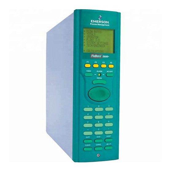
FloBoss S600 Flow Manager Figure 1-1. The FloBoss S600 Flow Manager The FloBoss S600 Flow Manager is a panel-mount flow computer designed specifically to measure hydrocarbon liquid and gas where versatility and accuracy matter. The S600’s standard features make it ideal for fiscal measurement, custody transfer, batch loading, and meter proving applications. -
Page 9: Cpu Board
S600 Instruction Manual protection with a detailed event log for audit purposes (supports ® ® Windows Internet Explorer Version 6 or greater). Two configurable EIA-232 (RS-232) serial ports. Three EIA-422/485 (RS-422/RS-485) serial ports (up to 38400 bps baud) for connection to intelligent meters, Modbus SCADA data networks, DCS Supervisory Systems, and so on. - Page 10 S600 Instruction Manual Figure 1-3. Intelligent I/O Board You can manage a configuration through the front panel interface or create a configuration through configuration software (Config600) running on a personal computer (PC). The front panel interface consists of a backlit LCD display, a 29-button keypad, and an alarm status LED.
-
Page 11: Config600 Configuration Software
S600 Instruction Manual Config600 Configuration Software The Config600 configuration software is a suite of editors that enable you to monitor, configure, and calibrate the S600. The software has three versions: Config600 Lite, Config600 Lite+, and Config600 Pro. : The S600 will not operate until you send a configuration to it Note from the host PC. -
Page 12: Config600 Pro
S600 Instruction Manual With Config600 Lite+ you can: Create a new application from base templates for gas, liquid, and prover applications. Edit initialization process data, including orifice size, analog input scaling, alarm limits, and keypad values. Build and customize Modbus slave maps, Modbus master polling sequences, front panel displays, and period report formats. -
Page 13: Chapter 2 - Installation
S600 Instruction Manual Chapter 2 – Installation This chapter provides instructions on installing the FloBoss S600, including installation preparation, procedures for mounting the panels, and the installation and removal of plug-in boards. In This Chapter Preparing for Installation..............2-1 Environmental Considerations............2-2 Required Tools for Installation............ -
Page 14: Environmental Considerations
S600 Instruction Manual Figure 2-1. FloBoss S600 System Components Environmental Considerations The S600 panel mount is designed for use within the control room. Place it in a position that provides ease of use, comfort, and safety for operators and maintenance personnel. The optimum height for viewing and using the display and keypad is at operator eye level. -
Page 15: Installing The S600
S600 Instruction Manual Installing the S600 Refer to the following procedures for installing the various S600 components, including the front panel, panel-mounted unit, and plug-in board. 2.4.1 Unpacking the S600 Unpack the S600 carefully and inspect parts for visual damage. : Do not discard packaging material until after you have identified Note all pieces of the shipment and you are confident that all parts are... - Page 16 S600 Instruction Manual Figure 2-3. Lifted Front Panel Disconnect the ribbon cable from the back of the front panel at the blue connector (refer to Figure 2-4). Observe the orientation of the connector with its mating keyway. You must correctly re-insert the ribbon cable at the end of the installation process.
-
Page 17: Installing The Panel-Mounted Unit
S600 Instruction Manual Table 2-1. Mounting Dimensions Part Dimensions Display Keypad Molding 85 mm (3.35") width x 269 mm (10.59") height x 28 mm (1.10") deep Case 84.5 mm (3.327") width x 270 mm (10.63") height x 303.8 mm (11.94") deep Panel Cutout 66 mm (2.6") width x 150 mm (5.9") height... - Page 18 S600 Instruction Manual Figure 2-6. Panel Cutout Dimensions : The S600 fits into existing S500, 869 flow computer panel Note cutouts. Ensure a panel thickness of at least 3 mm (0.12 in) to prevent distortion. If you use a thinner panel, support the rear of the case (refer to Figure 2-7).
-
Page 19: Reinstalling The Front Panel
S600 Instruction Manual Place the front of the case against the rear of the prepared cutout. Re-install the top and bottom bosses and tighten with a 5.5 mm (5 BA) hex wrench. Once you have fitted the rear support, use a self-tapping screw to secure the case to the rear support. - Page 20 S600 Instruction Manual Ejectors Figure 2-8. Unscrewing the Retention Screws Unlatch the ejectors for the appropriate board and pull the board clear of the case. You may need to rock the board slightly to release the connectors (refer to Figures 2-9 and 2-10). Figure 2-9.
-
Page 21: Board Ready For Removal Or Insertion
S600 Instruction Manual Figure 2-10. Board Ready for Removal or Insertion To install a plug-in board: Carefully align the boards with the guides (located at the top and bottom of the case). Gently slide the board into the case until it mates fully with the appropriate connector on the backplane. - Page 22 S600 Instruction Manual 2-10 Installation Revised Jan-07...
-
Page 23: Chapter 3 - Cpu
S600 Instruction Manual Chapter 3 – CPU This chapter provides information on plug-in connector blocks and bit link (jumper) settings for the P152 CPU board. In This Chapter P152 CPU Board ................3-1 Power Supply..................3-3 3.2.1 Watchdog Relay ..............3-4 3.2.2 On-Board Battery Backup............ -
Page 24: P152 Cpu Board
S600 Instruction Manual TB-1 Power COM 4 COM 3 COM 1-2 Remote I/O TB-2 COM 5, 6, 7 RS-232/RS-485 Network Figure 3-1. P152 CPU Backplate Figure 3-2. P152 CPU Board Revised Jan-07... -
Page 25: Power Supply
S600 Instruction Manual P152 CPU NETWORK SERVICE SERVICE RJ45 TB - 1 + VE 24V DC SUPPLY + 24v ETHERNET + 15v COMPUTER ALARM COMM - 4 SERVICE RJ45 SIG GND REMOTE I/O SERVICE '9' D FEMALE TX + RESET RS232 10.SEL(1) RS485... -
Page 26: Watchdog Relay
S600 Instruction Manual The startup in-rush current may draw 6 Amps for approximately 100 milliseconds. This in-rush becomes significant when multiple flow computers are connected to the same power supply. An on-board anti-surge fuse (2.5 Amp rating) protects the supply line should a fault occur within the unit. -
Page 27: Communication Ports
S600 Instruction Manual Table 3-3. Battery Specifications Charging Time (20%-80%) 48 hours Hold-up Time (without recharge) 3 months at 20° C (68° F), 1 month at 40° C (104° F) Battery Life (Typical) 5-7 years Battery Backup Holdup Time (after battery has failed its 2 weeks at 20°... -
Page 28: Rs-422)/Eia-485 (Rs-485) Multi-Drop Port
S600 Instruction Manual Table 3-5. COM3 and COM4 Pin Connections Function Figure 3-4. Pin Connections The maximum cable length is a function of the baud rate and quality of cable used. For example, a maximum length of 15 m (50 ft) should be used at 19200 bps when using unscreened cable. -
Page 29: Ethernet Lan Port
S600 Instruction Manual Table 3-6. COM5, COM6, and COM7 Pin Connections Channel Function COM5 COM6 COM7 Signal Common 3.3.3 Ethernet LAN Port The standard Ethernet port on the CPU card’s backplate is for high- speed communications using an Ethernet Local Area Network (LAN) architecture. -
Page 30: Link Cable
S600 Instruction Manual Table 3-7. COM1-2 Pin Connections Function TX to R. Display SPEAKER OUT TX to PC RTS to PC RX from R. Display CTS to R. Display RX from PC CTS to PC A special serial cable is required to connect the host PC to the FloBoss Connecting to the S600 unit. -
Page 31: Cpu On-Board Connectors
S600 Instruction Manual CPU On-Board Connectors Table 3-8 shows the miscellaneous device connectors provided on the P152 CPU module. This information is for identification purposes only. Do not modify these connections unless told to do so by the factory. Table 3-8. Miscellaneous Device Connectors for the P152 CPU Module Socket Description DIN Backplane Connector... -
Page 32: Dual Ethernet Lan Port
S600 Instruction Manual Jumper (Link) Position Description Flash LK15 1-2/2-3 Block 0 - 1M - Write Prohibited (1-2) or Write Enabled (2-3) LK16 1-2/2-3 Block 1 - 2M - Write Prohibited (1-2) or Write Enabled (2-3) LK17 1-2/2-3 Block 2 - 3M - Write Prohibited (1-2) or Write Enabled (2-3) LK18 1-2/2-3... - Page 33 S600 Instruction Manual Figure 3-6. Dual Ethernet Communications Card The second Ethernet port is usually shipped from the factory pre- installed. If pre-installed, no hardware configuration or wiring is required. For field installation, the second Ethernet board is provided with a specialized backplate.
- Page 34 S600 Instruction Manual 3-12 Revised Jan-07...
-
Page 35: Chapter 4 - Input/Output (I/O)
S600 Instruction Manual Chapter 4 – Input/Output (I/O) This chapter provides information on plug-in connector blocks and field wiring (ANIN, PRT, and DPR signals). In This Chapter P144 I/O Board ................... 4-1 4.1.1 Analogue Inputs (ANIN)............4-3 4.1.2 Analogue Outputs (DAC)............4-5 4.1.3 Digital Inputs (DIGIN)............. -
Page 36: Digout
S600 Instruction Manual SKT-A ANIN 1-10 ANOUT 1-4 SKT-B ANIN 11-12 DIGIN 1-6 DIGOUT 1-2 Freq Inputs Pulse Outputs SKT-C DIGIN 7-16 DIGOUT 3-12 Turbine Inputs Figure 4-1. Backplate with P144 I/O Board Figure 4-2. P144 I/O Board Revised Jan-07... -
Page 37: Analogue Inputs (Anin)
S600 Instruction Manual P144 IIO 1 SERVICE SERVICE SKT A SKT A +15V ADC 1+ SUPPLY ADC 2+ DAC 1 OUTPUT ADC 3+ GROUND +15V 1 - 5 V ADC 4+ SUPPLY ADC 5+ DAC 2 OUTPUT LK16-20 GROUND +15V ADC 6+ SUPPLY ADC 7+... -
Page 38: Bit Links
S600 Instruction Manual to current using a bit link (jumper) on the board to place a high accuracy calibrated shunt resistor in parallel with the input. Refer to Figures 4-4 and 4-5. Set the channels for each A/D converter to the same value to guarantee Caution accuracy. -
Page 39: Analogue Outputs (Dac)
S600 Instruction Manual Table 4-1. ANIN Pin Connections for SKT-A Function ANIN-CH1 ANIN-CH2 ANIN-CH3 ANIN-CH4 ANIN-CH5 RETURN CH1-5 ANIN-CH6 ANIN-CH7 ANIN-CH8 ANIN-CH9 ANIN-CH10 RETURN CH6-10 Table 4- 2. ANIN Pin Connections for SKT-B Function ANIN-CH11 (current) ANIN-CH12 (current) 4.1.2 Analogue Outputs (DAC) The S600 supports four analogue outputs (D/A Converter). -
Page 40: Digital Inputs (Digin)
S600 Instruction Manual Figure 4-7. Analogue Output Schematic (Externally Powered Device) Figure 4-8. Analogue Output Schematic (Externally Powered through S600) Table 4-3. D/A Converter Output Pin Connections for SKT-A Function DAC-CH1 +15 V SOURCE DAC-CH1 SINK DAC-CH1 0 VDC DAC-CH2 +15 V SOURCE DAC-CH2 SINK DAC-CH2 0 VDC DAC-CH3 +15 V SOURCE... -
Page 41: Digital Input Schematic (Open Collector Device)
S600 Instruction Manual Figure 4-9. Digital Input Schematic (Open Collector Device) Figure 4-10. Digital Input Schematic (Relay) Table 4-4. DIGIN Pin Connections for SKT-B Function DIGIN-CH1 DIGIN-CH2 DIGIN-CH3 DIGIN-CH4 RETURN CH1-4 DIGIN-CH5 DIGIN-CH6 Table 4-5. DIGIN Pin Connections for SKT-C Function DIGIN-CH7 DIGIN-CH8... -
Page 42: Digital Outputs (Digout)
S600 Instruction Manual 4.1.4 Digital Outputs (DIGOUT) The S600 supports 12 digital output (DIGOUT) channels, which are open collector type outputs. The maximum current rating is 100 mAmps at 24 Volts dc. Output frequencies up to 0.5 Hz are possible. Carefully check the DC polarity using an external DC supply in series with the load. -
Page 43: Turbine Pulse Inputs
S600 Instruction Manual Table 4-7. DIGOUT Pin Connections for SKT-C Function DIGOUT-CH3 DIGOUT-CH4 RETURN CH1-4 DIGOUT-CH5 DIGOUT-CH6 DIGOUT-CH7 DIGOUT-CH8 RETURN CH5-8 DIGOUT-CH9 DIGOUT-CH10 DIGOUT-CH11 DIGOUT-CH12 RETURN CH9-12 4.1.5 Turbine Pulse Inputs With the optional mezzanine card for pulse inputs (P148) installed, the P144 I/O board supports four pulse inputs either independently or as two pairs (“dual pulse mode”). -
Page 44: Pulse Outputs (Pulseout)
S600 Instruction Manual Figure 4-14. Pulse Input Schematic (with US 24 V P148 Mezzanine Card) Table 4-8. Dual Pulse Input Pin Connections for SKT-C Function SINGLE/DUAL PULSE-CH1+ SINGLE/DUAL PULSE-CH1- SINGLE/DUAL PULSE-CH2+ SINGLE/DUAL PULSE-CH2- SINGLE/DUAL PULSE-CH3+ SINGLE/DUAL PULSE-CH3- SINGLE/DUAL PULSE-CH4+ SINGLE/DUAL PULSE-CH4- 4.1.6 Pulse Outputs (PULSEOUT) The system supports five programmable pulse output channels (PULSEOUT), which are typically used for electronic counters or... -
Page 45: Raw Pulse Output (Rawout)
S600 Instruction Manual Table 4-9. PULSEOUT Pin Connections for SKT-B Function PULSEOUT-CH1 PULSEOUT-CH2 PULSEOUT-CH3 PULSEOUT-CH4 RETURN CH1-4 PULSEOUT-CH5 RETURN CH5 4.1.7 Raw Pulse Output (RAWOUT) The S600 supports a single raw pulse output, typically used in prover applications to mimic the turbine signals and send them to the prover mezzanine card. -
Page 46: Frequency Inputs
S600 Instruction Manual Table 4-10. Raw Pulse Output Pin Connections for SKT-C Function Raw Output Return 4.1.8 Frequency Inputs The S600 typically uses the three supported frequency inputs for density transducer signals. Each input has an input range of 0 to 10 KHz. -
Page 47: Prt/Rtd Inputs
S600 Instruction Manual Table 4-11. Frequency Input Pin Connections for SKT-B Function FREQUENCY-CH1+ FREQUENCY-CH1- FREQUENCY-CH2+ FREQUENCY-CH2- FREQUENCY-CH3+ FREQUENCY-CH3- 4.1.9 PRT/RTD Inputs The S600 supports three Platinum Resistance Thermometer (PRT)/Resistance Temperature Detector (RTD) inputs. These inputs are suitable for Class A, 4-wire PRT devices that conform to the BS EN 60751:1996 standard. -
Page 48: P144 I/O Bit Links (Jumpers)
S600 Instruction Manual Table 4-12. PRT/PRD Input Pin Connections for SKT-B Function PRT-CH1 I+ PRT-CH1 V+ PRT-CH1 V- PRT-CH1 I- PRT-CH2 I+ PRT-CH2 V+ PRT-CH2 V- PRT-CH2 I- PRT-CH3 I+ PRT-CH3 V+ PRT-CH3 V- PRT-CH3 I- 4.1.10 P144 I/O Bit Links (Jumpers) The boldface entries in the Position column on Table 4-13 are the default configuration settings. -
Page 49: P144 I/O Bit Links (Jumpers)
S600 Instruction Manual Table 4-13. P144 I/O Bit Links (Jumpers) Link Position Descriptions Flash Flash Write Enable Flash Write Protected Node Address (see Table 4-14) Point to Point mode enabled Point to Point mode disabled LK3 – LK10 Multiplex (MUX) Addresses – see Table 4-14 LK11 ON/OFF Communications Mode –... -
Page 50: P154 Prover Board
S600 Instruction Manual Table 4-14. Multiplex Mode Addressing Address LK10 Comment Not a valid address First or only board Second board Not a valid address P154 Prover Board The P154 dedicated prover interface card has been designed to work with compact or small-volume provers; unidirectional provers; bi- directional provers;... -
Page 51: Backplate With P154 Prover Board
S600 Instruction Manual SKT -D RA W IN 1-3 DENSITY 1-2 SPHERE SWITCH 1-4 PLLIN RA W OUT SKT -E DIGIN 1-6 AND 17-32 DIGOUT 1-2 Pulse Outputs 1-4 SKT -F DIGIN 7-16 DIGOUT 3-12 DUAL PULSE 1-4 PLLOUT Figure 4-20. Backplate with P154 Prover Board Figure 4-21. -
Page 52: Digital Inputs (Digin)
S600 Instruction Manual P154 IIO 2 SERVICE SERVICE SKT D SKT D SWITCH 1 - RAW PULSE + SWITCH 2 - INPUT 1 - RAW PULSE + SWITCH 3 - INPUT 2 - SWITCH 4 - +24V RAW PULSE + COMMON + VE INPUT 3 - + RAW PULSE... -
Page 53: Digital Input Schematic (Open Collector Device)
S600 Instruction Manual : The return lines (such as pin 17 on SKT-E) must be connected to Note a 24 Volts dc source. The DIGIN lines (such as pin 13 on SKT-E) expect typical “open collector” (referenced to GND) connections. Refer to Figures 4-23 and 4-24 for field wiring schematics. -
Page 54: Digital Outputs (Digout)
S600 Instruction Manual Function DIGIN CH-30 DIGIN CH-31 DIGIN CH-32 RETURN CH 29-32 Table 4-16. DIGIN Pin Connections for SKT-F Function DIGIN-CH7 DIGIN-CH8 RETURN CH5-8 DIGIN-CH9 DIGIN-CH10 DIGIN-CH11 DIGIN-CH12 RETURN CH9-12 DIGIN-CH13 DIGIN-CH14 DIGIN-CH15 DIGIN-CH16 RETURN CH13-16 4.2.2 Digital Outputs (DIGOUT) Each board provides 12 digital output (DIGOUT) high current, open collector type channels. -
Page 55: Turbine Pulse Inputs
S600 Instruction Manual Figure 4-26. Digital Output Schematic (24 V Switched Indicator) Table 4-17. DIGOUT Pin Connections for SKT-E Function DIGOUT-CH1 DIGOUT-CH2 Table 4-18. DIGOUT Pin Connections for SKT-F Function DIGOUT-CH3 DIGOUT-CH4 RETURN CH1-4 DIGOUT-CH5 DIGOUT-CH6 DIGOUT-CH7 DIGOUT-CH8 RETURN CH5-8 DIGOUT-CH9 DIGOUT-CH10 DIGOUT-CH11... -
Page 56: Pulse Outputs (Pulseout)
S600 Instruction Manual Figure 4-27. Pulse Input Schematic (with US 24 V P148 Mezzanine Card) Table 4-19. Dual-Pulse Input Pin Connections for SKT-F Function DUAL PULSE-CH1+ DUAL PULSE-CH1- DUAL PULSE-CH2+ DUAL PULSE-CH2- DUAL PULSE-CH3+ DUAL PULSE-CH3- DUAL PULSE-CH4+ DUAL PULSE-CH4- 4.2.4 Pulse Outputs (PULSEOUT) The S600 provides four programmable pulse outputs, typically used for electronic counters. -
Page 57: Frequency Input Schematic (Without Is Barrier And Dc-Coupled)
S600 Instruction Manual Table 4-21 shows the frequency input pin connections. Refer to Figures 4-29 and 4-30 for field wiring schematics. Figure 4-29. Frequency Input Schematic (with IS Barrier and AC- Coupled) Figure 4-30. Frequency Input Schematic (without IS Barrier and DC- Coupled) Table 4-21. -
Page 58: P154 Prover Bit Links (Jumpers)
S600 Instruction Manual 4.2.6 P154 Prover Bit Links (Jumpers) The boldface entries in the Position column on Table 4-22 are the default configuration settings. They may not apply to your specific configuration. Table 4-22. P154 Prover Bit Links (Jumpers) Link Position Descriptions Flash... -
Page 59: P188 Hart Board
S600 Instruction Manual P188 HART Board A 12-channel I/O board provides Highway Addressable Remote ® Transducer (HART ) communications. Each digital input channel is capable of handling up to 8 devices (up to a total of 50 transmitters). The S600 supports point-to-point, multi-drop, and dual master architectures. -
Page 60: Hart Device
S600 Instruction Manual Figure 4-31. HART Device Beyond the IS Barrier Figure 4-32. HART Device and Hand-Held Communicator Beyond the IS Barrier Figure 4-33. HART Device without Hand-Held Communicator 4-26 Revised Jan-07... -
Page 61: Chapter 5 - Front Panel
S600 Instruction Manual Chapter 5 – Front Panel This chapter discusses the S600’s front panel, including the keypad, LCD display screen, communications port, and LED. The chapter also discusses how to navigate through the display screens. In This Chapter Description..................5-1 Front Panel Port.................. -
Page 62: Front Panel Port
S600 Instruction Manual Front Panel Port The front panel port, located on the bottom of the front panel, is an alternative connection for the Config600 software program to use when transferring configuration files. The port requires a six-pin RJ-12 connector for EIA-232 (RS-232D) communications (see Figure 5-2). Table 5-1 shows the pinout connections for a six-pin connector. -
Page 63: Direction And Menu Keys
S600 Instruction Manual 5.3.2 Direction and Menu Keys The large, oval, four-direction arrow key is located just below the MENU key (see Figure 5-1). Note the directional arrows ( , ) in the surface of the four-direction key. Pressing these arrows allows you to navigate the display matrix and select parameters or data items to view or change. -
Page 64: Alarm Led And Alarm Keys
S600 Instruction Manual have entered the data correctly and completed an operational sequence. Alarm LED and Alarm Keys Located between the F keys and the MENU key on the keypad is the Alarm LED and two alarm-related keys, VIEW and ACCEPT. During normal operations (with no alarms activated), the Alarm LED is constantly green. -
Page 65: Lcd Display
S600 Instruction Manual LCD Display The LCD display provides up to eight lines of information displayed as alpha-numeric characters. Refer to Figure 5-3 for an example of a typical display. 1. UVOL FR 2. CVOL FR 3. MASS FR 4. ENERGY Figure 5-3. - Page 66 S600 Instruction Manual The value displayed on the right-hand side of the Status/ID line indicates the S600 mode: Code S600 Status Prover mode Maintenance mode Standby (peer-to-peer communication link) Duty (peer-to-peer communication link) Webserver (locks out front panel access) Front Panel Revised Jan-07...
-
Page 67: Navigating The Display
S600 Instruction Manual Navigating the Display The S600’s main menu (shown in Figure 5-5) provides up to eight options. You press a numeric key on the keypad to select an option. Remember that an asterisk (*) before a menu option indicates that you can select further sub-menus, while a decimal point ( . -
Page 68: Entering Data
S600 Instruction Manual : If you have pressed CHNG and are therefore in an edit Note sequence, the MENU key does not respond until you press either CLEAR (to abort the change) or Enter (to complete the change). Refer to Appendix B for information on the menus and sub-menus in Menu Hierarchy the S600, as well as more information on navigating the front panel display screens. -
Page 69: Changing A Calculation Mode
S600 Instruction Manual Locate the data page containing the data you want to change (as described in Section 5.6). : If the data page you select has only one changeable data item, Note S600 skips steps 2 and 3 and resumes at step 4. Also, if the data page has only one changeable data item, S600 automatically exits the edit sequence when you either accept or reject the value change. -
Page 70: Assigning A Default Page
S600 Instruction Manual : While in Change mode, you can use ◄ to delete digits or Note characters by backspacing over the displayed data. You can also press Clear at any time to abort the current operation or task. If the data page has multiple parameters, select the required parameter using ▲... -
Page 71: Using The Exponential (Expt) Key
S600 Instruction Manual : Once you assign an F key to a display page, you cannot undo the Note assignment unless you clear the SRAM or cold-start the S600. However, you can always re-assign the F key to a different display page. -
Page 72: Using The Print Key
Lists all the acknowledged and un-acknowledged Current Alarms alarms currently set in the flow computer in separate chronological lists. Lists the Modbus maps stored in the FloBoss S600 Modbus Maps that are assigned to a telemetry link. Lists history of all alarms and events. -
Page 73: Alarm Log
S600 Instruction Manual Option Sub Reports 1 Current Report Reports 2 Config Report 3 Archived Reports 1 Modbus Maps Communications No sub-options; prints a list of current alarms to the Current Alarms designated terminal or serial printer. 1 Alarm Log Logs 2 Event Log No sub-options;... - Page 74 S600 Instruction Manual 5-14 Front Panel Revised Jan-07...
-
Page 75: Chapter 6 - Webserver Access
S600 Instruction Manual Chapter 6 – Webserver Access This chapter describes the S600’s capabilities for providing webserver access. Webserver access enables you to view reports, displays, and diagnostics. The number of items available for viewing or modification depends on your defined security access level. Since this access can provide the ability to change critical S600 Caution settings, reserve webserver access for a corporate TCP/IP rather than... -
Page 76: Defining Webserver Access
S600 Instruction Manual Defining Webserver Access Using the Config600 software, you must first define the specific content each security level can view. Figure 6-1. PCSetup Webserver Access For further information on using this screen, refer to Chapter 7, Advanced Setup Configuration, in the Config600 Pro Software User Manual (Form A6169). - Page 77 S600 Instruction Manual : To obtain the IP address for the S600’s Ethernet port, use the Note S600’s front panel display. From the main menu, select TECH/ENGINEER > COMMUNICATIONS > ASSIGNMENT > TCP/IP 1. S600 displays a dialog box asking for your user name and password (security code).
-
Page 78: Navigating The Webserver Interface
S600 Instruction Manual Navigating the Webserver Interface The web browser interface allows you to view reports and data from the front panel display screens. You navigate through the interface using two navigation bars. Elements of the database display in a menu bar at the top of the screen. -
Page 79: Operator Menu
S600 Instruction Manual Navigational Arrows Figure 6-4. Operator Menu (on Density Source Screen) Figure 6-5. Prover Data Menu (on Prover I/O Screen) Some of the screens allow you to interact with the S600. If the text appears in bold, you can change the data. If the text appears in red, the object is in an alarm state. -
Page 80: Alarms Menu
S600 Instruction Manual Log Off Figure 6-6. Alarms Menu To close a screen, select another element from the menu bar or another screen from the hierarchy menu. To close the webserver access link, select the Log Off option in the menu bar and close the browser. The caching mechanism on many Internet browser applications may Caution present a security challenge. -
Page 81: Chapter 7 - Startup
S600 Instruction Manual Chapter 7 – Startup This chapter describes procedures for starting and restarting the S600. In This Chapter Starting the S600 ................7-1 Warm Start..................7-1 Cold Start.................... 7-1 7.3.1 Initiating a Cold Start ............. 7-2 Startup Menu ..................7-3 7.4.1 Network Setup ............... -
Page 82: Initiating A Cold Start
S600 Instruction Manual start builds a new metering database, using the configuration data stored in the S600’s Flash memory. : You must perform a cold start if you update or otherwise change Note the firmware. 7.3.1 Initiating a Cold Start You initiate a cold start using either of two methods: Unpowered. -
Page 83: Startup Menu
S600 Instruction Manual : If the display has not changed after 30 seconds, power down Note the S600, wait at least five seconds, and then re-apply power. Follow steps 1 through 3 in the Unpowered Cold Start description. The S600 builds a new database using the configuration files held in Flash memory. -
Page 84: Network Setup
S600 Instruction Manual 7.4.1 Network Setup This option on the Startup menu enables you to define the TCP/IP Ethernet, Gateway, and Modbus network addresses. : Define the necessary network settings before you initiate any Note network communications. You can only view or modify these settings physically through the Startup menu. -
Page 85: Messages
S600 Instruction Manual If you specify a zero address for a Modbus slave configuration, the Modbus S600 configures the Modbus port using the address you enter here. This is helpful when you load the same configuration file into multiple S600s on the same Modbus address: each S600 then has a unique node address. - Page 86 S600 Instruction Manual Message Meaning S600 is attempting a cold or warm start. CONFIGURING PLEASE WAIT. Cannot complete a cold start due to INSUFFICIENT insufficient S600 memory. MEMORY To resolve: Reduce the report/alarm/event history. This S600 supports only a single stream. HARDWARE DOES NOT SUPPORT To resolve: Contact your support centre...
-
Page 87: Chapter 8 - Troubleshooting
S600 Instruction Manual Chapter 8 – Troubleshooting This chapter provides instructions for maintaining and troubleshooting the S600. If you still experience difficulties after using the troubleshooting procedures in this section, please contact your local sales representative or technical support personnel. In This Chapter Guidelines ................... -
Page 88: Checklists
S600 Instruction Manual Checklists This section provides a series of checkpoints for frequent issues. 8.2.1 Power Issues If you are experiencing trouble with powering up the S600: Check the wiring connections at terminal block TB1 on the P152 CPU backplate and the wiring at the power source. Check the power supply voltage. -
Page 89: I/O Led
S600 Instruction Manual If the LED is orange, power down the S600, remove and reseat the boards, and then re-apply power to the S600. : The LED is orange while at the Startup menu. If it is still orange Note when the configuration is running, contact your local sales representative or technical support. -
Page 90: Reflash Firmware
S600 Instruction Manual 8.3.1 Reflash Firmware Using this procedure, you can reprogram the S600’s Flash memory with new values for the operating system components and the application firmware. Under no circumstances should you turn off the S600 while it is erasing or Caution reprogramming the Flash memory. -
Page 91: Clear Sram
Select the required configuration file and the sections you want to transfer to the S600. Click Send Now to download the file to the FloBoss S600. Once the download completes, the S600 restarts and displays the Startup menu. -
Page 92: Changing The Fuse
S600 Instruction Manual 8.3.4 Changing the Fuse The fuse is located in a clip-in type holder on the P144 CPU module (see Figure 8-1): Fuse Figure 8-1. Fuse Location To change a fuse: Switch off the power supply. Unscrew and remove the CPU module from the S600 case. Remove the fuse using only light pressure. -
Page 93: Reflashing An S600
S600 Instruction Manual 8.3.5 Reflashing an S600 If the VxWorks.bin file is not currently working, it may be necessary to reflash the S600. Disconnect the power supply. Unscrew and remove the P152 processor board from the S600 case. Make a note of the current settings. Fit jumpers (bit links) onto LK13 and LK14. -
Page 94: Upgrading The Bios
S600 Instruction Manual 8.3.6 Upgrading the BIOS To upgrade the BIOS chip on the S600: Switch off the power supply. Unscrew and remove the P152 processor board from the S600 case. Remove the EEPROM in IC33 (PLR120). This is a version lower than 3. -
Page 95: Appendix A - Glossary
One or more conductors used as a path over which information transmits. Block of 8 bits, which can define 256 states (0 through 255). Byte A process of starting the FloBoss S600 which copies the configuration file from Flash Cold Start memory. - Page 96 S600 Instruction Manual Digital to Analog converter, also known as the D/A converter. A group of bi-directional lines capable of transferring data to and from the CPU storage Databus and peripheral devices. Data Concentrator Unit. Digital input, as known as DIGIN. A signal with only two states, such as on/off, input/output, or 5V/0V.
- Page 97 S600 Instruction Manual Numerically significant part of a floating point number. Mantissa A device communications protocol developed by Gould-Modicon and used on the Modbus station supervisory computer data link. Modulator Demodulator. Modem Superimposing one signal upon another. Modulate Multiple Input Selector. Multiplexor Random electrical interference.
- Page 98 S600 Instruction Manual An operating system concept that refers to the combination of a program’s execution Task and the operating system’s bookkeeping information. Whenever a program executes, the operating system creates a new task for it. Transmission Control Protocol/Internet Protocol. TCP/IP Area of RAM for integrating totals.
-
Page 99: Appendix B - Front Panel Navigation
S600 Instruction Manual Appendix B – Front Panel Navigation This appendix describes the default menu options of the S600 front panel display. Refer to Chapter 5, Front Panel, for a discussion of the layout and navigation basics of the S600 front panel. The S600 software system is organized as a structured database of parameters, such as Totals, I/O, and Calculations. -
Page 100: Flow Rates Menu
S600 Instruction Manual B.2 Flow Rates Menu The system uses all the parameters in this group to calculate the various flow rates. If one of the streams is a prover, that stream does appear on this menu. : In this menu structure, “FR” refers to Flow Rate. Note B.3 Totals Menu The system uses all parameters in this group in calculating the various totals. -
Page 101: Operator Menu
S600 Instruction Manual B.4 Operator Menu The parameters in this group are values and statuses you typically want to view when monitoring the operation of the S600. : AVE T&P refers to the average temperature and pressure parameters. STAT&CTRL refers to Note status and control parameters. -
Page 102: Plant I/O Menu
S600 Instruction Manual B.5 Plant I/O Menu The parameters in this group are the values, limits, and status of the field I/O. 1* ANALOG INPUTS 2* PRT/RTD INPUTS 4* FREQUENCY INPUTS 5* PULSE INPUTS 6* DIGITAL I/OS 8 Next 1 Previous 2* DIGITAL I/OS 5* PROVER SWITCHES 1. -
Page 103: Tech/Engineer Menu
S600 Instruction Manual B.7 Tech/Engineer Menu The parameters in this group are for advanced users or factory personnel. The Date & Time menu option sets the format for reporting the date and time. The Security menu option sets the security parameters. -
Page 104: Calculations Menu
S600 Instruction Manual B.8 Calculations Menu The parameters in this group are all used in and result from system calculations and are further subgrouped as parameters relating to the values going into the calculations (as input) and results of the calculations (as output). Front Panel Navigation Revised Aug-06... - Page 105 Exponential Format.......... 5-11 Archived Reports ..........5-12 Arrow key............5-3 F Keys..............5-2 Figures Backup 1-1. The FloBoss S600 Flow Manager..1-2 Battery ............3-4 1-2. CPU Board ..........1-3 Battery Backup ..........3-4 1-3. Intelligent I/O Board ....... 1-4 BIOS 2- 1.
- Page 106 S600 Instruction Manual 4-15. Pulse Output Schematic ....4-10 Frequency Inputs......... 4-12 4-16. Raw Pulse Output Schematic .... 4-11 Jumpers............4-14 4-17. Frequency Input Schematic (with IS PRT/RTD ............. 4-13 Barrier and AC-Coupled)......4-12 PULSEIN ............4-9 4-18. Frequency Input Schematic (without IS PULSEOUT ..........
- Page 107 S600 Instruction Manual P154 Prover Bit Links) ........4-24 3-8. Device Connectors for the P152 CPU P154 Prover Board .......... 4-16 Module............3-9 P188 HART Board ........... 4-25 3-9. CPU Bit Links ......... 3-9 Page Reference Number........5-5 4- 1. ANIN Pin Connections (SKT-A) .... 4-5 Pages, data............
-
Page 108: Index
S600 Instruction Manual If you have comments or questions regarding this manual, please direct them to your local sales representative or contact: Emerson Process Management Remote Automation Solutions Marshalltown, IA 50158 U.S.A. Houston, TX 77065 U.S.A. Pickering, North Yorkshire UK Y018 7JA Website: www.EmersonProcess.com/flow...
Need help?
Do you have a question about the FloBoss S600 and is the answer not in the manual?
Questions and answers