Emerson FB2200 Instruction Manual
Flow computer
Hide thumbs
Also See for FB2200:
- Safe use instructions (50 pages) ,
- Quick start manual (41 pages) ,
- Field replacement manual (8 pages)

Related Manuals for Emerson FB2200


Summary of Contents for Emerson FB2200
- Page 1 Emerson FB2200 Flow Computer Instruction Manual D301784X012 March 2019 Emerson FB2200 Flow Computer Instruction Manual Remote Automation Solutions...
- Page 2 Emerson office. You can also receive the same quality training via our live, interactive Emerson Virtual Classroom and save on travel costs. For our complete schedule and further information, contact the Remote Automation Solutions Training Department at 800-338-8158 or email us at education@emerson.com.
-
Page 3: Table Of Contents
Features ..........................3 FB2200 Flow Computer Models .................... 4 1.3.1 FB2200 Flow Computer – With Sensor ............... 4 1.3.2 FB2200 Flow Computer – No Integral Sensor ............. 5 Central Processing Unit (CPU) ....................5 1.4.1 Memory ........................5 Inputs & Outputs (I/O) ......................5 Power Options ........................ - Page 4 Emerson FB2200 Flow Computer Instruction Manual D301784X012 March 2019 2.13.2 Connecting to COM2 and COM3 ................57 2.13.3 Connecting to Ethernet ..................60 2.14 Security Intrusion Switch ....................61 Section 3: I/O Configuration and Wiring Analog Inputs ........................65 3.1.1 AI Wiring ......................... 67 Analog Outputs ........................
-
Page 5: Section 1: Introduction
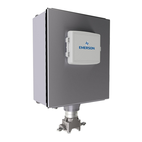
(SP), differential pressure (DP), and temperature (T), and linear meters measuring pulse or analog inputs, SP, and T. This manual describes how to install and configure the Emerson FB2200 flow computer hardware. For information on using the FBxConnect™ configuration software, see the online help that accompanies FBxConnect. - Page 6 Emerson FB2200 Flow Computer Instruction Manual D301784X012 March 2019 Figure 1-1. FB2200 Flow Computer HMI module Front cover Data plate Enclosure Sensor module Introduction...
-
Page 7: Safety Labels
SAFETY FIRST General instructions and safety reminders. Features The FB2200 flow computer includes the following key features: ▪ Enclosure suitable for use in Class I Division 2 non-incendive and Ex nA Zone 2 non- sparking environments. Enclosure available in either aluminum or compression-molded fiberglass ▪... -
Page 8: Fb2200 Flow Computer Models
U.S., metric, or other natural gas standard units FB2200 Flow Computer Models You can purchase two basic models of the FB2200 flow computer. In addition, each model is available in either an aluminum enclosure or a compression-molded fiberglass enclosure. -
Page 9: Fb2200 Flow Computer - No Integral Sensor
I/O channels. Figure 1-3. FB2200 Flow Computer – No Integral Sensor Version Central Processing Unit (CPU) The flow computer’s CPU is a NXP ®... - Page 10 Emerson FB2200 Flow Computer Instruction Manual D301784X012 March 2019 Base I/O consists of: Pressure (P) input from the MV sensor, differential pressure (DP) input from the MV sensor, ▪ connections for temperature (T) input from a customer-supplied RTD/PRT -or – a single Static Pressure Sensor with RTD/PRT connections.
-
Page 11: Power Options
Important Use only batteries supplied with the flow computer or sold by Emerson Remote Automation Solutions as spare parts for this flow computer. If you substitute a battery you obtain elsewhere you will void your certification unless it is the identical part from the same manufacturer as that supplied with the flow computer from Emerson. -
Page 12: Human-Machine Interface (Hmi) Module
Emerson FB2200 Flow Computer Instruction Manual D301784X012 March 2019 Human-Machine Interface (HMI) Module The flow computer includes an HMI module with an optional liquid crystal display (LCD) for local operator access to the device. The LCD, if present, presents a series of menus that sequentially displays the current values of particular process variables. -
Page 13: Fbxwifi™ Communications
Emerson FB2200 Flow Computer Instruction Manual D301784X012 March 2019 FBxWifi™ Communications ® The flow computer has an optional Wi-Fi transceiver that enables you to connect via a laptop or tablet from a distance. The distance supported varies depending on the laptop/tablet type and environmental conditions but is typically 70 to 100 feet from the front of the flow computer and 40 to 60 feet from the side and rear of the flow computer. - Page 14 Emerson FB2200 Flow Computer Instruction Manual D301784X012 March 2019 Figure 1-6. Possible Padlock Locations Location where customer-supplied padlocks can be used to lock the door Holes in the door latches of the fiberglass enclosure allow you to attach a wire seal.
- Page 15 Emerson FB2200 Flow Computer Instruction Manual D301784X012 March 2019 Figure 1-8. Potential Locations for Tamper-evident Tape Rotation Set Screws (2) – One shown Coupling Screws (4) – Two shown Introduction...
- Page 16 Emerson FB2200 Flow Computer Instruction Manual D301784X012 March 2019 Introduction...
-
Page 17: Section 2: Installation
The flow computer ships from the factory fully assembled, except for the optional solar panel assembly. Hazardous Locations For North America the FB2200 has certifications for Class I Division 2 (Groups A, B, C, & D) non- incendive, and non-hazardous locations only. Appendix A contains special information for Class I Division 2 installations. -
Page 18: Required Tools
Emerson FB2200 Flow Computer Instruction Manual D301784X012 March 2019 Table 2-1. Environmental Specifications Range Specification Configuration Aluminum Enclosure Fiberglass Enclosure Ambient No battery, C1D2 –40 °C to +80 °C – 35 °C to 80 °C Temperature (-40 °F to +176 °F) –... -
Page 19: Site Considerations
Emerson FB2200 Flow Computer Instruction Manual D301784X012 March 2019 Site Considerations The flow computer must reside in an accessible location for configuration and service. Refer to the dimensional drawings for information on the space required. ▪ Ensure the installation location provides easy access to the HMI module. - Page 20 Emerson FB2200 Flow Computer Instruction Manual D301784X012 March 2019 Figure 2-2. Dimensions – Multivariable Sensor Version - Aluminum Enclosure Installation...
- Page 21 Emerson FB2200 Flow Computer Instruction Manual D301784X012 March 2019 Figure 2-3. Dimensions – No Integral Sensor Version – Fiberglass Enclosure Installation...
- Page 22 Emerson FB2200 Flow Computer Instruction Manual D301784X012 March 2019 Figure 2-4. Dimensions – No Integral Sensor Version – Aluminum Enclosure Installation...
- Page 23 Emerson FB2200 Flow Computer Instruction Manual D301784X012 March 2019 Figure 2-5. Dimensions – Static Pressure Sensor Version – Fiberglass Enclosure Installation...
-
Page 24: General Wiring Guidelines
Emerson FB2200 Flow Computer Instruction Manual D301784X012 March 2019 Figure 2-6. Dimensions – Static Pressure Sensor Version – Aluminum Enclosure General Wiring Guidelines The flow computer’s pluggable terminal blocks use compression-type terminals that accommodate wire between 28 and 12 AWG. -
Page 25: Grounding
Emerson FB2200 Flow Computer Instruction Manual D301784X012 March 2019 Grounding The flow computer includes a ground stud on the bottom of the battery compartment Figure 2-7. Ground Stud Once you have installed the unit, run a ground wire between the ground stud on the ▪... -
Page 26: Mounting The Enclosure
Only use bolts supplied with the flow computer or sold by Emerson Remote Automation Solutions as spare parts. Refer to the figure for common flow computer assemblies with the bolt length required for proper flow computer installation. - Page 27 March 2019 Note For all other manifolds, contact your local Emerson Sales office or Emerson Impact Partner. Bolts are typically carbon steel or stainless steel. Confirm the material by viewing the markings on the head of the bolt and referencing the figure. If bolt material is not shown in the figure, contact your local Emerson Remote Automation Solutions representative for more information.
- Page 28 Emerson FB2200 Flow Computer Instruction Manual D301784X012 March 2019 Use the following bolt installation procedure: Carbon steel bolts do not require lubrication. Stainless steel bolts are factory-coated with a lubricant to ease installation. Do not apply any additional lubricant when installing either type of bolt.
-
Page 29: O-Rings With Flange Adapters
Emerson FB2200 Flow Computer Instruction Manual D301784X012 March 2019 O-rings with Flange Adapters DANGER Failure to install proper flange adapter O-rings may cause process leaks, which can result in death or serious injury. Only use the O-ring that is designed for its specific flange adapter. -
Page 30: Pole Mounting - Fiberglass Enclosure
Emerson FB2200 Flow Computer Instruction Manual D301784X012 March 2019 Figure 2-15. Aluminum Enclosure Pole Mounting 5/16-18 keps stainless steel hex nut 5/16-18 x 1.0 LG wire-lockable socket head cap screw Pole mounting bracket 2-inch diameter 5/16-18 x 4.0LG U-bolt Pole Mounting – Fiberglass Enclosure... - Page 31 Emerson FB2200 Flow Computer Instruction Manual D301784X012 March 2019 Figure 2-16. Fiberglass Enclosure Pole Mounting ¼ inch screw split lock stainless steel washer ¼-10 x .75LG thread forming torx head screw 5/16-18 keps stainless steel hex nut Pole mounting bracket 2 inch diameter 5/16-18 x 4.0LG U-bolt...
-
Page 32: Panel/Wall Mounting Dimensions - Aluminum Enclosure
Emerson FB2200 Flow Computer Instruction Manual D301784X012 March 2019 Panel/Wall Mounting Dimensions – Aluminum Enclosure Figure 2-17. Aluminum Enclosure Panel/Wall Mounting Mounting holes are 7.92 mm (0.312 in) diameter Installation... -
Page 33: Panel/Wall Mounting Dimensions - Fiberglass Enclosure
Emerson FB2200 Flow Computer Instruction Manual D301784X012 March 2019 Panel/Wall Mounting Dimensions – Fiberglass Enclosure Prior to mounting, attach mounting tabs to enclosure: Figure 2-18. Attaching mounting tabs Installation... - Page 34 Emerson FB2200 Flow Computer Instruction Manual D301784X012 March 2019 Figure 2-19. Fiberglass Enclosure Panel/Wall Mounting Mounting holes are 7.9 mm (0.31 in) wide Installation...
-
Page 35: Rotating The Housing
Re-tighten the two housing rotation set screws. Torque to 6 in-lbs. (0.7 N m). Power Modes To keep power consumption to a minimum, especially for remote sites, the FB2200 can run in two different power modes – Low Power Mode (4 MHz or 8 CPU MHz clock speed) or Standard Power Mode (60 MHz CPU clock speed). -
Page 36: Low Power Mode
March 2019 Low Power Mode The FB2200 normally runs in low power mode for typical metering applications. The radio Power Control function (configurable in FBxConnect) switches the flow computer into standard power mode at specific times when serial communications are required, then it reverts to low power mode when the communication period is over. -
Page 37: Standard Power Mode
4, the flow computer cannot operate in low power mode and automatically runs in standard power mode. Standard Power Mode When serial communication is active (other than to a remote 4088B MVT) the FB2200 operates in standard power mode. The unit also uses standard power mode when: The HMI module display is ON ▪... -
Page 38: Notes On Battery Life
Emerson FB2200 Flow Computer Instruction Manual D301784X012 March 2019 Table 2-5. Typical Power Usage – Standard Power Mode at room temperature Power Usage Power Usage Description (mW) at 12Vdc (mW) at 24Vdc Base flow computer with integral multivariable DP and... -
Page 39: Connecting Power
Emerson FB2200 Flow Computer Instruction Manual D301784X012 March 2019 Limit communication activity. ▪ Disable power to all I/O (except for the MV or static pressure sensor, or RTD). To do this, click ▪ Configure > I/O Setup > I/O Configuration > Properties and select Disable for each I/O module. -
Page 40: Connecting Battery Power
Emerson FB2200 Flow Computer Instruction Manual D301784X012 March 2019 Figure 2-22. DC Power Connections To external DC power supply Connecting Battery Power DANGER EXPLOSION HAZARD: Never remove end cap(s) in a hazardous location. Removing end cap(s) in a hazardous location could result in an explosion. - Page 41 Emerson FB2200 Flow Computer Instruction Manual D301784X012 March 2019 Figure 2-23. Removing Plastic Tabs from Battery Pack Open the enclosure. Installation...
- Page 42 Emerson FB2200 Flow Computer Instruction Manual D301784X012 March 2019 Loosen the two captive fastening screws at the top of the of the battery compartment, while holding onto the battery compartment door. Carefully rotate the electronics assembly towards you to reveal the inside of the battery compartment. A strap prevents the front of the compartment from rotating too far forward.
- Page 43 Emerson FB2200 Flow Computer Instruction Manual D301784X012 March 2019 Figure 2-25. Rotate Assembly Forward The battery cable inside the battery compartment is divided into two branches, each with its own pair of connectors. Take either pair of connectors and connect them to the battery; the red (positive) wire connector attaches to the red connection point on the battery and the black (negative) wire connector attaches to the black connection point on the battery.
- Page 44 Emerson FB2200 Flow Computer Instruction Manual D301784X012 March 2019 Figure 2-26. Connect the Battery Now you must secure the battery in the battery compartment so that it doesn’t move around. How you do this depends on which battery compartment configuration you have. If the battery compartment includes a strap for holding the battery, see Section 2.10.2.1 –...
- Page 45 Emerson FB2200 Flow Computer Instruction Manual D301784X012 March 2019 2.10.2.2 Securing the Battery with a Strap This type of battery compartment allows for certain accessories to be installed such as a relay or internal solar regulator. If you have an internal solar regulator installed in the battery compartment, you must remove its termination cover in order to fit the battery inside.
- Page 46 Emerson FB2200 Flow Computer Instruction Manual D301784X012 March 2019 Figure 2-29. Easing Battery Pack into Compartment Carefully push the battery under the solar regulator (if present) and against the back of the compartment, now strap it in tightly by pulling the ends of the strap.
- Page 47 Emerson FB2200 Flow Computer Instruction Manual D301784X012 March 2019 Figure 2-31. Battery Pack Attached to Compartment Route the extra portion of the strap as well as the wires of the free portion of the battery cable so that they sit in an open area of the battery compartment.
- Page 48 Emerson FB2200 Flow Computer Instruction Manual D301784X012 March 2019 Figure 2-32. Battery Pack Attached to Compartment Route the wires of the free portion of the battery cable so that they sit completely inside the open area at the top of the battery compartment.
-
Page 49: Connecting Solar Power
BATT– terminals and standard copper wire (#18 AWG minimum). Important Only use batteries supplied with the flow computer or sold by Emerson as spare parts for this ▪ flow computer. If you substitute a battery you obtain elsewhere you will void your certification unless it is the identical part from the same manufacturer as that supplied with the flow computer from Emerson. - Page 50 Emerson FB2200 Flow Computer Instruction Manual D301784X012 March 2019 Table 2-6. Solar Panel Electrical Characteristics Characteristic Value/Range 30W ± 10% Voltage (@peak power) 17.9V Current (@peak power) 1.68A Open Circuit Voltage 22.1V Short Circuit Current 1.74A Table 2-7. Solar Regulator Electrical Characteristics...
- Page 51 Emerson FB2200 Flow Computer Instruction Manual D301784X012 March 2019 Figure 2-33. Solar Controller Solar controller Fork connectors Remove the fork connectors and trim back the insulation on the wires ¼ inch. Figure 2-34. Removing Fork Connectors Remove the junction box cover. Use a utility knife to remove the knock-outs (Item 2) in the junction box (Item 1) and feed the wires from the solar controller into the junction box, and through the solar controller lock nut (Item 3).
- Page 52 Emerson FB2200 Flow Computer Instruction Manual D301784X012 March 2019 Use the solar controller lock nut to attach the solar controller to the junction box and use a 7/32” flat head screwdriver to attach the wires from the controller to the junction box connectors as shown.
- Page 53 Emerson FB2200 Flow Computer Instruction Manual D301784X012 March 2019 Figure 2-38. Wiring Solar Power – External Regulator Fast acting 6.3A one time fuse Conduit Battery If you ordered the flow computer with an internal solar regulator for the 30W solar panel, wire it...
- Page 54 Emerson FB2200 Flow Computer Instruction Manual D301784X012 March 2019 Figure 2-39. Wiring Solar Power – Internal Regulator Solar Panel Conduit Fast acting 6.3A one time fuse Solar Regulator Solar Battery Load Battery Installation...
-
Page 55: Installing The Optional 30W Solar Panel
Emerson FB2200 Flow Computer Instruction Manual D301784X012 March 2019 2.11 Installing the Optional 30W Solar Panel If you purchased the lead acid battery/30W solar panel kit for main power, you need to install the supplied solar panel. Refer to Figure 2-40 during this procedure. - Page 56 Emerson FB2200 Flow Computer Instruction Manual D301784X012 March 2019 Figure 2-40. Installing 30W Solar Panel 30W solar panel Adjustable angle bracket Pole mounting bracket U-bolt assembly (2) ¼ x 20 x .75LG Hex head cap screw (2) ¼ flat washer (2) ¼...
-
Page 57: Adjusting The Optional Solar Panel
Emerson FB2200 Flow Computer Instruction Manual D301784X012 March 2019 Figure 2-41. 30W Solar Panel Installed 2.12 Adjusting the Optional Solar Panel DANGER EXPLOSION HAZARD: Never remove end cap(s) in a hazardous location. Removing end cap(s) in a hazardous location could result in an explosion. - Page 58 Emerson FB2200 Flow Computer Instruction Manual D301784X012 March 2019 the site, on average, would receive one hour of solar energy at the panel's rated power level (1000W/m per day). This rating varies from less than one hour in northern Canada to more than six hours in the Sahara Desert.
-
Page 59: Connecting Communication Ports
Emerson FB2200 Flow Computer Instruction Manual D301784X012 March 2019 The mounting brackets allow you to adjust the solar panel for maximum solar exposure. 2.13 Connecting Communication Ports DANGER EXPLOSION HAZARD: Never remove end cap(s) in a hazardous location. Removing end cap(s) in a hazardous location could result in an explosion. - Page 60 Emerson FB2200 Flow Computer Instruction Manual D301784X012 March 2019 When connecting COM1 to another device using RS-422, use a cable with configurations as shown Figure 2-44: Figure 2-44. Connecting a Device to COM1 Using RS-422 RS-422 Port on other device...
-
Page 61: Connecting To Com2 And Com3
Emerson FB2200 Flow Computer Instruction Manual D301784X012 March 2019 Figure 2-45. Connecting a Device to COM1 Using RS-485 RS-422 Port on other device Regardless of the interface standard (RS-232, RS-422, or RS-485) you must use FBxConnect to configure the port for proper usage. - Page 62 Emerson FB2200 Flow Computer Instruction Manual D301784X012 March 2019 Figure 2-46. Connecting a Device to COM2 or COM3 Using RS-232 RS-232 Port on other device When connecting COM2 or COM3 to an RS-485 port on another device (for example, a...
- Page 63 Emerson FB2200 Flow Computer Instruction Manual D301784X012 March 2019 Figure 2-47. Connecting a Device to COM2 or COM3 Using RS-485 RS-485 Port on other device Regardless of the interface standard (RS-232 or RS-485), you must use FBxConnect to configure the port for proper usage.
-
Page 64: Connecting To Ethernet
Emerson FB2200 Flow Computer Instruction Manual D301784X012 March 2019 Connecting to Ethernet The Ethernet port is a standard 8-pin 10/100 Base T RJ-45 modular connector located on the bottom right side of the CPU enclosure. Figure 2-48. Connecting to Ethernet Ethernet Port Connect to an Ethernet switch using the appropriate Category 5 shielded patch cable. -
Page 65: Security Intrusion Switch
Emerson FB2200 Flow Computer Instruction Manual D301784X012 March 2019 Figure 2-49. Ethernet port jumper 2.14 Security Intrusion Switch If ordered from the factory, the door contact wires to a momentary switch as shown using cable part number 399331-01-0. Installation... - Page 66 Emerson FB2200 Flow Computer Instruction Manual D301784X012 March 2019 Figure 2-50. Wiring the Door Contact Terminal to a Momentary Switch If you order the optional security intrusion switch, the flow computer ships from the factory with the door switch option enabled. To verify this, you can run FBxConnect software and select Services >...
-
Page 67: Section 3: I/O Configuration And Wiring
Wiring a Digital Output to the Optional Relay ▪ Radio Wiring I/O in the FB2200 flow computer comes from the integrated multivariable sensor and RTD connector, the CPU board, as well as the optional mixed I/O modules. Note When using a digital output to drive an inductive load (such as a relay coil), place a suppression diode across the load. - Page 68 Emerson FB2200 Flow Computer Instruction Manual D301784X012 March 2019 Figure 3-1. Base I/O (AI/AO 1 & 2, DI/DO/PI 1 & When wiring a 1-5 V Analog Input (AI), use configuration at left When wiring a 4-20 mA Analog Input (AI), use configuration at left...
-
Page 69: Analog Inputs
High Side Switch Analog Inputs The FB2200 flow computer includes two on-board channels you can individually configure as either analog inputs (AI) or analog outputs (AO). The optional 8-channel expansion I/O module includes 4 additional channels you can individually configure as AIs or AOs. In addition, if you purchased the optional 6-channel expansion I/O module, there are two additional channels you can individually configure as either AIs or AOs. - Page 70 Emerson FB2200 Flow Computer Instruction Manual D301784X012 March 2019 Note No external resistor is required for a current (mA) device. You can apply a 250 ohm resistor using analog input configuration selections in FBxConnect. When configured as analog inputs, the channels have the following characteristics: Table 3-1.
-
Page 71: Ai Wiring
Emerson FB2200 Flow Computer Instruction Manual D301784X012 March 2019 3.1.1 AI Wiring The following diagrams show how to wire the analog input. Figure 3-3. AI Wiring: Base I/O (AI/AO1 & AI/AO2 only) When wiring a 1-5 V Analog Input (AI), use configuration at left... -
Page 72: Analog Outputs
Field Device Analog Outputs The FB2200 flow computer includes two on-board channels you can individually configure as either analog outputs (AO) or analog inputs (AI). The optional 8-channel expansion I/O module includes 4 additional channels you can individually configure as AOs or AIs. In addition, if you purchased the optional 6-channel expansion I/O module, there are two additional channels you can individually configure as either AOs or AIs. -
Page 73: Ao Wiring
Emerson FB2200 Flow Computer Instruction Manual D301784X012 March 2019 AI/AO6). If module is present you can ▪ You can configure a fail state so that configure any (or none) of the four on power up or if the CPU fails the channels as AOs. -
Page 74: Digital Inputs
Field Device Digital Inputs Depending upon how you ordered it, the FB2200 flow computer includes two, six, or ten channels you can individually configure as digital inputs (DI), digital outputs (DO), or pulse inputs (PI). When configured as digital inputs, the channels have the following characteristics: Table 3-3. -
Page 75: Di Wiring
Emerson FB2200 Flow Computer Instruction Manual D301784X012 March 2019 ▪ 1 to 4 additional isolated channels on ▪ When you configure a channel as a DI it optional 6-channel expansion I/O cannot be used as a DO or PI channel module (ISO DI/DO/PI7 to ISO DI/DO/PI10). -
Page 76: Digital Outputs
D301784X012 March 2019 Digital Outputs Depending upon how you ordered it, the FB2200 flow computer includes two, six, or ten channels you can configure as digital outputs (DO), digital inputs (DI) or pulse inputs (PI). Note When using a digital output to drive an inductive load (such as a relay coil), place a suppression diode across the load. -
Page 77: Do Wiring
Emerson FB2200 Flow Computer Instruction Manual D301784X012 March 2019 3.4.1 DO Wiring The following diagrams show how to wire the digital output. Figure 3-9. DO Wiring: Base I/O (DI/DO/PI1 & DI/DO/PI2) Power Supply 30Vdc Max 500 mA load max I/O Configuration and Wiring... - Page 78 Emerson FB2200 Flow Computer Instruction Manual D301784X012 March 2019 Figure 3-10. DO Wiring: Optional 8-channel Expansion I/O Module (ISO DI/DO/PI3,4,5,6) and Optional 6-channel Expansion I/O Module (ISO DI/DO/PI7,8,9,10) 500 mA load max Power Supply 30Vdc Max Low Side Switch High Side Switch...
-
Page 79: Pulse Inputs
March 2019 Pulse Inputs Depending upon how you ordered it, the FB2200 flow computer includes two, six, or ten channels you can individually configure as either pulse inputs (PI), digital inputs (DI), or digital outputs (DO). When configured as pulse inputs, the PI channels have the following characteristics: Table 3-5. -
Page 80: Pi Wiring
Emerson FB2200 Flow Computer Instruction Manual D301784X012 March 2019 3.5.1 PI Wiring The following diagrams show how to wire the pulse inputs. Figure 3-11. PI Wiring: Base I/O (DI/DO/PI1 & DI/DO/PI2) Open Drain Type or Open Collector Device (Externally Powered) Figure 3-12. - Page 81 Emerson FB2200 Flow Computer Instruction Manual D301784X012 March 2019 RTD connections reside on the terminal blocks inside the enclosure. The flow computer supports 2- wire, 3-wire, and 4-wire operation. Route the RTD cable through the conduit fittings and connect them on the terminal blocks (as shown on Figure 3-13, Figure 3-14 and Figure 3-15).
-
Page 82: Connecting A Rosemount 4088B In A Second Meter Run
Emerson FB2200 Flow Computer Instruction Manual D301784X012 March 2019 Figure 3-15. RTD/PRT Wiring for 4-Wire 4-Wire RTD Connecting a Rosemount 4088B in a Second Meter The flow computer supports two optional electro-mechanical relays for switching on/off external circuits or devices. If you order this option, the relays ship from the factory mounted to the top of the battery compartment inside the flow computer enclosure. - Page 83 Emerson FB2200 Flow Computer Instruction Manual D301784X012 March 2019 Figure 3-16. Connecting a 4088B Transmitter for a Second Meter Run Enable termination in software RS-485 bus, twisted pair required Enable AC termination using switches. User-provided power supply (5.4V to 30V) Set switches on the 4088B for bus termination or use a 120-ohm resistor.
-
Page 84: Wiring A Digital Output To The Optional Relay
Emerson FB2200 Flow Computer Instruction Manual D301784X012 March 2019 Wiring a Digital Output to the Optional Relay The flow computer supports two optional electro-mechanical relays for switching on/off external circuits or devices. If you order this option, the relays ship from the factory mounted to the top of the battery compartment inside the flow computer enclosure. -
Page 85: Radio Wiring
Emerson FB2200 Flow Computer Instruction Manual D301784X012 March 2019 Figure 3-18. Relay Wired to Non-Isolated DO To customer load Power Supply 24Vdc Radio Wiring To power a radio, you wire it to the RADIO PWR and RADIO RTN terminals. These follow whatever the power supply provides the flow computer at the DCIN+ terminal. - Page 86 Emerson FB2200 Flow Computer Instruction Manual D301784X012 March 2019 I/O Configuration and Wiring...
-
Page 87: Section 4: Operation
Emerson FB2200 Flow Computer Instruction Manual D301784X012 March 2019 Section 4: Operation This section covers the following topics: ▪ Powering Up/Powering Down the Device ▪ Establishing Communications ▪ Communicating using the HMI Module This section describes day-to-day operation of the flow computer including how to turn it on and off and how to communicate with it. -
Page 88: Communicating With A Laptop Using One Of The Serial Ports
BSAP. See these documents for more information: DNP3 Protocol Specifications Manual (for FB1000 and FB2000) (D301806X012) ▪ ▪ ROC Protocol Specifications Manual (for Emerson FB Series Flow Computers) (D301828X012) ▪ FBxConnect Configuration Software User Manual (D301850X012) BSAP Communication Guide for FB1000/FB2000 Series Flow Computers (D301808X012) ▪... -
Page 89: Communicating With A Laptop Using Ethernet
Emerson FB2200 Flow Computer Instruction Manual D301784X012 March 2019 4.2.3 Communicating with a Laptop Using Ethernet Your laptop must have Field Tools software with FBxConnect software installed. Additionally, you must know a valid username/password combination for the flow computer. : DANGER EXPLOSION HAZARD: Ensure the area in which you perform this operation is non-hazardous. -
Page 90: Communicating Using The Hmi Module
Emerson FB2200 Flow Computer Instruction Manual D301784X012 March 2019 Click Connect to start the FBxConnect software. Log into the flow computer if prompted. Use the FBxConnect software to view or change any desired parameters. When finished, log off the flow computer and disconnect from the wireless network. - Page 91 Emerson FB2200 Flow Computer Instruction Manual D301784X012 March 2019 Figure 4-2. Infrared (IR) Button Location Left Infrared (IR) Button Down Infrared (IR) Button Up Infrared (IR) Button Right Infrared (IR) Button Note When using the IR buttons, aim your finger at the round spot just below the arrow.
- Page 92 Emerson FB2200 Flow Computer Instruction Manual D301784X012 March 2019 Option Usage LEFT button Idle Mode (Screen is off) Hold to Wake up the display. ▪ Screen Saver Mode Log out (if logged in) ▪ Data Entry Mode Tap once to move the cursor LEFT. Hold to perform action shown ▪...
-
Page 93: Section 5: Service And Troubleshooting
Emerson-authorized repair facility. Important Use only batteries supplied with the flow computer or sold by Emerson Remote Automation Solutions as spare parts for this flow computer. If you substitute a battery you obtain elsewhere you will void your certification unless it is the identical part from the same manufacturer as that supplied with the flow computer from Emerson. -
Page 94: Returning The Unit For Repairs
Other types of repairs cannot be performed in the field. In those cases, you must ship the unit to an Emerson-authorized repair facility. Contact Emerson Remote Automation Solutions for a return authorization number and instructions for where to ship the unit. -
Page 95: Interpreting The Status Leds
Emerson FB2200 Flow Computer Instruction Manual D301784X012 March 2019 WARNING International safety regulations restrict the shipment of lithium batteries. If you need to return the flow computer, remove the lithium battery before you ship the unit. Failure to remove the lithium battery may delay or prevent shipment of the flow computer. - Page 96 Emerson FB2200 Flow Computer Instruction Manual D301784X012 March 2019 Table 5-1. LED Descriptions Color/State Meaning Link LED GREEN An active wired Ethernet connection exists. Otherwise it is off. (FB1200/FB2200 only) Input LED GREEN One of the IR buttons is being pressed.
-
Page 97: Switch And Buttons
Emerson FB2200 Flow Computer Instruction Manual D301784X012 March 2019 Switch and Buttons A momentary switch and two push buttons on the HMI module provide troubleshooting options for the flow computer. Figure 5-3. Switch and Buttons DANGER EXPLOSION HAZARD: Never open the enclosure in a hazardous location. Opening the enclosure in a hazardous location could result in an explosion. -
Page 98: Removing/Replacing The Hmi Module
Emerson FB2200 Flow Computer Instruction Manual D301784X012 March 2019 Button Name Purpose Procedure Currently undefined None Removing/Replacing the HMI Module You do not need to power down the unit to remove/replace the HMI module. DANGER Ensure the flow computer is in a non-hazardous area. Never remove/replace the HMI module in a hazardous area. -
Page 99: Replacing The Main Battery Pack
Emerson FB2200 Flow Computer Instruction Manual D301784X012 March 2019 Close the enclosure. Replacing the Main Battery Pack Periodically you must replace the main battery pack. Figure 5-5. Main Battery Pack The device provides a battery cable with two pairs of battery connectors, enabling you to hot-swap the battery pack in a non-hazardous location. - Page 100 Emerson FB2200 Flow Computer Instruction Manual D301784X012 March 2019 DANGER EXPLOSION HAZARD: Do not disconnect equipment unless power has been removed or the area is known to be non-hazardous. DANGER EXPLOSION HAZARD: Substitution of any components may impair suitability for Class I, Division...
- Page 101 Emerson FB2200 Flow Computer Instruction Manual D301784X012 March 2019 Loosen the two captive fastening screws at the top of the of the battery compartment and hold the battery compartment door as you carefully rotate the electronics assembly towards you to reveal the inside of the battery compartment. A strap prevents the front of the compartment from rotating too far forward.
- Page 102 Emerson FB2200 Flow Computer Instruction Manual D301784X012 March 2019 Figure 5-8. Pry Out the Old Battery Pack – Leave Connected to Cable If you have an internal solar regulator installed in the battery compartment, you must remove the termination cover. Remove the two screws (left and right) that fasten the termination cover to the solar regulator, and then set the termination cover aside.
- Page 103 Emerson FB2200 Flow Computer Instruction Manual D301784X012 March 2019 Figure 5-9. Remove the Termination Cover (if present) A strap with a hook and loop fastener holds the battery in place. Unstrap the battery but leave the connectors on the current battery connected. Gently lift the battery with the battery cable attached out of the compartment.
- Page 104 Emerson FB2200 Flow Computer Instruction Manual D301784X012 March 2019 Figure 5-11. Old Battery (left) and New Battery (right) Sit on Enclosure The battery cable is divided into two branches, each with its own pair of connectors. Take the free pair of connectors and connect them to the new battery; the red (positive) wire connector attaches to the red connection point on the new battery and the black (negative) wire connector attaches to the black connection point on the new battery.
- Page 105 Emerson FB2200 Flow Computer Instruction Manual D301784X012 March 2019 Now disconnect the old battery from its connectors and set the old battery aside (be sure to dispose of it safely according to local regulations). Figure 5-13. Old Battery Disconnected (left), New Battery Remains Connected...
- Page 106 Emerson FB2200 Flow Computer Instruction Manual D301784X012 March 2019 Figure 5-14. Thread the Battery Strap Pick up the new battery and carefully ease it into the battery compartment with the writing on the battery facing out and the connectors on the upper right-hand side. Nothing (including the strap) can be behind the battery.
- Page 107 Emerson FB2200 Flow Computer Instruction Manual D301784X012 March 2019 Figure 5-16. Tighten the Battery Strap The strap includes a narrow opening into which you can slide the other end of the strap to help you tighten it. Figure 5-17. Opening in the Battery Strap Route the extra portion of the strap as well as the wires of the free portion of the battery cable so that they sit in an open area of the battery compartment.
-
Page 108: Removing/Replacing The Sram Battery
Emerson FB2200 Flow Computer Instruction Manual D301784X012 March 2019 Removing/Replacing the SRAM Battery A lithium coin cell battery provides backup power for the SRAM and the real time clock. The SRAM backup battery can last for up to 10,000 hours of cumulative operation, and only runs if the main power system fails. - Page 109 Emerson FB2200 Flow Computer Instruction Manual D301784X012 March 2019 Figure 5-18. Loosen Captive Fastening Screws Figure 5-19. Remove the CPU Enclosure Cover Grasp the coin cell battery and with your fingernail in the groove of the top of the battery, slide it out of its slot.
-
Page 110: Upgrading System Firmware
Reattach the cover of the CPU enclosure. Close the enclosure. Upgrading System Firmware Periodically Emerson releases new system firmware for the flow computer to introduce new features or update system functions. You must know a valid username/password combination for the flow computer to complete this process. - Page 111 Emerson FB2200 Flow Computer Instruction Manual D301784X012 March 2019 Launch Field Tools and use FBxConnect to connect to the flow computer. Select the Services tab, then click Firmware Update. Click Configuration Save to save the flow computer’s configuration. Click History Collection to save the historical data contained in the flow computer.
- Page 112 Emerson FB2200 Flow Computer Instruction Manual D301784X012 March 2019 Service and Troubleshooting...
-
Page 113: Appendix A: Special Instructions For Class I Division 2 Locations
An RTD may be supplied with the Emerson FB2200 flow computer. Connection to the RTD is approved as a non-incendive circuit so that Division 2 wiring methods are not required. - Page 114 Emerson FB2200 Flow Computer Instruction Manual D301784X012 March 2019 Figure A-1. Data Plate (Fiberglass Enclosure, No Battery) - Class I Division 2 Non-incendive (UL) Figure A-2. Data Plate (Fiberglass Enclosure, Lead Acid Battery) - Class I Division 2 Non-incendive (UL),...
- Page 115 Emerson FB2200 Flow Computer Instruction Manual D301784X012 March 2019 Figure A-3. Data Plate (Fiberglass Enclosure, No Battery, Relay) - Class I Division 2 Non-incendive (UL) Figure A-4. Data Plate (Aluminum Enclosure, No Battery) - Class I Division 2 Non-incendive (UL)
- Page 116 Emerson FB2200 Flow Computer Instruction Manual D301784X012 March 2019 Figure A-5. Data Plate (Aluminum Enclosure, Lead Acid Battery) - Class I Division 2 Non-incendive (UL) Figure A-6. Data Plate (Aluminum Enclosure, No Battery, Relay) - Class I Division 2 Non-incendive (UL)
-
Page 117: Appendix B: Atex Non-Sparking Zone 2 Certifications
For Zone 2 installations, ensure that the flow computer is installed and used in such a way to ▪ prevent the danger of electrostatic charges. The FB2200 enclosure must require a tool to permit access. ▪ Refer to field replacement guides for replacement of the following parts: ▪... - Page 118 IEC 60079-15 4th Edition EN 60079-0 :2012+A11:2013 ▪ EN 60079-15:2010 ▪ Enclosure Rating: IP54 Terminal blocks for the FB2200 have the following characteristics: Terminal blocks can accommodate two conductors per channel. ▪ ▪ Stranded or solid wire allowed. Torque values: NM 0.5-0.6 ▪...
-
Page 119: Index
Emerson FB2200 Flow Computer Instruction Manual D301784X012 March 2019 Index Connecting Ethernet .............. 58 4088B transmitter ........... 76 I/O ............... 61 power ..............33 PRT ..............75 Analog Inputs ............63 RTD ..............75 Analog Outputs ............66 Run 2 transmitter ..........76 AO wiring .............. - Page 120 Emerson FB2200 Flow Computer Instruction Manual D301784X012 March 2019 1-7. Removing Fiberglas Enclose Cap and Latch ..10 2-37. Routing Battery Wires ......... 46 1-8. Potential Locations for Tamper-evident Tape . 11 2-38. Wiring Solar Power ........47 2-1. Dimensions – Multivariable Sensor Version - 2-39.
- Page 121 Emerson FB2200 Flow Computer Instruction Manual D301784X012 March 2019 4-2. Infrared (IR) Button Location ......85 5-1. FB2100 Flow Computer Components .... 88 Hazardous locations 5-2. LED Locations ..........89 ATEX Zone 2 ............111 5-3. Switch and Buttons ........91 Class I Division 2 ..........
- Page 122 Emerson FB2200 Flow Computer Instruction Manual D301784X012 March 2019 Power 1-1. Memory ............5 connecting ............33 1-2. FB2200 I/O Configurations ......6 low power mode ..........30 1-3. Power Options ..........7 modes ..............29 1-4. Serial Ports ............. 7 standard power mode ..........
- Page 123 Emerson FB2200 Flow Computer Instruction Manual D301784X012 March 2019 Index...
- Page 124 Emerson Automation Solutions Remote Automation Solutions Emerson FZE P.O. Box 17033 © 2018-2019 Remote Automation Solutions, a business unit of Emerson Automation Jebel Ali Free Zone – South 2 Solutions. All rights reserved. Dubai U.A.E. This publication is for informational purposes only. While every effort has been made to ensure...
Need help?
Do you have a question about the FB2200 and is the answer not in the manual?
Questions and answers