Table of Contents
Advertisement
Quick Links
Advertisement
Table of Contents

Related Manuals for Simplex 4006-9121


Summary of Contents for Simplex 4006-9121
- Page 1 Technical Manuals Online! - http://www.tech-man.com...
- Page 2 Tyco Safety Products. Tyco, Simplex, the Simplex logo, IDNet, SmartSync and WALKTEST are registered trademarks of Tyco International Ser- vices AG or its affiliates in the US and/or other countries.
- Page 3 FCC Information This equipment complies with Part 68 of the FCC rules and the requirements adopted by the ACTA. On the door of this equip- ment is a label that contains, among other information, the following product identifier: US:5QWAL01B4008. If requested, the number must be provided to the telephone company.
- Page 4 Computer DACT Network Service Unused Provider's RJ-11 Jack Facilities Telephone Line Telephone Network Demarcation Unused Telephone Point RJ-11 Jack Answering System Telephone Connectors for the DACT are terminal blocks on the DACT module. Refer to DACT Wiring in Chapter 2 of this manual for specific DACT wiring instructions.
-
Page 5: Cautions And Warnings
DO NOT INSTALL ANY PRODUCT THAT APPEARS DAMAGED. Upon unpacking your product, inspect the contents of the carton for shipping damage. If damage is apparent, immediately file a claim with the carrier and notify Simplex. ELECTRICAL HAZARD - Disconnect electrical field power when making any internal adjustments or repairs. Servicing should be performed by qualified Technical Representatives. - Page 6 Technical Manuals Online! - http://www.tech-man.com...
-
Page 7: Table Of Contents
Table of Contents Overview ....................1-1 Main System Board.......................... 1-1 Power supply ........................... 1-2 Environmental Specifications ........................1-2 Option Modules ............................1-2 4006-9801 Expansion Power Supply (EPS) ..................1-2 4006-9802 Expansion IDC Module (XIM) ..................1-2 4006-9805 and 4006-9806 City Circuit Cards.................. 1-2 4006-9803 Expansion Relay Module .................... - Page 8 General Wiring Notes ........................2-5 Location of Expansion Power Supply NACs (If Used) ..............2-5 NAC ratings ............................2-7 Auxiliary Relay Wiring ..........................2-8 DACT................................2-9 Remote Annunciator Wiring ........................2-11 City Connect Module Wiring........................2-12 Auxiliary 24 V Wiring ..........................2-13 Connecting to AC Power ........................2-14 Wiring Battery Power..........................2-15 Depleted Battery Cutout .........................2-16 Safety Ground/Ferrite Bead ........................2-16...
- Page 9 Setting Pulse Rate ..........................4-3 Setting Pulse Frequency........................4-4 Reporting Format ..........................4-4 AC Fail Delay ............................ 4-4 Test Report Time ..........................4-5 Programming Contact ID (CID) Points .....................4-5 Programming Event Codes ........................4-6 Saving Changes ............................4-6 Programming Annunciator LEDs ............5-1 Adding an Annunciator ..........................5-2 Automatically Adding Annunciator Cards..................
- Page 10 Control Functions .............................7-4 Setting the Time and Date........................7-5 Reports..............................7-5 Diagnostics...............................7-5 WalkTest ..............................7-6 Setting WalkTest Options ......................... 7-6 Advanced Operations..........................7-7 Upload/Download ..........................7-7 Restarting the CPU ........................... 7-7 Viewing Software Revision Number and Job Info................7-7 Appendix A. Battery Standby Calculations Current Draw for System Components ....................
- Page 11 Technical Manuals Online! - http://www.tech-man.com...
- Page 12 Technical Manuals Online! - http://www.tech-man.com...
-
Page 13: Overview
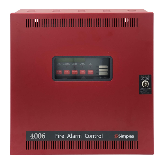
In This Chapter This publication describes how to install, configure, operate, program, and test an 4006-9101 and 4006-9121 (includes door-mounted annunci- ator) Fire Alarm Control Panel (FACP). In cases where the installation, Environmental Specifications ....1-2 wiring, or programming procedure is identical for both panels, the term Option Modules . -
Page 14: Power Supply
Chapter 1. Overview Power supply city circuit. The card is mounted to the right of the MSB at the top of the chassis. The 4006-9805 and 4006-9806 city • 120 VAC, 60 Hz, 4A; 240V, 50 Hz, 3A cards are identical except that the 4006-9805 provides hard- •... -
Page 15: Initiating Devices
Chapter 1. Overview adjunct panels for use with 4006 Fire Alarm Control Panels • Fixed temperature trip point: 135°F (FACPs). Rate of Rise trigger: 15°F-25°F per minute only at tempera- The base version of the NAC Extender is a single-board sys- tures of 90°F or greater tem consisting of four NACs, a power supply and charger, Detector Bases... - Page 16 Chapter 1. Overview Table 1-1 Operator Keys (Continued) Table 1-1 Operator Keys Function Function The Function Menu is displayed when the <Function> key is pressed at the Acknowledges any unacknowledged fire high-level status screen. Use the <Previ- ALARM alarms in the system, and scrolls FUNCTION ous>...
-
Page 17: Logging In And Out
Chapter 1. Overview Logging In and Out Access: Level 1 Passcode: Certain operator functions are passcode-protected at differ- Use the Keypad to enter the appropriate passcode. ent levels. This section describes the operator functions, their default access level, and the login/logout procedure. When the passcode is correct, press the <ENTER>... -
Page 18: Alarm Groups
Chapter 1. Overview Alarm Groups Alarm groups allow you to implement basic selective signal- ling applications. As you program input (zone of smoke detectors) and output points (NAC or relay), you are given the opportunity to associate the point with an alarm group number. -
Page 19: Installation And System Checkout
Chapter 2. Installation and System Checkout Back Box Mounting In This Chapter The back box can be surface-mounted or semi-flush mounted to the Back Box Mounting ....2-1 wall. -
Page 20: Guidelines For Locating Backbox
Chapter 2. Installation and System Checkout Semi-Flush Mounting • All Aux Relay loads must be powered from the AUX power circuit or from a regulated, 24 VDC, power-lim- Semi-flush mounting involves recessing the backbox into a ited power supply that is UL-listed for fire protective wall and attaching it directly to the wall's studs. -
Page 21: Idc Wiring
EOLR (Class B) or Class A • Conductors must test free of all grounds and stray volt- Board (Class A). For Simplex Model 4098-9683 relay base, limit is one device per circuit. For all other detec- ages before connection to appliances and panel. -
Page 22: Wiring 4098-9682 Four-Wire Base
Chapter 2. Installation and System Checkout Refer to smoke/heat Class A Wiring base installation instructions, 574- 706, for specific wir- ing details for bases and LED modules 733-893 3.3K EOLR OPTIONAL EXPANSION IDC (XIM) PROVIDES 5 ADDITIONAL IDCs. OPTIONAL CLASS A ADAPTER WIRING IS THE SAME AS FOR Class B Wiring IDCs ON MSB... -
Page 23: Nac Wiring
.22uF maximum is allowed. NACs • If wiring is routed outside the building, use of a listed Main secondary protector is required. Use Simplex 2081- System 9028 or 2081-9044. A protector must be installed at Board each building exit/entrance. Each 2081-9028 adds .2 ohms wiring resistance. - Page 24 Chapter 2. Installation and System Checkout TYPICAL AUDIBLE/VISIBLE APPLIANCES NAC - NAC - NAC - NAC+ NAC+ NAC+ TYPICAL AUDIBLE/VISIBLE APPLIANCES NAC - NAC+ 733-894 10K EOLR 9 10 MAIN SYSTEM BOARD - CONVENTIONAL (MSB - C) Figure 2-6 Main System Board NACs TYPICAL AUDIBLE/VISIBLE APPLIANCES NAC - NAC -...
-
Page 25: Nac Ratings
Synchronization of strobes across all NACs in a system is Multi-Candela Notification Appliances. UL Listed for the Simplex models noted in the table below. See the table below for maximum number allowed of each For all other UL Listed Notification Appliances, NACs are appliance per NAC. -
Page 26: Auxiliary Relay Wiring
Chapter 2. Installation and System Checkout Auxiliary Relay Wiring • Relay 1 is programmable. Its default operation is Com- mon Alarm - On Until Reset. Jumper is P1. • All wiring must be 18 AWG (minimum) to 12 AWG • Relay 2 is a normally energized, common trouble relay. -
Page 27: Dact
If wiring is routed outside the building, use of a listed • The DACT requires two telephone line connections to secondary protector is required. Use Simplex 2081- meet NFPA72 requirements. Wire from TB5-3/TB5-4 9028 or 2081-9044. A protector must be installed at and TB5-7/TB5-8 to an RJ-11 or other Telcom wiring each building exit/entrance. - Page 28 Chapter 2. Installation and System Checkout Table 2-3 Compatible DACRs Digital Alarm Communicator Receiver (DACR) Simplex Osborne/ SUR- SUR- Silent Silent 2, 3 ADEMCO Communication Central Hoffman Radionics GARD FBII GARD Knight Knight 1, 3 Format Station QuickAlert D6600 CP220FB...
-
Page 29: Remote Annunciator Wiring
• If wiring is routed outside the building, use of a listed limit is 4, 000 feet. secondary protector is required. Use Simplex 2081- Maximum wiring capacitance is 0.58µF total, 9028 or 2081-9044. A protector must be installed at wire-to-wire plus wire-to-shield. -
Page 30: City Connect Module Wiring
If wiring is routed outside the building, use of a listed configured. Circuits may be configured for reverse- secondary protector is required. Use Simplex 2081- polarity or local energy operation. See jumper setting 9028 or 2081-9044. A protector must be installed at table for details. -
Page 31: Auxiliary 24 V Wiring
Chapter 2. Installation and System Checkout Auxiliary 24 V Wiring • Compatible with Simplex 4098 Series Peripherals; 2098 Series Relay Modules; all Simplex 4090 Series IDNet • All wiring must be 18 AWG (minimum) to 12 AWG Peripherals; and 4610-9111 / 4606-9101 Annunciators. -
Page 32: Connecting To Ac Power
Chapter 2. Installation and System Checkout Connecting to AC Power terminals on the main system board. Wire Black to the left terminal of TB4. Wire White to the right terminal of • Before handling AC feed, use a voltmeter to verify the TB4. -
Page 33: Wiring Battery Power
Chapter 2. Installation and System Checkout Wiring Battery Power tom edge on the main system board. Insert the connec- tor left-justified, with the red wire to the left. • The main battery harness connects the main system • The EPS connects to the battery header next to the bat- board to the battery set in the same cabinet. -
Page 34: Depleted Battery Cutout
Chapter 2. Installation and System Checkout Depleted Battery Cutout System Powerup and Checkout For depleted battery cutout, remove the jumper shown in Use the following procedure to apply AC and battery power Figure 2-17 from the main system board. If you are using an to the 4006. -
Page 35: Replacing Lithium Battery
Chapter 2. Installation and System Checkout Test mode is activated by placing the magnet at the location Table 2-4 Testing Circuit Supervision indicated by the "I" mark, which is embossed on the detector housing. The visible LED flashes to indicate the detector's Condition Corresponding LEDs condition. - Page 36 Chapter 2. Installation and System Checkout age is required for full charge. Control of battery charge voltage relative to ambient temperature prolongs battery life. The chart below shows the proper range of battery voltage across the specified operating range of the equipment. The chart is for 12-cell battery sets, with nominal 24V rating.
-
Page 37: Programming Idcs, Nacs, And Aux Relays
Chapter 3. Programming IDCs, NACs, and AUX Relays NOTICE TO INSTALLERS, AUTHORITIES HAVING JURISDICTION, AND OTHER INVOLVED PARTIES This product incorporates field-programmable software. In order for the product to comply with the requirements in the Stan- dard for Control Units and Accessories for Fire Alarm Systems, UL 864, certain programming features or options must be limited to specific values or not used at all as indicated below. -
Page 38: Default General Alarm Programming
Chapter 3. Programming IDCs, NACs, and AUX Relays Keep the following in mind if you are adding or deleting an Press <ENTER>. The Programming menu appears. expansion IDC module. [Points] is the default selection, which allows you to make changes to a specific point’s programming. •... - Page 39 Chapter 3. Programming IDCs, NACs, and AUX Relays Table 3-1 IDC Function Types Use the <NEXT> and <PREV> keys to scroll through the choices until [Edit] is displayed. Function Device State = Status Description <ENTER>=Accept Type IDC: [Edit] Normal = NORMAL Current Limited = FIRE Press Enter.
-
Page 40: Entering Labels
Chapter 3. Programming IDCs, NACs, and AUX Relays Note: The alarm verification cycle works on a per-zone and allows editing. Clear Label deletes the existing label basis as follows. If a device with the function type first and then allows editing.) VSMOKE enters a current-limited state, the alarm verifica- IDC1 tion cycle begins. -
Page 41: Editing Alarm Groups
Chapter 3. Programming IDCs, NACs, and AUX Relays Table 3-2 Word Library (Continued) move between the alarm groups. Press <ENTER> when all the values are set correctly. Programming NACs upper Boiler_RM Restroom Use the following procedure to edit the programming of the lower Classroom Room... - Page 42 Chapter 3. Programming IDCs, NACs, and AUX Relays Table 3-3 NAC Function Types NAC1 [SSIG] TEMPRL Function Description Use the <NEXT> and <PREV> keys to select the Type appropriate Function. Use the right arrow key (>)to General Alarm (on steady-til-reset). Use for NAC move the cursor to the coding pattern, and then use the circuits containing visual-only devices.
-
Page 43: Editing Point Label
Chapter 3. Programming IDCs, NACs, and AUX Relays Editing Point Label Refer back to Table 3-2 for a list of words in the This option allows you to assign a 20-character custom label library. to each NAC point. Pressing <ENTER> saves the current label. Pressing Follow the steps in “Accessing Menus.”... -
Page 44: Programming Aux Relays
Chapter 3. Programming IDCs, NACs, and AUX Relays Programming AUX Relays Note: Refer to table located at top of Page 3-1 for UL 864 compliant options. Aux Relay programming allows you to define the following Table 3-5 Relay Function Types for the first auxiliary relay located on the MSB, and the expansion relays (if installed). -
Page 45: Editing Point Label
Chapter 3. Programming IDCs, NACs, and AUX Relays Note: Elevator recall requires the following: Use the left and right arrow keys to move to the next letter in the label. • The relay must have a function type of Primary or Alter- nate and must be wired to the appropriate elevator con- •... - Page 46 Technical Manuals Online! - http://www.tech-man.com...
-
Page 47: Programming The Dact
Chapter 4. Programming the DACT In This Chapter The panel’s DACT (Digital Alarm Communicator Transmitter) allows the panel to use one or two telephone lines to call a supervising station (remote station or central station) and report a local alarm, trouble, or Accessing DACT Menu . -
Page 48: Programming Dact Options
Chapter 4. Programming the DACT Use the <NEXT> and <PREV> keys to select one of the Opt: [Enable DACT] following choices. Press <ENTER>. The following appears. • Options. This choice allows you to program a wide range of DACT parameters (supervising station Enable DACT phone numbers and account codes, dialing mode, [OFF]... -
Page 49: Setting Primary Account Number
Chapter 4. Programming the DACT would cause the DACT to request an outside line Press <ENTER> again. The prompt shown above Step 1 and then wait 2 seconds for the secondary dial tone reappears. before proceeding with the rest of the phone num- Press the <NEXT>... -
Page 50: Setting Pulse Frequency
Chapter 4. Programming the DACT <ENTER> = Accept Report Format Pulse Rate [Contact ID] Press <ENTER>. The DACT can report in any of the following communi- cation formats. Pulse Rate 3/1 pulse = Three-digit account code followed by • [20 PPS] one-digit reporting code, double round at 20 pulses per second (PPS). -
Page 51: Test Report Time
Chapter 4. Programming the DACT Table 4-1 Default CID Event Codes Press the <NEXT> key. The prompt for the Test Report Time appears. Function Type Fire Supervisory Trouble Test Report Time PULL This option specifies the time at which the Test Report Event SMOKE is sent to the supervising station. -
Page 52: Programming Event Codes
Chapter 4. Programming the DACT Table 4-2 Event Categories and Codes When all points have been configured, press the <ENTER> key. A prompt similar to the following appears, asking you to confirm the changes you made. Event BFSK Trouble Restoral <ENTER>=Confirm GRP: [01] ID:001... -
Page 53: Programming Annunciator Leds
Chapter 5. Programming Annunciator LEDs In This Chapter This chapter describes programming LEDs located on the following annunciators: Local Zone LED Annunciator. This is a door-mounted annun- • Adding an Annunciator....5-2 ciator containing 10 Red and 14 Yellow LEDs, which provides a Accessing Annunciator Menus. -
Page 54: Adding An Annunciator
Chapter 5. Programming Annunciator LEDs Adding an Annunciator Press <ENTER>. Use the <NEXT> and <PREV> keys to scroll through the choices until “Add” is displayed. Automatically Adding Annunciator Cards <ENTER>=Accept Use the Automatic Programming option to automatically Annuns: [Add] add annunciator modules to the job. (This option will also detect and add an Expansion Power Supply and City Card, if Press <ENTER>. -
Page 55: Programming Leds Located On Zone Annunciator And Remote Led/Switch Modules
Chapter 5. Programming Annunciator LEDs <ENTER>=Accept Prg:[IDC] Use The <NEXT> and <PREV> keys to scroll to the Point 17 Point 9 Point 3 appropriate choice and then press <ENTER>. Point 20 Point 10 Point 18 • LED. Use this selection for programming the fol- Point 22 Point 11 Point 19... -
Page 56: Programming The Led's Mode And Reference Point
Chapter 5. Programming Annunciator LEDs Table 5-2 Default LED Assignments, Remote LED/ Table 5-1 Default LED Assignments, Switch Module Local Zone LED Module Default Default Default Reference Point Type Reference LED/Color Default Function Function Point Point TROUBLE IDC10 Red LED FIRE IDC9 TROUBLE... - Page 57 Chapter 5. Programming Annunciator LEDs Table 5-3 LED Modes LED Card 5, Pt 1 Fn: [Edit Mode] Mode Description Press <ENTER>. A prompt similar to the following Output activates when any point is in a super- appears. visory condition. Mode Prg - Output Output activates when any point is in a trou- [TRBL] 15-10...
-
Page 58: Programming Panel Leds
Chapter 5. Programming Annunciator LEDs Table 5-4 Common LED Reference Points (Cont’d) Press <ENTER> to choose a color. A prompt appears asking you to press <ENTER> to confirm the choice. Reference Description For Canadian applications, LED colors must comply with Point Table 5-5. -
Page 59: Common Led Applications
Chapter 5. Programming Annunciator LEDs When the appropriate mode is selected, use the right Make sure the color is yellow arrow key to move the cursor brackets over to the refer- Select the "ON" mode ence point. Press the <FUNCTION> key. This changes Select 18-35 as the reference point the numerical designation of the reference point to a text-based description. - Page 60 Technical Manuals Online! - http://www.tech-man.com...
-
Page 61: Programming System Options
Chapter 6. Programming System Options In This Chapter System options can be either: • Pre-defined modes of operation with a range of settings from which to choose. These type of System Options define global operations Accessing System Options Menu ..6-1 such as the time and date format, door drop timers, etc. - Page 62 Chapter 6. Programming System Options Option Settings Option Settings Allows the panel to hold doors open Choose 12 (am/pm) or 24-hour (mili- for a set duration during an alarm Time/Date tary) format. Use <NEXT> and condition. After that duration has Format <PREV>...
- Page 63 Chapter 6. Programming System Options Option Settings Option Settings This option selects the operation of This option activates the panel’s city the panel if an alarm occurs during circuit Module. If a city circuit is used an AC power loss while a depleted in the system this option must be battery trouble exists.
-
Page 64: Saving Changes
Chapter 6. Programming System Options Option Settings Set to ON if a Class A adapter mod- ule is installed for the standard Initi- CLA Adapter ating Device Circuits (IDCs 1 through 5). Set to OFF if the module is not used. Set to ON if a Class A adapter mod- ule is installed for the optional Initiat- CLA Adapter... -
Page 65: Operating
Chapter 7. Operating Normal Operation In This Chapter The panel’s operator interface shows the following under normal condi- Normal Operation..... . 7-1 tions: Lamp Test. -
Page 66: Silencing Alarms
Chapter 7. Operating Viewing/Clearing Historical Logs FIRE The panel has three separate, non-volatile historical logs: The panel is a Global Acknowledge system meaning that Alarm, Supervisory, and Trouble. These logs can be viewed one press of an Acknowledge key acknowledges every separately, or they can be viewed in chronological order as a abnormal point in the system within that category. -
Page 67: Clearing Logs
Chapter 7. Operating Clearing Logs Use the <NEXT> or <PREV> key to scroll through the list of points for the selected category. The logs may be viewed at Access Level 1, however they may not be cleared unless you are at Access Level 2 or Press <ENTER>... -
Page 68: Manually Activating A Nac/Relay
Chapter 7. Operating Table 7-2 Additional Point Information (Continued) Press <ENTER>. Use the <NEXT> or <PREV> key to select IDC, NAC, or Relay. Output Press <ENTER> to view a description of (LED) Press <ENTER>. Use the <NEXT> or <PREV> key to the first system point in the list. -
Page 69: Setting The Time And Date
Chapter 7. Operating Table 7-3 Control Functions (Continued) Connect a 733-794 download cable between the Service Port on the panel and a serial communica- tion port on the PC. Create a connection profile for the serial port. Set Control Point Bypasses the following control points the serial communication parameters to 9600 baud, Bypass... -
Page 70: Walktest
Chapter 7. Operating <ENTER>=Accept If the WalkTest signaling option is set to SIL, the Menu: [Diagnostics] panel logs the alarm activation to the ALOG (alarm log). Use the History Logs menu option to view the Press <ENTER>. A prompt similar to the following ALOG. -
Page 71: Advanced Operations
Chapter 7. Operating For each option, use the <NEXT> and <PREV> keys to • Warm. Clears the Access Level 4 trouble, restarts scroll through the option’s choices. Use the right and the panel, but preserves the panel’s non-volatile left arrow keys to move from one option to another. memory, including time/date information, historical Available options include logs, and all currently disabled points... - Page 72 Technical Manuals Online! - http://www.tech-man.com...
-
Page 73: Appendix A. Battery Standby Calculations
Appendix A. Battery Standby Calculations Current Draw for System Components Each component of the panel has a specified alarm and standby current rating. To calculate the current draw for the system, add the specified standby current for each module and device to obtain an alarm and a standby current rating for your system. Also refer to “Module Current Specifications”... - Page 74 20 Hour Rating C/20 (Amps) 20 Hour Rating C/20 (Amps) 2.2 Ah 0.11 7.0 Ah 0.35 3.0 Ah 0.15 7.2 Ah 0.36 3.4 Ah 0.17 10 Ah 0.50 4.0 Ah 0.20 12 Ah 0.60 4.5 Ah 0.225 12.7 Ah 0.635 5.0 Ah 0.25 18 Ah...
- Page 75 Appendix B. Contact ID Default Values Table B-1: Contact ID Default Values Event Code Description Contact ID IDC 1 through GRP:01 ID:001 through Based on device IDC 10 GRP:01 ID:010 function type Expansion Relay 1 through GRP:01 ID:011 through Expansion Relay 10 GRP:01 ID:020 NAC 1 GRP:01 ID:201...
- Page 76 Table B-1: Contact ID Default Values (Continued) Event Code Description Contact ID 24hr Test Report, Off Normal GRP:01 ID:235 Test 602, 608 Extra Card GRP:01 ID:236 Trouble External Comm Trouble GRP:01 ID:237 Trouble DRILL GRP:01 ID:238 Utility Cold Start GRP:01 ID:239 Trouble Warm Start GRP:01 ID:240...
- Page 77 Technical Manuals Online! - http://www.tech-man.com...
- Page 78 Technical Manuals Online! - http://www.tech-man.com...
Need help?
Do you have a question about the 4006-9121 and is the answer not in the manual?
Questions and answers