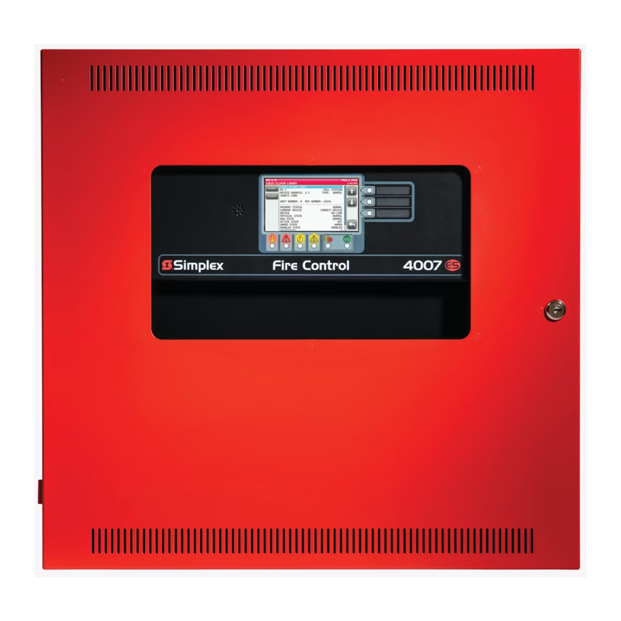
Simplex 4007ES (4007-9101, 4007-9201) Manual
- Programmer's manual (168 pages) ,
- User & installation manual (44 pages) ,
- Operator's manual (34 pages)
Advertisement
- 1 Introduction
- 2 User Interface
- 3 Alarm Conditions
- 4 Supervisory and Trouble Conditions
- 5 Main Menu
- 6 User Access Level
- 7 System Info
- 8 Panel Setup
- 9 Alarm Log
- 10 Trouble Log
- 11 Search
-
12
Diagnostics
- 12.1 Diagnostic Screen Buttons
- 12.2 HW Reset
- 12.3 Restart
- 12.4 WalkTest
- 12.5 Piezo Silence
- 12.6 Cfig Download
- 12.7 Earth Fault Search
- 12.8 Earth Fault Latch
- 12.9 NAC Miswire Test
- 12.10 Duplicate Device Search
- 12.11 Weak Answer Search
- 12.12 TrueAlert Test
- 12.13 TrueAlert NAC Test
- 12.14 CO Algorithms
- 12.15 Install Mode
- 12.16 Network Status
- 12.17 NetDiag
- 13 Report Menu
- 14 Cautions, Warnings, and Regulatory Information
- 15 Documents / Resources
Introduction
The user interface is touchscreen based on 4007-9101 4007ES and 4007-9201 4007ES Hybrid Fire Alarm Control Panels (FACP). The various functions of the panel are access-level protected, thus restricting access to sensitive features to appropriate personnel only.
The 4606-9202 and the 4606-9205 are Color Touchscreen LCD Annunciators for 4007ES panels. They provide remote annunciation of the FACP status. Access to Annunciator switch functions can be enabled or locked using the keyswitch. A maximum of six color touchscreen annunciators can be installed on a 4007ES panel.
Refer to the Programmer's manual, 579-1167, for more information on how to enable/disable the operations on the Color Touchscreen LCD Annunciator.
Note: The user interfaces for the 4007ES and the 4007ES Hybrid FACPs are identical and referred to collectively as 4007ES in this document.
User Interface
The user interface is used to operate the FACP.
Figure 1: 4007ES User Interface

Figure 2: Color Touchscreen LCD Annunciator User Interface

Table 1: Components of the FACP User Interface
| Component | Description |
| Touchscreen | Used as the panel's input/output interface. |
| Piezo | Emits tones during Alarm, Trouble, Pri2 and Supervisory conditions. |
| Bi-color User- Defined LEDs | Associated with the three custom-configured user buttons. The top two LEDs can be either yellow or red. The bottom LED can be either yellow or green. |
| Slide-in Labels | Used to describe the functions of the user buttons. |
| Fire LED | Indicates a fire alarm when flashing and an acknowledged alarm when steady on. |
| Priority 2 LED | Indicates a Priority 2 condition when flashing and an acknowledged condition when steady on. |
| Supervisory LED | Indicates a Supervisory condition when flashing and an acknowledged condition when steady on. |
| Trouble LED | Indicates a Trouble state when flashing and acknowledged Trouble when steady on. |
| Alarm Silence LED | Indicates an alarm has been silenced when steady on. |
| Power LED | Indicates AC power is applied to the panel when steady on. |
| Keyswitch | (Only on the Color Touchscreen LCD Annunciator) Allows interaction with the panel if the key is used. |
Alarm Conditions
An alarm condition occurs when an initiating device (such as a manual pull station, smoke detector, etc.) activates. The panel indicates the presence of the alarm condition by:
- Flashing the Fire
![]() or PRI2
or PRI2 ![]() LEDs.
LEDs. - Displaying messages on the user interface.
- Activating the building's notification appliances (horns and strobes).
Screen Buttons
Figure 3: Alarm conditions screen buttons

Recognizing an Alarm Condition
When an alarm condition occurs, the following events occur at the user interface:
Table 2: Alarm condition events
| Fire | PRI2 |
| The Fire LED begins to blink | The PRI2 LED begins to blink |
| The piezo begins to sound a pulsating tone | The piezo begins to sound a pulsating tone |
| The user interface displays the Fire Alarm in System screen, which shows the list of all the triggered alarms. | The user interface displays the PRI2 Alarm in System screen, which shows the list of all the triggered alarms. |
Note: A zone groups multiple points together, and the Zone Fire and Zone PRI2 Alarms lists display all the zones where alarm conditions occurred. You can view the points that triggered the alarms within each zone by pressing on any given zone from the list.
Figure 4: Alarm Condition Screen (Fire Alarm Shown as an Example)

Pressing anywhere on the user interface touchscreen silences the piezo. Until the alarm conditions are acknowledged, it re-sounds after one minute of inactivity at the user interface.
Processing Alarms
There are three actions that can be taken when an alarm condition occurs:
- Acknowledge an Alarm
- Silence the Alarm
- Reset the System
Each step is explained in detail in the rest of this section.
Acknowledge an Alarm
You can configure two types of acknowledging modes on the panel:
Global Acknowledge
All the zones inside the Zone Alarm list are acknowledged at the same time.
Individual Acknowledge
Each zone inside the Zone Alarm list is acknowledged separately.
Global Acknowledge
Tap the ACK button.
Figure 5: Acknowledge

Note: Acknowledging an alarm does not silence the horns. Silence an alarm as shown in Silence the Alarm.
Individual Acknowledge
Tap the unacknowledged alarm from the Zone Alarm List.
Figure 6: Unacknowledged alarm

Note: The alarms that have not been acknowledged display the text Press to acknowledge on the top right of the button.
Silence the Alarm
Silencing an alarm turns off all the audible notification appliances that are programmed to turn off when it is pressed.
- Tap theAlarm Functions button.
Figure 7: Alarm functions button

- Press theAlarm Silence button.
Figure 8: Alarm Silence button

- Confirm the selection.
![]()
Ensure the evacuation of the building is complete before silencing the alarm.
Figure 9: Confirming selection
![]()


Reset the System
Resetting the system allows it to return to a normal state after alarm activation.

Reset the system only after the source of the alarm is determined and dealt with.
- Tap the Alarm Functions button.
Figure 10: Alarm functions button

- Tap theSystem Reset button.
Figure 11: System reset

- Confirm the selection.
Figure 12: Confirm
![]()


Note:
- If a zone or device has reset successfully, the user interface returns to its normal display.
- If a zone or device remains in alarm when you reset the system, the system reset aborts. A message confirming the abort displays on the user interface.
Viewing the Alarm Condition Details
Each alarm condition contains detailed information on the point, or points, that have triggered it. To access that info:
- Tap on a desired alarm condition from theFire Alarm in System screen. That alarm condition can either be a point or a zone containing a variety of points. A point in alarm is shown as an example.
Figure 13: Viewing the Alarm condition

- Take the necessary actions, using the buttons available at the point details screen. A pull station point is shown as an example here.
Figure 14: Point details screen


Supervisory and Trouble Conditions
A Supervisory condition indicates a problem with the building's automatic sprinkler system or some other system used for the protection of life and property.
A Trouble condition indicates the presence of a circuit break, or a ground, within a system point, or somewhere between the FACP and one of its points. It can also be used to indicate a failure in the system that requires attention.
The panel indicates the presence of a Supervisory ![]() or Trouble
or Trouble ![]() condition by:
condition by:
- Displaying messages on the user interface.
- Flashing the Supervisory or Trouble LEDs.
Supervisory and Trouble Screen Buttons
Figure 15: Screen buttons for Supervisory or trouble conditions

Recognizing a Supervisory and a Trouble Condition
When a Supervisory or Trouble event occurs, the following events occur at the user interface:
Table 3: Supervisory or Trouble condition events
| Supervisory | Trouble |
| The Supervisory LED begins to blink. | The Trouble LED begins to blink. |
| The piezo begins to sound a continuous tone. | The piezo begins to sound a continuous tone. |
| The user interface displays the Supervisory in System screen, which shows the list of all the Supervisory conditions. | The user interface displays the Trouble in System screen, which shows the list of all the Troubles. |
Figure 16: Supervisory or Trouble Condition Screen (Trouble Condition shown as an example)

Note: A zone groups multiple points together and the Zone Supervisory or Zone Trouble list displays all the zones where Trouble or Supervisory conditions occurred.
Processing Supervisory and Trouble Conditions
When a Supervisory or a Trouble event occurs, it needs to be acknowledged and the cause of the event resolved for the system to return to normal. Two types of acknowledging modes can be configured on the panel.
- Global Acknowledge: All the zones inside the Zone Supervisory or Zone Trouble lists are acknowledged at the same time.
- Individual Acknowledge: Each zone inside the Zone Alarm List are acknowledged separately.
Note: A zone groups multiple points together and the Zone Supervisory or Zone Trouble list displays all the zones where Trouble or Supervisory conditions occurred.
Global Acknowledge
Figure 17: Acknowledge

Tap the ACK button.
Note: Acknowledging an alarm does not silence the horns. Silence an alarm as shown in Silence the Alarm.
Individual Acknowledge
Figure 18: Unacknowledged Trouble

Tap the unacknowledged Trouble from the events list.
Note: Unacknowledged Troubles display the text Press to acknowledge on the top right of the button.
Viewing the Supervisory and Trouble Conditions Details
Each Supervisory or Trouble condition contains detailed information on the point (or points) that have triggered it. To access that info, do the following:
Note: Trouble screen is used as an example.
- Tap on a desired Trouble condition from theTrouble in System screen. That Trouble condition can either be a point or a zone containing a variety of points. A point in Trouble state is shown as an example.
Figure 19: Trouble condition

- Take the necessary actions, using the buttons available at the point details screen. A Time and Date Trouble is used as an example.
Figure 20: Time and Date Trouble example
![]()

Main Menu
To access Main Menu functions, do the following:
- Tap anywhere on the touchscreen to remove the screensaver image.
- Tap theMenu button on the user interface if you are using the user influence.
Main Menu Screen Buttons
Figure 21: Main Menu screen buttons

Note: * User Buttons can be assigned to custom panel functions. Each function can be assigned to a task, such as Manual evacuation or City Disconnect. User buttons that have not been assigned a function do not appear on the user interface.
Figure 22: Main Menu screen

Table 4: Description of Main Menu icons
| Main Menu Icons | Description |
| System Info | Use the System Info function to obtain detailed information regarding the panel and its components. |
| Panel Setup | Use the Panel Setup function to modify the configuration of the basic components. |
| Alarm Log | The Alarm Log screen contains the list of alarms that the panel has received. |
| Trouble Log | The Trouble Log screen contains the list of Troubles that the panel has received. |
| Search | Use the Search screen to look for any configured point on the system controlled by the panel. |
| System Reset | Tap the System Reset button to reset all devices in alarm and clear all acknowledged Alarms, Troubles and Supervisory conditions. |
| Hardware Reset | Tap the Hardware Reset button to re-initialize the state of certain hardware components. A hardware reset is typically used to reset Class A Troubles after the problem causing the Trouble is resolved. |
| Diagnostics | Use the Diagnostics function to run tests on the panel and the connected devices. |
| User Access Level | Tap the User Access Level button to access the login screen. From this screen, the user can log into the panel with a desired access level, or log out of the access level that he is currently in. |
| Lamp Test | Tap the Lamp Test button to light all 9 LEDs on the front panel for 5 seconds. The three dual-colored LEDs blink alternately. The touch screen alternates between red, green and blue. |
| Report Menu | Tap the Report Menu button to generate various types of reports on the system points. |
User Access Level
Tap the User Access Level button to access the login screen, where the user can log in to the panel with a desired access level, or log out of the current access level.
Note:
- Four access levels can be used to log in to the panel, with the lowest, User Access Level 1, being the default.
- Only some functions are available at each access level. Figure 25 shows functions with associated default user access levels.
- The ES Panel Programmer can be used to modify default user access levels for each function, or set user access level passcodes. Refer to document 579-1167:4007ES Panel Programmer's Manual for more details.
Figure 23: User access screen buttons
![]()
Figure 24: User Access Level Screen


Log Out

Tap the Log Out button to log out of the current user access level. Once logged out, the user is returned to Access Level 1.
Figure 25: User Access Level Chart

System Info
Use the System Info function to obtain detailed information regarding the panel and its components. Tap on a menu icon to access that option's main screen. Refer to User Access Level for access levels required to use each option inside the System Info screen.
System Info Screen Buttons
Figure 26: System info screen buttons

Figure 27: System info screen

Card Revisions

Tap the Card Revisions button to see a list of all the cards (modules) installed in the panel.
Software Revisions

Tap the Software Revisions button to see the latest master revisions loaded on the panel.
Panel Serial Number

Tap the Serial Number button to see the serial number of the panel.
Card Status

Tap the Card Status button to see the status of the different cards installed in the panel.
System Files Info

Tap the System Files Info button to see the latest master revisions loaded on the Remote Annunciator.
IP Info

Tap the IP Info button to see the IP and the MAC address of the 4007ES panel.
Panel Setup
Use the Panel Setup function to modify the configuration of the basic panel components.
Tap on a menu icon to access that option's main screen. Refer to User Access Level for access levels required to use each option inside the Panel Setup screen.
Panel Setup Screen Buttons
Figure 28: Panel setup buttons

Figure 29: Panel Setup screen

Swap Config

Tap the Swap Config button to access the following functions. These functions allow roll back to the previous versions of the panel firmware.
- Show Alternate Config Version: Tap this button to display the previous version of the panel firmware.
- Use Alternate Config Version: Tap this button to install the previous version of the panel firmware.
Set Time/Date

Tap the Set Time/Date button to access the screen where the date and time displayed at the panel can be updated:
- Press the button that corresponds to either day, month, year, hour, minute or second.
- Enter a new value using the touchscreen keypad.
- Repeat steps 1 and 2 for the date and time values that remain.
- Press theAccept button for the new date and time to take effect immediately.
Touchscreen Calibration

Tap the Touchscreen Calibration button to access the calibration screen and adjust the sensitivity of the user interface touchscreen. Follow these steps to adjust:
- Increase or decrease the touchscreen sensitivity by using the Scroll Up and Scroll Down buttons.
- Tap the Calibrate button and then tap the "+" signs that appear to adjust the precision of the touchscreen pressure sensors.
- Return to the System Menu screen.
Mass Storage

Tap the Mass Storage button to access the functions listed below. The USB key must be inserted in the USB Port slot of the 4007 CPU Card for the Mass Storage button to work.
- Job Backup: Tap this button to save the job currently loaded on the panel to the USB key.
- Save Reports: Tap this button to save reports to the USB key.
- Upgrade Status: Tap this button to see the progress of the software upgrades.
- SnapShot Recovery: Tap this button before doing a system upgrade to copy the software types currently loaded on the panel to the USB key.
To upload these software types back on the panel, re-insert the USB key in the USB Port of the 4007 CPU Card and tap the SnapShot Recovery button. - Eject USB: Tap this button to safely remove the USB from the panel.
System Upgrade

With a USB thumb drive inserted, tap the System Upgrade button to open the System Upgrade screen which contains a list of all the panel software types and their current revisions. The software type in bold and colored green indicates that its more recent version can be loaded on the panel.
Note: The System Upgrade screen is launched by default when the USB key is inserted in the USB Port of the 4007 CPU Card.
- Use theSelect All button to select all of the software types listed in the table.
- Use theChange Job button to load a new job on the panel.
- Use theRefresh Reset button to refresh the software type list.
- Use theProcess Upgrade button to proceed with the change.
Alarm Log
The Alarm Log screen contains a list of alarms that the panel has received. Refer to Figure 25 for access levels required for each option inside the Alarm Log screen.
Alarm Log Screen Buttons
Figure 30: Alarm Log buttons

Figure 31: Alarm Log Screen

Clear

Tap the Clear button to erase all entries in the Alarm Logs screen.
Use the Clear button only after the alarms have been investigated.
Trouble Log
The Trouble Log screen contains a list of Troubles that the panel has received. Refer to User Access Level for access levels required for each option inside the Trouble Log screen.
Trouble Log Screen Buttons
Figure 32: Trouble screen buttons

Figure 33: Trouble Log Screen

Clear
Tap the Clear button to erase all entries in the Trouble Logs screen.
Use the Clear button only after the Troubles have been investigated.
Search
Use the Search screen to look for configured points under panel control. Refer to User Access Level for access levels required for each option inside the Search screen.
Search Screen Buttons
Figure 34: Search Screen Buttons

Figure 35: Search screen

New Search: Search for a Specific Point
The point search keypad opens automatically when the Search screen is accessed or by pressing the New Search button.
- Select the desired point type. For example, to select an IDNet point, press on theIDNet button.
- Select the desired point number. For example, to select an IDNet point M1-1-0, enter "1-1-0".
Note: Point numbers are first generated when the ES Panel Programmer is used to program points into the panel.
Figure 36: Search screen
![]()
- Tap theAccept button to execute the search. Tap the Erase button to erase the last character entered. Use the Return button to return to the Search screen.

New Search: Browse the List of Configured Points
- If opened, close the keypad by pressing anywhere outside the keypad. You will see a list of all the points configured on the network.
- Use the Scroll Up and Scroll Down buttons to navigate the list, the Accept button to get more details on a point, and the Return button to return to the System Menu screen.
Diagnostics
Use the Diagnostics function to run tests on the panel and the devices. Refer to User Access Level for access levels required for each option inside the Diagnostics screen.
Diagnostic Screen Buttons
Figure 37: Diagnostic screen buttons

Figure 38: Diagnostic screen 1

Figure 39: Diagnostic screen 2

Note: NetStat is only available when the FACU is part of an ES Net Network.
HW Reset
Tap the Hardware Reset button to re-initialize the state of certain hardware components. A hardware reset is typically used to reset a Class A Trouble after the problem causing the Trouble is resolved.
Note: If you attempt to perform a hardware reset without first fixing the problem causing the Trouble, the hardware reset fails and the Trouble re-appears.
Restart

Tap the Restart button to restart the panel by Warm Start or Cold Start.
- Warm Start preserves the logs and the disabled status of any points that are in disabled state.
- Cold Start clears all history logs and re-enables any points that were previously disabled.
WalkTest

Tap the WalkTest button to open the WalkTest Settings screen, which contains Walktest groups configured by technicians for use during maintenance testing. The following functions are available:
- Tap theNext Group button to select the next WalkTest group.
- Tap thePrev Group button to select the previous WalkTest group.
- With an item in the WalkTest group selected, tap theSelect Item button to open a new screen where information and additional functions for that item are available.
Piezo Silence

Tap the Piezo Silence button to access the Piezo Silence Menu screen, where the On or Off buttons can be used to control the piezos at the panel and turn the Remote Annunciator's piezo on or off.
Cfig Download

Tap the Cfig Download button to access the Configuration Menu screen. Inside, the following functions are available:
- Tap the Enable button to allow a job download to a remote panel.
- Tap the Enable All button to allow a job download to all the remote panels.
- Tap the Disable button to disable the option of a job download to a remote panel.
- Tap the Revert button to access the following functions:
- Tap the Alt Cfig button to see the details of the last job used by the panel.
- Tap the Swap button to swap the current job for the one used by the panel last.
- Tap the NoSwap button to move back to the Configuration Menu screen.
Earth Fault Search

Tap the Earth Fault Search button to access the Earth Fault Search? screen, which can be used to test for earth faults in the circuit. The following functions are available:
- Press the Location button to display a list of cards that can be tested for earth faults.
- Press the IDNet button to display a list of IDNet channels that can be tested for earth faults.
- Press the LastResults button to view the results of the last earth fault test.
Earth Fault Latch

Tap the Earth Fault Latch button to access the Earth Latch Menu screen, which can be used to latch intermittent earth fault Troubles to the panel. This allows the panel to consistently display a Trouble instead of each time it re-occurs. The following functions are available:
- Tap the Off button to disable the Earth Latch function.
- Tap the On button to enable the Earth Latch function.
- Tap the ViewRaw button to view the locations of the raw earth faults.
NAC Miswire Test

Tap the NAC Miswire Test button to access the NAC Test Menu screen, which can be used to perform a wiring test on the Notifications Appliance Circuits (NAC). The following functions are available:
- Tap the All button to test all the NACs at once.
- Tap the Single button to test each NAC separately.
Duplicate Device Search

Duplicate Device Search button to access the Duplicate Dev Menu screen, where On or Off buttons can be used to turn the detection of duplicate devices on IDNet channels on or off.
Weak Answer Search

Tap the Weak Answer Search button to access the Weak Answer Menu screen, where the On or Off buttons can be used to turn the detection of weak answering devices on IDNet channels on or off.
TrueAlert Test
Tap the TrueAlert Test button to access the TrueAlert Tests Menu screen, where tests for TrueAlert addressable notification appliances can be performed. The following functions are available:

- Tap the TrueAlert ES Self-Test? button, and then use the Run Self-Test? button to run Self-Test, or use the View Test Results? button to view the results for TrueAlert appliances.
- Tap the TrueAlert Device LEDs Test? button, and then use the On or Off buttons to turn the TrueAlert appliance LEDs on or off.
- Tap on the TrueAlert Device Test Mode? button, and then use the On or Off buttons to place the TrueAlert appliances in or out of Test Mode.
- Tap the TrueAlert Silent Test Mode? button, and then use the On or Off buttons to choose whether you want to place the TrueAlert appliances in Silent Test Mode or not. In Silent Test Mode, the device's sounders are disabled.
TrueAlert NAC Test

Tap the TrueAlert NAC button to perform a TrueNAC Voltage Drop Test. This test ensures that 4906 devices are installed properly by determining the line voltage for compatible notification appliances that are connected to a TrueAlert Power Supply (TPS) Signaling Line Circuit (SLC), under worst-case panel operating conditions. After pressing the TRUENAC button, the following options are available:
- All: Press this button to test all the TPS SLC lines at once. After pressing this button, these options become available:
- HornON: Press this button to set the horns to high volume during the test.
- HornOFF: Press this button for a silent system test.
- Single: Press this button to test each TPS SLC line separately.
Note:
- The results of the TrueNAC Voltage Drop Test are displayed on the screen. A Troublecondition is generated for every device that has failed the test.
- If Horns are on, the panel will perform two passes: one with horns on and one withhorns off. This is done to enhance the accuracy of A/Vs measurement.
CO Algorithms

Tap the CO Algorithms button to access the IDNet CO Algorithms Menu screen. The following functions are available:
- Tap the Off button to disable the IDNet CO Algorithms. This is useful when smoke testing the IDNet CO devices.
- Tap the On button to enable the IDNet CO Algorithms.
Install Mode
Install Mode is a feature that minimizes the number of Troubles that occur when the system is being installed or is undergoing extensive service, by placing points and cards that can cause Troubles in Install Mode during those times. Install Mode raises a single "INSTALL MODE ACTIVE" Trouble, regardless of the number of items in it.
Tap the Install button to access the Install Mode Menu screen. The following functions are available:

- Tap the IViewMod button to view all the items in Install Mode.
- Tap the IAddMiss button to add items to Install Mode.
- Tap the IAddOpens button to add all open circuits to Install Mode.
- Tap the IRemvNorm button to remove an item from Install Mode.
- Tap the IRemvAll button to remove all the items from Install Mode.
Network Status
The Network status screen displays information about common network issues. For each type of network issue, a list of nodes and ports currently experiencing errors is displayed, if applicable.
To view the network status for each type of network issue, do the following:

- Tap the NetStat button to access the Net Status Menu screen.
- Use the arrow buttons to navigate to a type of network issue and tap Select Item.
You can view the following network issues:
- Links Down: a list of all nodes and ports that have a link down condition
- Miswired: a list of all nodes and ports that have a miswire condition
- Version Mismatches: a list of all nodes this node is version mismatched with
- Extra Nodes: a list of extra nodes on the network
- Duplicate Nodes: a list of duplicated nodes on the network
- Missing Nodes: a list of all missing nodes, that is not in attendance
- Ground Faults: a list of all nodes and ports with Ground Fault condition
NetDiag
Tap the NetDiag button to access the Net Diagnostics Menu screen, where the following functions for analyzing and gathering network information are available. Use the arrow buttons to navigate to each option. To select an option, tap the Select Item button when it is highlighted.

- Diagnostics by Node: Use this option to choose a node and display its details.
- Net Diag Logging: Use this option to choose which network parameters to log, and where these logs are saved.
- Network Tallies: Use this option to choose whether to view or clear network tallies. This applies only to 4120 Networks.
- Diag Tbls Missing Node Troubles: Use this option to enable or disable missing node Troubles.
- Diagnostic Message Options: Use this option to select the node to which diagnostic messages are sent, the message directions, and the number of message retries. This applies only to 4120 Networks.
- Relay Mode: Use this option to choose whether or not the current node is in Relay Mode. This applies only to 4120 Networks.
- Repeater/Reset for All Nodes: Use this option to reset/restore nodes, or to put the nodes in Repeater Mode.
- Current Details of Network: Use this option to obtain information on the number of nodes configured, communicating and in Repeater Mode, as well as the Monitor node, Left End node, Right End node, and the node's Repeater source. Use this option to also determine the network topology, attendance, and the node IDs.
- Stop ALL Net Diag Functions: Use this option to stop all the network diagnostic functions that are currently running.
Report Menu
Press the Report Menu button to access the Report Menu screen, where various types of reports on the system points can be generated. To generate a report:
- Press theReport Menu button from the Main Menu screen to open the Report Menu screen, see Screen Buttons.
- A report can either be saved to a USB key or printed. See below for both options:
Table 5: Printing and saving report
| Printing a Report | Saving a Report to a USB Key |
|
|
Note: Pressing a report button without first inserting a USB key or choosing a printer generates an error message stating that hardware could not be found.
Refer to User Access Level for access levels required to use each option inside the Report Menu screen.
Screen Buttons
Figure 40: Screen buttons

Figure 41: Report menu screen

Table 6: Report Menu Screen Buttons
| Button | Description |
| Alarm Log | Tap the AlarmLog button to generate a report containing the list of alarms that the panel has received. |
| Trouble Log | Tap the TroubleLog button to generate a report containing the list of Troubles that the panel has received. |
| TrueAlarm Status | Tap the TrueAlarm Status button to generate a report containing the status of the various TrueAlarm devices connected to the panel. The report includes the following information:
|
| TrueAlarm Service | Tap the TrueAlarm Service button to generate a report which contains the following information:
|
| TrueAlert NAC Test | Tap the TrueAlert NAC Test button to generate a report which contains the following information for each TrueAlert device:
|
| TrueAlert Status | The TrueAlert Status Report can be created after the TrueNAC Voltage Drop Test is run. Tap theTrueAlert Status button to access the Print TAlert Status screen. The All button can be used to generate the report containing the status for all devices. The Last button can be used to generate a report containing the status of the last test. The report contains the following information:
|
| TrueAlarm CO | Tap the TrueAlarm CO button to generate a report with the following information regarding the TrueAlarm CO devices:
|
| Active List | Tap the Active List button to access the Print Active List screen, where the Install Mode button can be used to generate a report containing the following Install Mode list information:
|
| Verification Tally | Tap the Verification Tally button to generate a report containing the following information for each device supporting the alarm verification:
|
| TrueAlert Self-Test | Tap the TrueAlert Self-Test button to access the Print TA Self-Test screen to generate a report containing the Self-Test results for the TrueAlert appliances. Tap the ALL button to generate a report with the results for all appliances. Tap the LAST button to generate a report with the result for the last device. |
Cautions, Warnings, and Regulatory Information
READ AND SAVE THESE INSTRUCTIONS Follow the instructions in this installation manual. These instructions must be followed to avoid damage to this product and associated equipment. Product operation and reliability depend upon proper installation.
 DO NOT INSTALL ANY SIMPLEX™ PRODUCT THAT APPEARS DAMAGED
Upon unpacking your Simplex product, inspect the contents of the carton for shipping damage. If damage is apparent, immediately file a claim with the carrier and notify an authorized Simplex product supplier.
 ELECTRICAL HAZARD
Disconnect electrical field power when making any internal adjustments or repairs. All repairs should be performed by a representative or an authorized agent of your local Simplex product supplier.
 STATIC HAZARD
Static electricity can damage components. Handle as follows:
- Ground yourself before opening or installing components.
- Prior to installation, keep components wrapped in anti-static material at all times.
Documents / ResourcesDownload manual
Here you can download full pdf version of manual, it may contain additional safety instructions, warranty information, FCC rules, etc.
Advertisement


Need help?
Do you have a question about the 4007ES and is the answer not in the manual?
Questions and answers