Table of Contents
Advertisement
5122722/04
INSTALLER AND OWNER GUIDE
Please keep me in a safe place for future use.
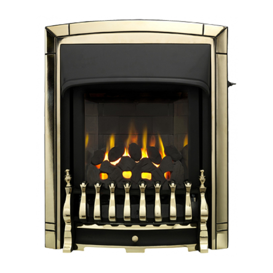
Model 940
Inset live fuel effect gas fire
Incorporating the VALOR
CONTROL
Fitted with one of the following fascia.
Adorn, Dream, Icon
Visage
or
(GC No. 32-032-71)
We trust that this guide gives sufficient details to enable this appliance to be
installed, operated and maintained satisfactorily. However, if further information is
required, our Valor Technical Helpline will be pleased to help.
Telephone 0844 8711 565 (National call rates apply in the United Kingdom).
In the Republic of Ireland Telephone 0044 844 8711 565.
©
GDC Group Ltd. 2011
Advertisement
Chapters
Table of Contents

Related Manuals for Valor 940


Summary of Contents for Valor 940
- Page 1 We trust that this guide gives sufficient details to enable this appliance to be installed, operated and maintained satisfactorily. However, if further information is required, our Valor Technical Helpline will be pleased to help. Telephone 0844 8711 565 (National call rates apply in the United Kingdom).
- Page 2 Warning: Any person who does any unauthorised act in relation to a copyright work may be liable to criminal prosecution and civil claims for damages. Valor, Erdington, Birmingham B24 9QP www.firesandstoves.co.uk Because our policy is one of constant development and improvement, details may vary slightly from...
- Page 3 BS EN ISO 9001 quality system accepted by the British Standards Institute. The Highest Standards Valor is a member of SBGI and HHIC (Heating and Hot water Industry Council) that work to ensure high standards of safety, quality and performance. Careful Installation This gas fire must be installed by a competent GAS SAFE REGISTER operative in accordance with this installer guide.
- Page 4 INSTALLER GUIDE INSTALLER GUIDE FOR OWNER GUIDE SEE PAGES 48 TO 60 Page 4 © GDC Group Ltd. 2011...
-
Page 5: Table Of Contents
INSTALLER GUIDE CONTENTS Section Page INSTALLER GUIDE 4 - 47 OWNER GUIDE 48 - 60 1. SAFETY AND UNPACKING 2. APPLIANCE DATA AND EFFICIENCY 2.1 General information. 2.2 Efficiency. 3. GENERAL INSTALLATION REQUIREMENTS 3.1 Regulations, Standards and Law. 3.2 Ventilation requirements. 3.3 The Atmosphere sensing device (ASD). -
Page 6: Installer Guide
INSTALLER GUIDE CONTENTS (Continued) Section Page 10. BURNER AND SUPPLY PIPE INSTALLATION 10.1 Burner and supply pipe installation. 10.2 Preliminary burner checks. 10.3 Inlet pressure check. 11. CERAMIC WALLS INSTALLATION 12. FASCIA AND CONTROL LINKAGE 13. FITTING THE CERAMIC FUEL EFFECT 14. -
Page 7: Safety And Unpacking
INSTALLER GUIDE 1. SAFETY AND UNPACKING Before continuing any further with the installation of this appliance please read the following guide to manual handling. The lifting weight (kg) of this appliance is as below: Model Heat Engine Firefront Combined Weight Adorn 11.5 16.6... -
Page 8: Appliance Data And Efficiency
: Model Efficiency % (Gross) 940 when converted to LPG. The gross calorific value of the fuel has been used for this efficiency calculation. The test data from which it has been calculated has been certified by Advantica Certification services (0087). -
Page 9: General Installation Requirements
INSTALLER GUIDE Conversion factor from net to gross efficiency Natural Gas 0.901 0.921 3. GENERAL INSTALLATION REQUIREMENTS 3.1 Regulations, Standards and Law. The installation must be in accordance with these instructions. For the user’s protection, in the United Kingdom it is the law that all gas appliances are installed by competent persons in accordance with the current edition of the Gas Safety (Installation and Use) Regulations. -
Page 10: Ventilation Requirements
INSTALLER GUIDE b) All relevant national and local rules in force. Where no specific instructions are given, reference should be made to the relevant British Standard Code of Practice. 3.2 Ventilation requirements. Normal adventitious ventilation is usually sufficient to satisfy the ventilation requirements of this appliance. -
Page 11: Fireplace Preparation
INSTALLER GUIDE 3.6.2 Any chimney damper or restrictor should be removed. If removal is not possible, they must be secured in the open position. 3.7 Fireplace preparation. 3.7.1 If the fireplace opening is an under floor draught type, it must be sealed to stop any draughts. -
Page 12: Fireplace Clearances
INSTALLER GUIDE 3.9 Fireplace clearances. 3.9.1 Adorn model only The minimum height from the base of the fireplace opening to the underside of any shelf made from wood or other combustible materials is shown in figure 2. Visage, Dream and icon models only. The minimum height from the base of the fireplace opening to the underside of any shelf made from wood or other combustible materials is shown in figure 3. - Page 13 INSTALLER GUIDE 3.9.2 The minimum allowable distance from the outside of the appliance fascia to a corner wall having combustible material or any other combustible surface which projects beyond the front of the appliance is shown in figure 4. A 10mm access clearance from a non-combustible surface is necessary at the left side (See figure 4).
-
Page 14: Installation Options
INSTALLER GUIDE 3.10 Installation options. In the United Kingdom, as supplied, the appliance can be installed in the following situations: - 3.10.1 Conventional fireplace and hearth. To a fireplace complete with surround and hearth as shown in figure 5 and complying with BS1251 after removal of the fireback and sufficient material behind the fireback for a debris catchment space. - Page 15 INSTALLER GUIDE 3.10.1.1 ‘Hole-in-the-wall’ Installations It is recommended that a hearth should be installed as in section 3.8. Icon firefront If when using the Icon firefront a hearth is not fitted, the fire must be installed so that the distance from the base of the fireplace opening in the wall to the finished floor level is at least 100mm.
-
Page 16: Flues
INSTALLER GUIDE 3.10.2 Metal flue box and hearth. The appliance can be installed to a fireplace incorporating a metal flue box complying with the constructional requirements of the current edition of BS 715 and with a flue conforming to BS EN 1856 part 1. -
Page 17: Propane Fires
INSTALLER GUIDE 175mm diameter flue pipe. See BS6461 Part 1 for suitable materials. Single wall, twin wall or flexible flue liner with a minimum diameter of 125mm. The materials to be used are stainless steel or aluminium as specified in BS EN 1856 Part 1. -
Page 18: Pack Contents
INSTALLER GUIDE 4. PACK CONTENTS Carefully remove all the contents. Take special care in handling the ceramic pieces. Take care not to bend or distort the slide control linkage when handling the fascia. Check that all the listed parts are present and in good condition. The items required for this appliance are packed in sections. - Page 19 INSTALLER GUIDE Figure 9. Pack contents Page 19 © GDC Group Ltd. 2011...
- Page 20 INSTALLER GUIDE Section 2 - Adorn fascia pack contains: Section 2 - Visage fascia pack contains: Fascia with sliding control. Fascia with sliding control. Bottom front cover casting. Fire front casting. Outlet baffle. Outlet baffle. Burner tray trim Figure 9. Pack contents continued Page 20 ©...
-
Page 21: Fireplace Check
INSTALLER GUIDE Section 2 - Dream fascia pack contains: Section 2 - Icon fascia pack contains: Fascia. Fascia with sliding control. Bottom front cover casting Bottom front cover. In accessory pack Top heat shield. Outlet baffle. Knurled screws for bottom front Burner tray baffle. -
Page 22: Ignition Check
INSTALLER GUIDE 6. IGNITION CHECK Before attempting to install, it is worth checking that the electronic ignition system performs satisfactorily. Fit the battery to the ignition block located below the burner tray at the left side (See figure 10). The locations for the +ve and -ve terminals are marked on the battery holder. -
Page 23: Preparing Appliance For Installation
INSTALLER GUIDE 8. PREPARING APPLIANCE FOR INSTALLATION 1. Detach the burner unit from the convection box by removing two screws (See figure 12). Lift the burner unit clear. 2. Fit the two “U” section seals to the bottom edges of the convection box side flanges (See figure 13). - Page 24 INSTALLER GUIDE 6. The Adorn, Visage and Dream models have an outlet baffle supplied with the appliance fascia. Fit this to the convected air outlet of the appliance using the three self tapping screws supplied with the fascia (See figure 15). The Icon model has a heat baffle supplied with the appliance fascia.
- Page 25 INSTALLER GUIDE 9. There is a length of self adhesive foam seal supplied with the fire. This will need to be fitted to the outer rear edges of the side and top flanges of the convection box. Cut a 485mm length of foam seal.
-
Page 26: Convection Box Installation
INSTALLER GUIDE 9. CONVECTION BOX INSTALLATION 9.1 Method 1 - Front fixing to fireplace surround. 1. Make sure that the fireplace front surround area is sound enough to take the fibre / wooden plugs and woodscrews. If necessary, make sound with suitable cement. 2. - Page 27 INSTALLER GUIDE should be drilled within the range of positions shown in figure 21 using a suitably sized masonry drill bit for the wall plugs supplied. The holes should be equidistant each side of the centre line of the fireplace to ensure that the appliance finishes centrally in the opening when tension is applied to the cables.
-
Page 28: Sealing Floor Front - All Installations
INSTALLER GUIDE 10. Fit a cable retainer over the bottom end of each cable. 11. Pull each cable taut. Push the cable retainers hard up against the back panel. The end of the cable adjuster will pass into the hole. Tighten the screws in the retainers so that they clamp the cables in position. -
Page 29: Burner And Supply Pipe Installation
INSTALLER GUIDE 10. BURNER AND SUPPLY PIPE INSTALLATION 10.1 Burner and supply pipe installation. 1. Refit the burner unit to the convection box with two screws. 2. Connect the supply line to the appliance. 3. Turn on the gas supply and pressure check the installation pipework for gas soundness. -
Page 30: Inlet Pressure Check
INSTALLER GUIDE 10.3 Inlet pressure check. The appliance is pre-set to give the correct heat input at the inlet pressure shown in section 2 of this manual. No adjustment is necessary. 1. Ensure that the fire is turned OFF before removing the pressure test point sealing screw. -
Page 31: Fascia And Control Linkage
INSTALLER GUIDE 2. Remove four screws from the spillage plate sides (See figure 30). 3. Remove the spillage plate by lifting it forward. 4. Fit the ceramic side walls against the side faces of the burner compartment. The bottom edges of the walls should rest in the ledges at the sides of the firebox. - Page 32 INSTALLER GUIDE 3. Place the fascia against the fireplace front surface so that the two retaining plates at the back of the fascia are above the two upper retaining brackets at the top of the convection box. Lower the fascia making sure that the rear retaining plates locate fully into the retaining brackets on the convection box (See figure 32).
- Page 33 INSTALLER GUIDE 12.2 Adorn, Icon and Visage fascias Carefully lift the fascia. Do not lift it by the slider control knob. Remove the tape securing the control linking bar to the fascia. Slide the control knob upwards as far as it will go. Make sure that the bottom of the linking bar is higher than the bottom of the fascia.
- Page 34 INSTALLER GUIDE front casting sideways, if necessary, to align the bottom fixing holes with those in the convection box. Fix the bottom of the casting to the convection box with two screws and washers (See figure 38). 12.2.3 Icon fascia Place the fascia against the fireplace front surface so that the two retaining plates at the back of the fascia are directly above the two upper retaining...
-
Page 35: Fitting The Ceramic Fuel Effect
INSTALLER GUIDE Figure 41. Control bar and pivot bracket (Shown with Adorn fascia) 13. FITTING THE CERAMIC FUEL EFFECT The installer and owner guide for the ceramic fuel effect is supplied with the ceramic fuel effect. It is important that the fitting guide for the ceramic fuel effect be placed inside or attached to this guide and handed to the customer following completion of the ‘Final review’... -
Page 36: Full Operating Checks
INSTALLER GUIDE 14.3 Icon front cover. Locate the top flanges of the bottom front cover behind the bottom edge of the fascia. Fix the sides of the cover to the fascia bottom corner brackets with the two knurled screws provided (See figure 43). -
Page 37: Check For Spillage
INSTALLER GUIDE 4. Gradually slide the control knob up to increase the burner setting. The burner should be at its maximum setting at the high heat position shown in figure 44. You should feel a check to the control knob movement at this position. 5. -
Page 38: Flame Supervision And Spillage Monitoring System
INSTALLER GUIDE 15.3 Flame supervision and spillage monitoring system. This pilot unit includes a system that will automatically shut off the gas supply if the pilot flame goes out or if there is insufficient oxygen due to spillage or poor ventilation. Check that the system operates properly as follows;... -
Page 39: Final Review
INSTALLER GUIDE 16. FINAL REVIEW COMPLETE THE INFORMATION IN THE WARRANTY AND SERVICE SECTION OF THE OWNER GUIDE (See last pages of the OWNER guide). 2. If a gap is visible between the inner sides of the fascia and the ceramic side walls, gently slide the walls forward. -
Page 40: Servicing & Parts Replacement
INSTALLER GUIDE 17. SERVICING & PARTS REPLACEMENT Always turn off the gas supply and allow the fire to cool completely before commencing any servicing (The appliance inlet ‘T’ connector incorporates an isolating valve). It is recommended that, at least once a year, the appliance is disconnected and the fireplace opening checked and cleared of any debris. -
Page 41: Checking The Aeration Setting Of The Burner
INSTALLER GUIDE 17.1 Checking the aeration setting of the burner. 1. The aeration shutter is factory set and should not require adjustment. If the shutter is not as shown in figure 46 and requires adjustment, loosen the two aeration shutter screws, slide the aeration shutter to the position shown in figure 46 and tighten the fixing screws. -
Page 42: To Remove The Fascia
INSTALLER GUIDE 17.4 To remove the fascia. 1. Remove the bottom front cover / fire front casting. 2. Detach the control-linking bar from the control pivot bracket by removing the knurled screw, which joins the control linking bar to the control pivot unit (See figure 49). -
Page 43: To Replace The Slider Control Knob
INSTALLER GUIDE Visage Adorn Icon Figure 52. Control slide fixings Dream model. The control slide unit is secured to the convection box and not the fascia. 1. Remove the fascia (See section 17.4). 2. Detach the slide unit by removing two screws securing the plastic slide mechanism to the convector box. -
Page 44: To Remove The Complete Burner Unit
INSTALLER GUIDE 17.7 To remove the complete burner unit. 1. Remove the bottom front, fire front castings and the fascia (See section 17.4). 2. Remove the ceramic fuel effect. 3. Close the isolating valve in the inlet ‘T’ connector. Support the inlet ‘T’ connector to avoid straining the pipework and disconnect the appliance from the ‘T’... -
Page 45: To Remove The Pilot Unit
INSTALLER GUIDE 5. Refit in the reverse order. If the microswitch leads cannot be easily attached to the interrupter block when it is fully tightened to the gas shut-off tap, slacken it and rotate to allow the leads to be fitted. Retighten making sure that the leads remain in place in the interrupter block. -
Page 46: To Remove The Gas Flow Rate Controller
INSTALLER GUIDE 8. If fitting a new tap, remove the hexagonal nut at the mounting bracket end of the old tap and fit to the replacement tap. Refit in the reverse order. When refitting, make sure that the tap spindle is in the correct relationship relative to the control pivot bracket. -
Page 47: To Replace The Burner
INSTALLER GUIDE 17.13 To replace the burner. (See figure 59). 1. Remove the burner unit (See section 17.7). 2. Support the elbow injector and unscrew the injector nut. 3. Remove the two screws from the burner clamping plate (See figure 59) 4. -
Page 48: Owner Guide
OWNER GUIDE OWNER GUIDE FOR WARRANTY AND SERVICE INFORMATION SEE PAGES 57 TO 60 Page 48 © GDC Group Ltd. 2011... - Page 49 OWNER GUIDE LIST OF CONTENTS Section Page SAFETY APPLIANCE DIMENSIONS AND CLEARANCES GAS CONSUMPTION OPERATING YOUR FIRE The Oxysafe flame sensing and flue blockage safety system. To light the fire. To turn the fire off. Lighting with a taper. CLEANING YOUR FIRE Metal parts.
-
Page 50: Safety
OWNER GUIDE SAFETY Do have the fire installed by a competent person. In the United Kingdom, installation must be in accordance with the latest edition of the Gas Safety (installation & use) Regulations. In the Republic of Ireland, installation must be in accordance with all national and local regulations in force. - Page 51 OWNER GUIDE ADORN MODEL ONLY Figure 1. Combustible shelf clearances for ADORN model only VISAGE, DREAM AND ICON MODELS ONLY Figure 2. Combustible shelf clearances for VISAGE, DREAM and ICON models only. Page 51 © GDC Group Ltd. 2011...
-
Page 52: Appliance Dimensions And Clearances
OWNER GUIDE APPLIANCE DIMENSIONS AND CLEARANCES See figure 1 & 2 Model Description Adorn Visage Icon Dream Height (mm) Width (mm) Depth into room (mm) Minimum mandatory clearance to combustible surfaces projecting beyond the front of appliance (mm). Recommended clearance to non-combustible surfaces for access purposes (mm). -
Page 53: Gas Consumption
Has a minimum natural gas input of 2.7kW (Gross) Has a minimum natural gas output of 1.34kW Model 940 when converted using kit number 0595211 Has a maximum propane gas input of 6.7kW (Gross) Has a maximum propane gas output of 3.9kW Has a minimum propane gas input of 4.3kW (Gross) -
Page 54: To Turn The Fire Off
OWNER GUIDE Until you can obtain a replacement battery the fire can be lit with a taper as described later in this guide. 2. Keep the control knob at the ignition position for a further ten seconds. This will prevent the flame-sensing device from shutting off the gas while its probe warms up as explained above. -
Page 55: Cleaning Your Fire
OWNER GUIDE CLEANING YOUR FIRE To maintain the high performance and quality finish of your fire please follow these guidelines: Before attempting to clean the fire, please remember to turn off the fire and wait for the appliance to cool. The fire will retain heat for some time before cleaning can begin. -
Page 56: Ceramic Fuel Effect Fitting
OWNER GUIDE CERAMIC FUEL EFFECT FITTING The installer and owner guide for the ceramic fuel effect is separate from this guide. The installer may have attached it to this guide or placed it inside. It is important that the installer and owner guide for the ceramic fuel effect is followed correctly. If replacing the ceramic fuel effect, where a new guide is supplied, follow the installer and owner guide supplied with the replacement fuel effect. -
Page 57: Regular Maintenance
OWNER GUIDE Regular maintenance. In order to achieve and maintain high levels of personal safety and performance efficiency, it is essential that the opening at the back of the fire and the flue are kept clear of any form of obstruction. It is possible that deposits of mortar or soot could fall and accumulate causing the flue to be blocked or restricted and so preventing proper clearance of dangerous exhaust fumes. - Page 58 OWNER GUIDE What you need to do if you experience a problem with the operation of the fire: You should always contact your installer first, because the cause of the fault may not be related to the fire. If your installer confirms that the fault is with the fire and they can’t repair it, our friendly customer service team is on hand to help.
- Page 59 OWNER GUIDE To be completed by Installer: Installer Details (Block Capitals) Installer Name Gas Safe Register Number. Company Name. Company Address Company Telephone number Company Fax number Figure 8. Page 59 © GDC Group Ltd. 2011...
-
Page 60: Owner Guide
OWNER GUIDE Model Serial number (Can be found on information label - See figure 8) A LABEL CONTAINING THE SERIAL NUMBER MAY HAVE BEEN PLACED INSIDE THIS BOX. SERIAL NUMBER LABEL TO BE AFFIXED HERE Fascia name (Block Capitals) Fascia code - Can be found on information label (Block Capitals) A LABEL CONTAINING THE FASCIA CODE MAY HAVE BEEN PLACED INSIDE THIS BOX.
Need help?
Do you have a question about the 940 and is the answer not in the manual?
Questions and answers