Table of Contents
Advertisement
5118756/06
INSTALLER AND OWNER GUIDE
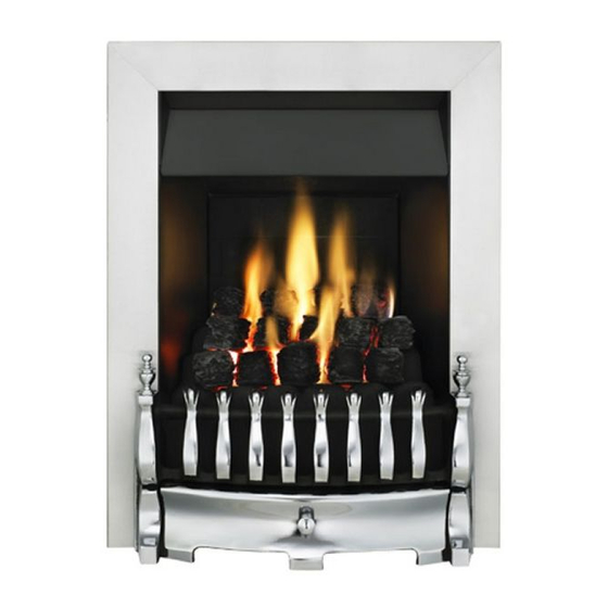
Model 956
INSET LIVE FUEL EFFECT GAS FIRE
Fitted with one of the following fascia.
Blenheim,Whitsbury
Seattle
Siva
or
fascia.
We trust that this guide gives
sufficient details to enable this
appliance to be installed, operated
and maintained satisfactorily.
However, if further information is
required, our
Valor Fires Technical Helpline will
be pleased to help.
Telephone 0844 879 35 88 (National
call rates apply in the United
Kingdom).
In the Republic of Ireland
Telephone 01 842 8222.
owner
INSTALLER: Please leave this guide with the
©
GDC Group Ltd. 2014
Advertisement
Chapters
Table of Contents

Related Manuals for Valor 956


Summary of Contents for Valor 956
- Page 1 However, if further information is required, our Valor Fires Technical Helpline will be pleased to help. Telephone 0844 879 35 88 (National call rates apply in the United Kingdom).
- Page 2 Warning: Any person who does any unauthorised act in relation to a copyright work may be liable to criminal prosecution and civil claims for damages. Valor Fires, GDC Group Ltd., Millbrook House, Hedge End, Southampton, SO30 2DF www.valor.co.uk Because our policy is one of constant development and improvement, details may vary slightly from those given in this publication.
- Page 3 BS EN ISO 9001 quality system accepted by the British Standards Institute. The Highest Standards Valor Fires is a member of SBGI and HHIC (Heating and Hot water Industry Council) that work to ensure high standards of safety, quality and performance. Careful Installation...
-
Page 4: Installer Guide
INSTALLER GUIDE INSTALLER GUIDE FOR OWNER GUIDE SEE PAGES 38 TO 51 © GDC Group Ltd 2014 Page 4... -
Page 5: Table Of Contents
INSTALLER GUIDE CONTENTS Section Heading Page INSTALLER GUIDE 4 - 37 OWNER GUIDE 38 - 51 1. IMAGES 2. SAFETY 3. APPLIANCE DATA AND EFFICIENCY 3.1 General information. 3.2 Efficiency. 4. GENERAL INSTALLATION REQUIREMENTS 4.1 Regulations, Standards and Law. 4.2 Ventilation requirements. 4.3 The Atmosphere sensing device (ASD). - Page 6 INSTALLER GUIDE CONTENTS (Continued) Section Heading Page 10. HOTBOX INSTALLATION 10.1 Method 1- Front fixing to fireplace surround. 10.2 Cable retention. 10.3 Floor sealing. 11. BURNER INSTALLATION 11.1 Burner and supply pipe installation. 11.2.Lighting the burner. 11.3 Operating the burner. 11.4 Inlet pressure check.
-
Page 7: Images
INSTALLER GUIDE 1. IMAGES Blenheim Whitsbury Siva Seattle © GDC Group Ltd 2014 Page 7... -
Page 8: Safety
INSTALLER GUIDE 2. SAFETY Installer Before continuing any further with the installation of this appliance please read the following guide to manual handling: The lifting weight of the appliance heat engine and hotbox is 4.4 kg. This does not include fascia or ceramics. One person should be sufficient to lift the fire. -
Page 9: Appliance Data And Efficiency
Model Efficiency % (Gross) Efficiency % (Net) 956 when converted to LPG The gross calorific value of the fuel has been used for this efficiency calculation. The test data from which it has been calculated has been certified by Advantica Certification services (0087). -
Page 10: General Installation Requirements
INSTALLER GUIDE The conversion of net efficiency to gross was achieved by multiplying the net efficiency by the following conversion factor from Table E3 of SAP 2005, rounding down to the nearest whole number. Conversion factor from net to gross efficiency Natural Gas 0.901 0.921... -
Page 11: Ventilation Requirements
INSTALLER GUIDE In the Republic of Ireland the installation must be carried out by a competent person and installed in accordance with: The current edition of IS 813 “Domestic gas installations”. All relevant national and local rules in force. The current building regulations Where no specific instructions are given, reference should be made to the relevant British Standard Code of Practice. -
Page 12: Chimney Preparation
INSTALLER GUIDE 4.6 Chimney preparation. 4.6.1 If the appliance is intended to be installed to a chimney that was previously used for solid fuel, the flue must be swept clean prior to installation. All flues should be inspected for soundness and freedom from blockages. 4.6.2 Any chimney damper or restrictor should be removed. -
Page 13: Fireplace Clearances
INSTALLER GUIDE 4.9 Fireplace clearances. 4.9.1 The minimum height from the base of the fireplace opening to the underside of any shelf made from wood or other combustible materials is detailed below. • For a shelf up to 150mm deep: Minimum height = 750mm. •... - Page 14 INSTALLER GUIDE Minimum mandatory Recommended Depth clearance to clearance to non- Height Width into Model combustible combustible (mm) (mm) room surfaces projecting surfaces for access (mm) beyond the front of purposes (mm). appliance (mm). Blenheim Seattle Siva Whitsbury Figure 3. Appliance dimensions and clearances (Fascia may differ from that shown) (The appliance dimensions ‘A’, ‘B’...
-
Page 15: Installation Options
INSTALLER GUIDE 4.10 Installation options. In the United Kingdom, as supplied, the appliance can be installed in the following situations: - 4.10.1 Conventional fireplace and hearth. To a fireplace complete with hearth as shown in figure 4. Chair brick removal may not be required providing at least 50mm clearance is available from the flue outlet to any fireplace component. -
Page 16: Metal Flue Box And Hearth
INSTALLER GUIDE 4.10.2 Metal flue box and hearth. The appliance can be installed to a fireplace incorporating a metal flue box complying with the constructional requirements of the current edition of BS 715 and with a flue conforming to BS EN 1856 part 1. The dimensions of the flue box must conform to those shown in figure 5. -
Page 17: Flues
INSTALLER GUIDE current edition. The flue blocks must have a minimum (Depth from the front of the fireplace opening) width not less than 63mm and a cross-sectional area not less than 13,000mm 2 . Older editions of BS1289 required a cross-sectional area of 13,000mm 2 . The current revision of the standard requires 16,500mm 2 . -
Page 18: Propane Gas Fires
INSTALLER GUIDE 4.12 Propane gas fires. Propane gas appliances must not be installed in a room, which is built entirely below ground level (See BS 5871 Pt2). 5. PACK CONTENTS Items below with a letter reference are supplied on a film wrapped card. Remove all the items carefully to prevent damage. - Page 19 INSTALLER GUIDE Figure 7. Pack contents (Not all of the components listed may be required) © GDC Group Ltd 2014 Page 19...
- Page 20 INSTALLER GUIDE Figure 7. Pack contents continued. © GDC Group Ltd 2014 Page 20...
-
Page 21: Fireplace Check
INSTALLER GUIDE 6. FIREPLACE CHECK 6.1 Soundness for appliance attachment. Two primary methods of retaining the appliance are provided: - By fixing to the fireplace front surround. Using concealed tension cables fixed to the rear of the fireplace opening. The methods are detailed in section 10 of this manual. Before selecting the retention method, consult with the customer. -
Page 22: Ignition Check
INSTALLER GUIDE 7. IGNITION CHECK Before attempting to install, it is worth checking that the ignition system performs satisfactorily. Set the control knob to the ‘OFF’ position. Depress the control knob and rotate it anticlockwise to the ‘pilot ignition’ position. A 'click' will be heard as the integral piezo operates. -
Page 23: Preparing Appliance For Installation
INSTALLER GUIDE 9. PREPARING APPLIANCE FOR INSTALLATION 9.1 Appliance preparation. 1. Remove any transit tape and packing and inspect for any evidence of mishandling which might affect the performance of the fire. Each unit is flame tested before it leaves the factory and as a result there may be slight discolouration around the burner ports. -
Page 24: Hotbox Installation
INSTALLER GUIDE Fit the restrictor as shown in figure 12 using the two ‘B’ screws provided. Figure 12. Fixing restrictor 10. HOTBOX INSTALLATION 10.1 Method 1- Front fixing to fireplace surround. 1. Make sure that the fireplace front surround area is sound enough to take the wall plugs and screws. -
Page 25: Cable Retention
INSTALLER GUIDE 10.2 Cable retention. 1. Make sure that the relevant areas at the fireplace back are sound enough to take the screw eyes. If these areas have deteriorated due to prolonged use they should be made sound with a suitable cement. 2. -
Page 26: Floor Sealing
INSTALLER GUIDE 9. Pull each cable taut. Push the cable adjusters hard up against the back panel. Tighten the screws in the adjusters so that they clamp the cables in position. Apply tension to the cables by turning the hexagonal adjusters by hand (See figure 17). -
Page 27: Burner Installation
INSTALLER GUIDE 11. BURNER INSTALLATION 11.1 Burner and supply pipe installation. 1. Refit the burner unit to the hotbox using the two screws removed previously. The burner securing points should be on the inside of the hotbox as shown in figure 19. 2. -
Page 28: Inlet Pressure Check
INSTALLER GUIDE 11.4 Inlet pressure check. The appliance is pre-set to give the correct heat input at the inlet pressure shown in section 3 of this manual. No adjustment is necessary. 1. Check the inlet pressure by fitting a pressure gauge at the test point. -
Page 29: Operating The Burner
INSTALLER GUIDE flame appears at the pilot. There may be a delay before the pilot lights due to air being purged from the system. When a flame appears at the pilot keep the control knob depressed and hold the pilot ignition position for five seconds. When the control knob is released the pilot flame should remain lit. -
Page 30: Fascia And Firefront Installation
Figure 22. Firefront minimum open area requirements (The firefront may differ from that shown) - For models supplied with a Valor Fires firefront, the open area may differ slightly from that stated in figure 22. In these cases the firefront will have been tested with the fire and found to be satisfactory for use with the fire. - Page 31 INSTALLER GUIDE 13.3 Fitting the Blenheim firefront. 1. Place the firefront / casting on top of the hearth centrally between the fascia. 2. On models with a two piece firefront place the lower front cover casting / ash pan below the front casting. 13.4 Fitting the Seattle/Siva firefront.
-
Page 32: Spillage And Flame Supervision Checks
INSTALLER GUIDE 14. SPILLAGE AND FLAME SUPERVISION CHECKS 14.1 Check for spillage. A spillage check must be made before leaving the installed appliance with the customer. Make this with all the ceramic fuel effect pieces and firefront casting / firefront in position. 1. -
Page 33: Final Review
This monitoring system must not be adjusted, bypassed or put out of operation. This monitoring system, or any of its parts, must only be exchanged using Valor Fires authorised parts. 15. FINAL REVIEW 1. COMPLETE THE INFORMATION IN THE WARRANTY AND SERVICE SECTION OF THE OWNER GUIDE (See last pages of the OWNER guide). -
Page 34: Servicing And Parts Replacement
INSTALLER GUIDE 10. Advise the customer that the firefront, fascia, hotbox and ceramic pieces can be cleaned as described in the owner guide and that the loose ceramic fuel effect pieces must be replace as described in the installer and owner guide supplied with them. Stress that no extra ceramic fuel effect pieces must be added over and above those supplied with the appliance and that any replacements must only be the authorised spares. -
Page 35: Checking The Aeration Setting Of The Burner
INSTALLER GUIDE After servicing, make sure that the ceramic wall is replaced as described in this guide and the ceramic fuel effect pieces are replaced correctly as described in the installer and owner guide supplied with the ceramic fuel effect. The ceramic fuel effect guide may have been placed inside or attached to this guide. -
Page 36: To Remove The Pilot Unit
INSTALLER GUIDE 3. Detach the pilot pipe from the pilot unit. 4. Detach the thermocouple from the gas valve 5. Detach the electrode lead from the rear of the piezo spark generator on the gas valve. 6. Remove the two screws securing the pilot unit (See figure 30). -
Page 37: To Remove The Burner
INSTALLER GUIDE 16.6 To remove the main burner injector. (See figure 33). 1. Remove the burner (See section 16.5). 2. Remove the burner clamping screw (See figure 33). 3. Unscrew the injector from the burner. 4. Refit in the reverse order. 16.7 To remove the appliance from the fireplace. -
Page 38: Owner Guide
OWNER GUIDE OWNER GUIDE FOR WARRANTY AND SERVICE INFORMATION SEE PAGES 48 TO 51 © GDC Group Ltd 2014 Page 38... - Page 39 OWNER GUIDE LIST OF CONTENTS Section Page SAFETY APPLIANCE DIMENSIONS AND CLEARANCES GAS CONSUMPTION OPERATING YOUR FIRE The Oxysafe flame sensing and flue blockage safety system. Lighting the pilot. Lighting the burner. Selecting the heat setting. Turning the fire back to pilot setting. Turning the appliance off.
-
Page 40: Safety
OWNER GUIDE SAFETY IF YOU SMELL GAS DON’T SMOKE. EXTINGUISH ALL NAKED FLAMES. DON’T TURN ELECTRICAL SWITCHES ON OR OFF. TURN OFF THE GAS SUPPLY AT THE METER OR TANK AS APPROPRIATE. OPEN DOORS AND WINDOWS TO GET RID OF THE GAS. IMMEDIATELY CALL THE GAS EMERGENCY SERVICE FROM A NEIGHBOURS PHONE - SEE YOUR LOCAL TELEPHONE DIRECTORY. - Page 41 OWNER GUIDE Do always use a fireguard complying with BS 8423 for the protection of young children, pet animals, the elderly or infirm. Do wait three minutes before attempting to relight if the fire is switched off or the flames are extinguished for any reason.(Your fire is fitted with a safety device that will automatically shut off the gas supply to the fire, if for any reason, the flame goes out).
-
Page 42: Appliance Dimensions And Clearances
OWNER GUIDE APPLIANCE DIMENSIONS AND CLEARANCES Minimum mandatory Recommended Depth clearance to clearance to non- Height Width into Model combustible combustible (mm) (mm) room surfaces projecting surfaces for access (mm) beyond the front of purposes (mm). appliance (mm). Blenheim 587.5 Seattle 587.5 Siva... -
Page 43: Gas Consumption
Has a minimum natural gas input of 2.07kW (Net) Has a minimum natural gas output of 1.15kW Model 956 when converted using kit number 0595221 Has a maximum propane gas input of 6.1kW (Gross) Has a maximum propane gas output of 3.1kW Has a minimum propane gas input of 3.8kW (Gross) -
Page 44: Operating Your Fire
OWNER GUIDE OPERATING YOUR FIRE PLEASE NOTE When operating your fire for the first time, some vapours may be given off which may cause a slight odour and could possibly set off any smoke alarms in the immediate vicinity. These vapours are quite normal with new appliances. They are totally harmless and will disappear after a few hours use. -
Page 45: Lighting The Burner
OWNER GUIDE Lighting the burner. Once the pilot light is established, the main burner can be lit by depressing and turning the control knob anticlockwise to the ‘HIGH’ position. Selecting the heat setting. In order to change from one setting to another depress the control knob slightly and turn the knob to the required position. -
Page 46: Cleaning Your Fire
OWNER GUIDE CLEANING YOUR FIRE To maintain the high performance and quality finish of your Valor Fires appliance, please follow these guidelines: Before attempting to clean the fire, please remember to turn off the fire and wait for the appliance to cool completely. The fire will retain heat for some time before cleaning can begin. -
Page 47: Ceramic Fuel Effect Fitting
OWNER GUIDE CERAMIC FUEL EFFECT FITTING The installer and owner guide for the ceramic fuel effect is separate from this guide. The installer may have attached it to this guide or placed it inside. It is important that the installer and owner guide for the ceramic fuel effect is followed correctly. If replacing the ceramic fuel effect, where a new guide is supplied, follow the installer and owner guide supplied with the replacement fuel effect. -
Page 48: Warranty And Service
OWNER GUIDE WARRANTY AND SERVICE Standard Warranty Terms & Conditions The warranty is for 12 months subject to contract. In the United Kingdom servicing can be carried out either by a GDC service engineer or a GAS SAFE REGISTER engineer. Outside of the United Kingdom servicing can be carried out either by a CORGI or GAS SAFE REGISTER engineer. - Page 49 OWNER GUIDE When calling the GDC Helpline, it would be helpful if you could have the following information to hand:- Fire serial number and fascia code (Located on the information label - See figure 5 on page 50)*. Date of installation*. Your installer name and address details*.
- Page 50 OWNER GUIDE The following pages are to be completed by the installer: Installer Details (Block Capitals) Installer Name Gas Safe Register or Corgi Registration Number. Company Name. Company Address Company Telephone number Company Fax number Figure 5. © GDC Group Ltd 2014 Page 50...
- Page 51 Fascia code - Can be found on information label (Block Capitals) A LABEL CONTAINING THE FASCIA CODE FASCIA LABEL MAY HAVE BEEN TO BE AFFIXED HERE PLACED INSIDE THIS BOX. Brand (Please tick) Valor Other......Date of Installation © GDC Group Ltd 2014 Page 51...
- Page 52 © GDC Group Ltd 2014...
Need help?
Do you have a question about the 956 and is the answer not in the manual?
Questions and answers